From Graphs to Euclidean Virtual Worlds: Visualization of 3D Electronic Institutions Sara Drago1
Anton Bogdanovych2 Helmut Berger3 1
2
Simeon Simoff2
Department of Computer Science, University of Genoa, via Dodecaneso 35, 16146 Genova, Italy {drago,ancona}@disi.unige.it
Faculty of Information Technology, University of Technology Sydney, Sydney, NSW, Australia {anton,simeon}@it.uts.edu.au 3
4
Electronic Commerce Competence Center - EC3 Donau-City-Strasse 1, A-1220 Wien, Austria
[email protected]
Artificial Intelligence Research Institute (IIIA-CSIC) Barcelona, Catalonia, Spain
[email protected]
Abstract In this paper we propose an algorithm for automatic transformation of a graph into a 3D Virtual World and its Euclidean map, using the rectangular dualization technique. The nodes of the initial graph are transformed into rooms, the connecting arcs between nodes determine which rooms have to be placed next to each other and define the positions of the doors connecting those rooms. The proposed algorithm is general enough to be used for automatic generation of 3D Virtual Worlds representation of any planar graph, however, our research is particulary focused on the automatic generation of 3D Electronic Institutions from the Performative Structure graph. Keywords: 3D Electronic Institutions, Rectangular Dualization, Virtual Worlds. 1
Massimo Ancona1 Carles Sierra4
Introduction
Nowadays, our society becomes extremely experience focused. The software developers and designers take significant care to providing good user experience in their products. In other industries like entertainment, business, travel and even health care experiences are bought and sold together with products and services or even separately from them. One of the paradoxes of this new economical phenomenon is that those experiences sometimes become much more valuable (expensive) than the products or services they adhere to (Pine & Gilmore 1998). The advent of communication networks and increasing computational power of the hardware created new possibilities of enhancing the user experience in software products, helping to adapt to the new economical circumstances. One of the quite recent technologies, 3D Virtual Worlds, provides the exciting possibility to create systems that look similar to our everyday life visual surroundings. Due to c Copyright 2007, Australian Computer Society, Inc. This paper appeared at the Thirtieth Australasian Computer Science Conference (ACSC2007), Ballarat, Australia. Conferences in Research and Practice in Information Technology (CRPIT), Vol. 62. Gillian Dobbie, Ed. Reproduction for academic, notfor profit purposes permitted provided this text is included.
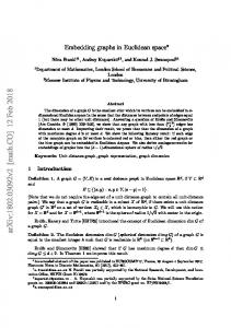
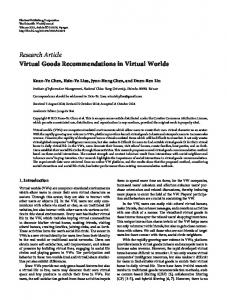
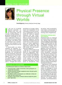
this similarity, such systems literally help to immerse users into software products. With 3D modelling we can imitate real objects and profit from users’ familiarity with their affordances1 . The use of avatars2 implicitly incorporates location awareness and offers mechanisms for social interaction, supporting to a certain extent the way humans operate and interact in the real world. In this way social interaction between participants in an immersive environments becomes an important integral feature of software solutions. 3D Electronic Institutions are a step towards such new methods of software design for the open systems that are based on the metaphor of 3D Virtual Worlds. The unique characteristic of open systems is that their components are unknown beforehand, can change over time and can be both human and software agents developed by different parties (Hewitt 1986). Examples of such open systems include computer games, virtual travel agents, E-Commerce solutions etc. The 3D Electronic Institutions provide ways to control the security aspects of those systems and offer mechanisms of their automatic visualization in 3D Virtual Worlds. Figure 1 presents the methodology for achieving this visualization. On the first phase the real world open system is selected to be implemented as an institution. It should clearly exhibit the need for institutional presence: allow interactions with complex protocols and express a need for strong security control. From the above mentioned examples we see virtual travel agents (Bogdanovych, Berger, Simoff & Sierra 2006) and various E-Commerce solutions (Bogdanovych, Berger, Sierra & Simoff 2004) as potential applications. Next, the institution is formalized and mapped onto a 3-dimensional space. In order to formalize an institution we utilize the Electronic Institutions methodology (Esteva 2003), which helps to structure the interactions between different components (participants) by imposing, and enforcing, well established conventions based on organizational principles. The enforcement of organizational conventions is achieved by separating patterns 1 A property of an object, or a feature of the immediate environment, that indicates how to interface with that object or feature. The empty space within an open doorway, for instance, affords movement across that threshold. A couch affords the possibility of sitting down on it. 2 3D character representing a participant in a Virtual World
Figure 1: The Methodology for Visualization of 3D Electronic Institutions
of conversational activities into several methodological entities (scenes), assigning different roles to different types of participants, specifying the rules (protocols) for inter-participant interactions and defining the role flow of participants between scenes. The specification of scenes and the role flow are done in a form of a directed planar graph, where nodes represent scenes and arcs and their labels define the role flow. This graph, which is called Performative Structure (Esteva 2003), forms a basis for the visualization of the system in 3D Virtual Worlds (as shown on Figure 1). The nodes are visualized as rooms and arcs are transformed into doors connecting the rooms. To make the visualization of 3D Electronic Institutions more efficient we propose to transform the Performative Structure graph (an important part of the 3D Electronic Institution Specification) into a 3D Virtual World in a fully automatic way. To our knowledge there are no algorithms being proposed for performing such a transformation. However, there is a technology called rectangular dualization (He 1997). It is used for the transformation of a planar graph into a partition of a rectangle R of the plane into subrectangles, where edges of the original graph determine the adjacency of the generated rectangles. Moreover, rectangular dualization offers a space optimal solution for such transformations. However, not all planar graphs admit a rectangular dual, a fact that precludes most applications of the method. In order to overcome this drawback, we developed an algorithm which transforms each planar graph into a new graph by inserting into it a minimum number of new vertices and edges for forcing it to admit a rectangular dual. In the particular case of 3D Electronic Institutions the classical rectangular dualization algorithm is used to create a map of the institution, which is further transformed into a 3D Virtual World. The map is very close to the rectangular dual of the graph representing the adjacencies defined between each pair of rooms belonging to the same floor of the building. In this sense the rectangular dual exploits location awareness defined by the frequency of interactions forecasted for the inhabitants of the same floor and can be used for minimizing the distance between two agents that are supposed to have frequent interactions during their everyday activity. As the Performative Structure graph is not necessarily planar, the original algorithm is changed to firstly remove the intersecting arcs of the source graph forcing it being planar. We also extended the algorithm in such a way that the vertex peers related to removed arcs are stored, and after the generation of the 3D virtual environment the interconnected teleports are placed in the corresponding rooms. The 3D Electronic Institutions, on the one hand, introduce structured interactions into the chaotic nature of Virtual Worlds. On the other hand, the model we propose allows semiautomatic generation of 3D Virtual Worlds from Electronic Institutions specification and runtime maintenance of those worlds. This
will increase the speed of Virtual Worlds development in the future and make online communities more secure. Another technical benefit of this approach is that 3D Virtual Worlds provide general and very intuitive way for human navigation and interaction within. This means that once the 3D Electronic Institution is generated - there is no need for any additional software code to be written to enable humans to start interacting. Furthermore, 3D Electronic Institutions offer a first formal methodology for the design of 3D Virtual Worlds. The remainder of the paper is structured as follows. Section 2 describes the 3D Electronic Institutions concept. Design considerations for 3D Virtual Worlds are presented in Section 3. The motivation for visualizing 3D Electronic Institutions in an Euclidean way are given in Section 4. In Section 5 the generic description of the rectangular dualization method is given. Section 6 explains how the rectangular dualization can be adapted to the generation of 3D Electronic Institutions. Concluding remarks and details of future work are presented in Section 7. 2
3D Electronic Institutions
3D Electronic Institutions is a concept that appeared from the combination of the Electronic Institutions and 3D Virtual Worlds technologies. This combination resulted in a working methodology, supported by a number of tools, for designing highly secure and reliable immersive 3D solutions. Applying 3D Electronic Institutions methodology requires 4 important steps to be accomplished: 1. Specification of an Electronic Institution using ISLANDER (Esteva, de la Cruz & Sierra 2002). 2. Annotation of the Electronic Institution specification with components of the 3D Virtual World. 3. Automatic generation of the corresponding 3D environment. 4. Integrating the 3D Virtual World into the institutional infrastructure. On the specification stage the institutional regulations are defined. An institution is seen as an infrastructure for regulating the interactions of autonomous agents, which can be either humans or autonomous software modules (further referred as autonomous agents). The notion of institutions introduces a dramatic difference to the development of multiagent systems compared to the majority of present solutions. Instead of focusing on the implementation details of each particular agent, a system-oriented view is taken. We assume that participating agents may be heterogeneous and self-interested, and we cannot rely on their correct behavior. Therefore, the institution is designed as a set of limitations which every participant have to comply with. This assumption permits
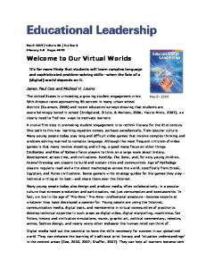
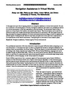
Figure 2: An example of a simple institution.
that agents behave autonomously and make their decisions freely up to the limits imposed by the institution. The rules about user behavior in an institution are introduced on the specification phase determined by three types of conventions: • Conventions on language, the Dialogical Framework. Determines what language ontology and illocutionary particles agents should use. It also fixes the organizational structure of the society of agents, that is, which roles agents can play, and what the incompatibilities and relationships among the roles are. • Conventions on activities, the Performative Structure. This dimension determines in which types of dialogues agents can engage. Each different activity an agent may perform is associated to a dialogue among the group of agents involved in that activity. These (structured) dialogues are called scenes. The Performative Structure fixes which protocol (possible dialogues) can be enacted in each scene, which sub-language of the overall institutional language can be used in each scene, and which conventions regulate the in and out flux of agents in scenes. Finally, the minimum and maximum number of participants is limited by the specification of scenes. Scenes are interconnected to form a network in order to represent sequence of activities, concurrency of activities or dependencies among them. Agents leave scenes where they have been playing a given role and enter other scenes to play the same or a different role. This transit of agents is regulated by special (simple) scenes called transitions. Transitions re-route agents and are where synchronization with other agents (if needed) takes place. Sometimes new scenes can only be enacted by a group of agents, or agent can only join scenes as members of a group. Transitions are the places where agents synchronize before moving on. • Conventions on behavior, the Norms. Institutions impose restrictions on the agents actions within scenes. These actions are basically restricted to: illocutions and scene movements. Norms determine the commitments that agents acquire while talking within an institution. These commitments restrict future activities of the agent. They may limit the possible scenes to which agents can go, and the illocutions that can henceforth be uttered. While the specification strictly defines the limitations, it also helps to understand what participants
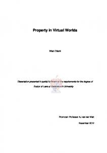
need in order to operate in the institution. Some elements of the specification have conceptual similarities with building blocks in 3D Virtual Worlds, which makes it possible to automatically generate a 3D representation of the specification. The scenes and transitions, for example, are transformed into 3D rooms, connections correspond to doors, and the number of participants allowed in a scene determines the size of a room (see (Bogdanovych, Berger, Sierra & Simoff 2005) for details). To make the resulting 3D Virtual World more appealing, the specification is annotated with additional 3D related components (objects, textures, animations etc). After accomplishing this step the generated 3D Virtual World is ready to be visualized and the 3D Electronic Institution infrastructure will be executed to take care of the validity of interactions between participants, verify the permissions of participants to access different scenes and will make sure that all the institutional norms and obligations are imposed. 3D Electronic Institutions have 2 different levels of execution: institutional level and social level. The institutional level makes sure that the institutional rules are not violated. On this level a participant is restricted to sending a text message to the institution for verification, requesting to perform an action. If under the current circumstances the action is allowed to be performed without violating the rules, the agent receives back a response and the action is visualized. The way the actions are visualized can not be changed, as well as their execution can not be terminated. For human participants sending text messages is transparent as it happens as a result of their actions in the Virtual World. Actions that are not controlled by the institution are performed at the social level. These actions are executed directly by the participant without prior verification by the institution. For example, there is no need for the institution to specify how the participants should walk from one room to another. Figure 2 presents an example of a simple institution and shows the actions performed on both social and institutional level. The institutional level actions include: (enterScene, exitScene, enterTransition, exitTransition and login). On the social level these are: moving, clicking, colliding, rotating etc. The black arrows on the picture show the trajectory of the participant’s movement through registrationRoom, meetingRoom to TradeRoom. The black figure represents the participant, other figures correspond to internal agents (employees of the institution) Receptionist and Auctioneer. The Receptionist welcomes the participant in the RegistrationRoom, verifies the login and password and unlocks the doors to other scenes if the
identity of the participant is proven. The Auctioneer sales different goods in the TradeRoom. It announces the current product to be auctioned, waits for incoming bids and sells it to the winner of the auction. The MeetingRoom is used for social interaction between buyers. 3
Design Considerations Worlds
for
3D
Virtual
Human beings live in a well structured space following different metaphors. Popular everyday metaphors, such as buildings, streets, landscapes etc. are widely used in Virtual Worlds (Russo Dos Santos, Gros, Abel, Loisel, Trichaud & Paris 2000). We adopt this class of metaphors for the visualization of 3D Electronic Institutions. A visual representation of 3D Electronic Institutions is mapped onto the metaphor of a small town. Each building constitutes a separate institution, public transport might be used to access different institutions, rooms relate to different activities that can be performed in the institution. Virtual Worlds are spaces were people “meet”. Social interaction is a key feature and Virtual Worlds have to provide support for communication and collaboration of their participants (Smith, Maher & Gero 2003). Furthermore, not all the inhabitants of Virtual Worlds are under human control. Some of the participants are autonomous agents that have an embodied representation. Thus, a Virtual World, which is populated by automated embodied agents and agents driven by human beings, has to take care of their different abilities. During the construction of a 3D representation of a virtual environment it is important to keep the benefits of traditional 2D interface design in mind (Bowman, Kruijff, LaViola & Poupyrev 2001). Participating in a 3D environment in which users can manipulate 3D objects, doesn’t necessarily mean exclusion of 2D user interface elements. In fact, the interaction with 2D interface elements offers a number of advantages over a 3D representation for some tasks. Most efficient selection techniques, for instance, are widely realized in 2D, whereas, the selection process in a 3D user interface must consider the user’s viewpoint and distance to the object. Combining the advantages of 2D and 3D design is a very powerful and intuitive approach for the construction of Virtual Worlds. Besides the benefits obtained by adding an additional dimension for visualization purposes, this new degree of freedom introduces new difficulties (Nielsen 1998). More precisely, not every application domain has a suitable and usable representation in a three-dimensional way. The more abstract (the more non-physical) an application domain becomes, the harder it gets to visualize it in 3D. Consider for example, a 3D representation of a hyperspace like the World Wide Web. Navigating through a threedimensional representation of web sites will end up in a rather confusing task for most users. Thus, it is of great importance to consider carefully whether to use the “third dimension” for the particular application. In our approach we take advantages from both ways of representation. The visualization of 3D Electronic Institutions contains 3D elements (3D Virtual World itself) and 2D Elements (map of the institution and the backpack which helps to remind user’s obligations towards the institution). 4
Euclidian Representation
Navigation is an important issue in the design of 3D virtual environments. Navigational problems may
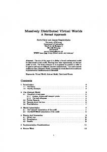
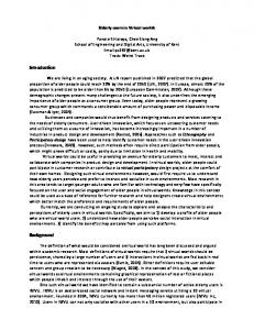
Figure 3: Euclidian representation. Human knows that Room 1 must be behind Door 4.
break the immersive experience and lead to the rejection of the system by end users. Humans live in an Euclidian world: distances and angles help humans to navigate it. In our opinion, the better our system imitates real world, the more it supports social factors like communication and collaboration. 3D Virtual Worlds could certainly be programmed without an Euclidian model in mind. For instance, we could create a series of rooms interconnected by teleportation3 . In this case the distance between each two connected rooms will be equal to zero. Technically, such a solution poses much less problems for development, as there is no need to control the positioning of every room. The simplest implementation solution here would be to have each room stored as a separate file, which is loaded on demand when user wants to teleport into the corresponding room. Despite the technological simplicity of the nonEuclidean way of representing an institution as a Virtual World, such an approach may cause navigational problems for the participants inside. Moreover, we believe that having an Euclidian representation of the Electronic Institution helps in learning of the institutional structure. To demonstrate the confusion a participant may experience navigating a non-Euclidean Virtual World consider the situation (Figure 3) where the user walks from Room 1 to Room 4 following the arrows. In Room 4 the human should correctly expect that Room 1 is behind Door 4, otherwise the believability of the interface will be lost. This expectation of Room 1 is based on both the consistency of the navigational layout and intuitive feeling about the size of visited rooms. Unfortunately, the problems of Euclidean and nonEuclidean visualizations of Virtual Worlds are understudied. Despite this fact, there is some research evidence in favor of our initial hypothesis that motion techniques which instantly teleport users to new locations are correlated with increased user disorientation. In (Bowman, Koller & Hodges 1997) the authors present the results of their user study, where one of the questions was whether teleportation can cause navigational problems. The study clearly shows that teleportation (or jumping technics, as it is called in 3 the process of moving users from one place to another more or less instantaneously, without passing through the intervening space
the paper) can reduce the user’s spatial awareness. With teleportation there is no sensation of motion, only that the world has somehow changed around the user. It is a technique whose motion has no analog in the physical world. Moreover, authors came to a conclusion that frequent teleportation may even reduce the sense of presence in a Virtual World, which would eliminate one of the most important benefits of the 3D technology. Another research (Ruddle 2000) provides some support in favor of the assumption behind the example presented on Figure 3. This user study analyzed the navigational efficiency of participants in the overlapping Virtual Worlds. The results suggest that some users had great difficulties navigating them. Even the experimenter, who informally observed participants as they travelled through the Virtual Worlds, was often unsure of which door to go through to enter a particular room. In order to avoid the difficulties with navigation and spacial awareness of participants we propose an automatic technique for generation of an Euclidean representation of a 3D Electronic Institution. In our case this Euclidian representation is generated from the graph representing the performative structure. To achieve this, we propose to adapt rectangular dualization technology. The algorithm presented in Section 5 removes the intersecting arcs of the source graph to force it being planar. We extend the algorithm in such a way that the vertex peers related to removed arcs are stored, and after the generation of the 3D virtual environment the interconnected teleports are placed in the rooms represented by those vertices. Although the teleports will still be present, the number of them is supposed to be insignificant to pose any navigational problems. 5
Rectangular Dualization
Rectangular dualization was originally used to generate rectangular topologies for floor planning of integrated circuits: by a floor plan, we partition a rectangular chip area into rectilinear polygons corresponding to the relative location of functional entities of the circuit (He 1997). In spite of the specialized problems that motivated its origin, rectangular dualization contributes to the resolution of many other visualization problems having in common with circuits the condition that objects and their interoccurring relations are represented by means of a planar graph. An example is given by network configuration issues, when human interventions of design or topology adjustment are needed and a physical or logical layout representation becomes essential for the human operator. In fact, a very serious problem to cope with in graph drawing is how to represent edges in such a way that they do not appear too close together. The aim is to enhance the readability of the drawing, making easier to find out which nodes are connected by an edge. The very first solution to this problem is to avoid edge crossings, and this motivates the interest for planar graphs, that are precisely those graphs that can be drawn in the plane with no edge crossings. The choice for planar graphs is not only a representation facility but is primarily validated by real-world examples where the presence of crossing links may produce technical drawbacks. Further on, since a major optical effort is encountered in the proximity of vertices, where adjacent edges need to meet in a point, several studies have been spent in devising drawing algorithms capable of maximizing angular resolution, i.e. the smallest angle between adjacent edges, in such a way that lines representing connections are kept as separate as possible;
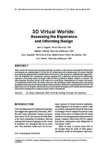
Figure 4: A planar triangulated graph and two possible rectangular layouts.
rectangular dualization results to be an effective visualization method since only orthogonal lines occur. Thomassen proved that every planar graph is the intersection graph of a collection of three-dimensional boxes, with intersections occurring only in the boundaries of the boxes. Furthermore, he characterized the graphs that have such representations (called strict representations) in the plane. These are precisely the proper subgraphs of 4-connected planar triangulations. Together with earlier work (Thomassen 1984), his work yields an algorithm for testing a graph G to see if it admits a rectangular dual and, if so, constructing such a representation. His proof does not look to lead to an efficient algorithm, however: for a graph having n nodes, a straightforward implementation of his method requires at least O(n3 ) time. Bhasker and Sahni (Bhasker & Sahni 1988) developed linear-time algorithms to find a rectangular dual for graphs satisfying Kozminski and Kinnen criterion. In (Kant & He 1993) Kant and He explain how to construct a rectangular dual from a regular edge labeling (REL, for short) and present two algorithms to compute such labeling, one based on an edge contraction technique and the other on a canonical ordering. A later work of Saidur presents a linear time algorithm which finds a rectangular grid drawing using a depth first search (Md. Saidur 1999). In (Buchsbaum, Gansner, Procopiuc & Venkatasubramanian n.d.) is shown how the works above may be combined to produce an efficient algorithm for constructing rectangular duals with asymptotically bounded area. Lai and Leinwand (Lai & Leinwand 1988) first presented the idea of forcing rectangular dual admissability by introducing crossover vertices breaking all separating triangles. They conjectured that finding a minimal set of crossover vertices was a N P -complete problem and performed non optimal introduction of crossover vertices in linear time. Ancona et al. (Accornero, Ancona & Varini 2000) showed that all separating triangles can be optimally broken in polynomial time and presented an asymptotical bound of O(n3 ), which some discussion can refine up to O(mn lg n), being m the number of edges and n the number of nodes of the input graph. In the following section we describe an implementation that transforms graphs that do not admit rectangular duals into graphs admitting one by adding the minimum number of new vertices. 5.1
Definitions
A rectangular dual of a planar graph G = (V, E) is a rectangle R with a partition of R into a set Γ = {R1 , ..., Rn } of non overlapping rectangles such that: • no four rectangles meet at the same point; • there is a one-to-one correspondence f : V −→ Γ such that two vertices u and v are adjacent in G
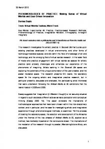
Figure 5: Generating the 3D representation of a Performative Structure graph.
if and only if their corresponding rectangles f (u) and f (v) share a common boundary. It is easy to see that if a graph admits a rectangular dual, it may not be unique (see Figure 4). On the other hand, some graphs do not admit rectangular dual. Kozminski and Kinnen present necessary and sufficient conditions under which a plane graph G has a rectangular dual (Kozminski & Kinnen 1984): the most important point is the absence of separating triangles (i.e. 3-vertex cycles with at least one vertex in their interior), a condition that in planar triangulations is equivalent to 4-connectivity whose meaning is that the removal of any set of 3 vertices leaves the remainder of G connected. A matching in G is a subset M of edges such that for every vertex v, at most one edge e covers v, that is v is an endvertex of e. A graph is k-regular if every vertex has degree k, that is k incident edges. A maximum matching is a matching with largest possible cardinality. If the graph is weighted, we may even consider a maximum weight matching. A bridge is an edge whose removal disconnects G. Whenever we speak of a planar graph, we assume that some planar embedding has been fixed, which corresponds to the idea of depicting an existent physical connection among real objects (in this perspective, it would be more accurate to speak of plane graphs, i.e. planar graphs with a fixed embedding in the plane). A structured
graph is a form of abstraction applied to a large graph in order to make it modular and more manageable. The abstraction consists in collapsing a subgraph to a single vertex (called a macrovertex ), or to a single link (called a macrolink ) thus obtaining a simpler and hierarchically described graph. The structuring operation is usually iterated recursively until a large graph is decomposed into relatively small and manageable components and sub-components defined at several levels of nesting, adopting a methodology that is usually applied to every large project (software and hardware design) involving hundreds or thousands of components. 6
Implementation Details
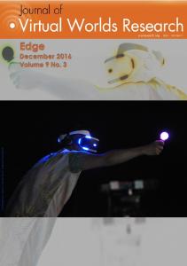
To visualize the 3D Electronic Institutions we use the metaphor of architecture. Each institution is visualized as a building, and each building consists of different rooms. This approach helps to provide users with the interface close to the users’ everyday life surroundings. From the Performative Structure graph, a highly important part of the specification, both the 3D representation of the institution and the map of the institution are created. The process of automatic generation of a 3D Virtual World and a map from this graph is depicted in Figure 5.
Figure 6: A planar embedding of a graph with its input file.
In the upper left corner in Figure 5 the source Performative Structure graph is presented. This graph corresponds to the simple institution from Figure 2. Rectangular shapes represent scenes, triangular shapes are transitions, arcs connecting the nodes are connections. As it was already mentioned earlier, the scenes and transitions are transformed into rooms, and the connections are visualized as doors. In this example the 3D Electronic Institution consists of 3 functional rooms: registration room, meeting room and trading room. These 3 rooms are contained inside a building and the building itself is placed into a garden. Root and Exit scenes are not functional, they only determine entrance and exit points of the institution, so from the 3D Virtual Worlds prospective entering these rooms will force exiting the institution building and moving into the garden. The automatic generation is done in 4 steps. On Step 1 the redundant information contained in the Performative Structure is filtered out. If some nodes of the graph, for example, are connected with more than one arc only one randomly selected arc is left and all the others are deleted. Next, the performative structure graph is transformed into a form accessible by the OCoRD software. The OCoRD (Optimal Constructor of a Rectangular Dual) software is a tool aiming at the solution of floorplanning problems and at the orthogonal drawing of planar networks. Given a planar embedding of the graph, it accepts a numeric adjacency lists and, if the graph admits a rectangular dual, it returns its coordinates in the plane and a drawing in fig format. On Step 2 OCoRD transforms a graph not admitting a rectangular dual into a 4-connected supergraph satisfying Kozminski and Kinnen criterion and creates its rectangular dual. In order to force an input graph to satisfy the Kozminski and Kinnen criterion it is neccesary to eliminate separating triangles by adding crossover vertices on an edge of each separating triangle (Lai & Leinwand 1988). The breaking method implemented in OCoRD is optimal, in other words it only adds a minimum number of such crossover vertices and inserts them in strategical positions, such that a single vertex may break two triangles or more (Accornero et al. 2000). OCoRD performs this transformation in the following steps: 1. four external vertices are added according to the construction presented in (Kant & He 1993);
2. the geometrical dual of the graph is computed and faces belonging to a separating triangle are detected and clustered together in a single macrovertex; 3. a covering affecting macrovertices is computed; the effect is that all separating triangles are optimally broken by inserting new vertices in some strategical places along some of their constituting edges; 4. the resulting graph is triangulated with the algorithm described in (Biedl, Kant & Kaufmann 1997). The result of this transformation is a graph satisfying triangularity and four-connectivity. Faces belonging to a separating triangle are detected in linear time (Chiba & Nishizeki 1985). Separating triangles are broken by solving a minimum unweighted macrocovering problem on the geometrical dual of input graph. The macro-covering can be computed by solving a sequence of minimum weighted edge covering problems on each simple graph of the structured dual. In (Parekh 2002), Parekh showed how to reduce a minimum weighted edge cover of a specified subset of the vertices of G to a maximum weighted b-matching, a well solved problem (Edmonds & Johnson 2003) that is worked out by implementing the O(mn lg n) algorithm presented in (Galil 1986). The resulting graph (Figure 6) is biconnected and it is described through adjacency lists satisfying the following properties: • vertices are indexed by non negative integers (1,. . . , n); • for each internal vertex, its adjacencies are clockwise listed, according to a fixed planar embedding of the graph, starting from the vertex having the lowest index; • for each vertex belonging to the graph contour, its adjacencies are clockwise listed, starting from the vertex on the contour which precedes it in a counterclockwise direction with respect to the contour. In the modification perspective, also input graphs that are not under the biconnection constraint may be processed: a preliminary step can be implemented to provide this degree of connectivity (Read 1987).
Algorithm: Rectangular Dual Construction Input Planar biconnected graph G Output A rectangular dual of G Add four external vertices Compute the geometrical dual graph G∗ Detect faces belonging to a separating triangle, for any Collapse them into a macrovertex in G∗ Solve the macro-covering problem in G∗ Add new vertices in G Triangulate G (Biedl et al. 1997) Compute a REL Compute the rectangular dual coordinates Delete external vertices and draw Figure 7: Algorithm: Rectangular Dual Construction
The rectangular dual of the transformed graph is produced next. Figure 7 gives an overview of the implemented rectangular construction method. The result of this algorithm needs to be postprocessed to remove the rectangles, which were introduced because of the breaking points and to reshape the adjacent rooms to the size of removed rectangles. But not all those rectangles are removed. Note, that the Root and Exit scenes are always present in the performative structure graph. Moreover the root scene is not permitted to have incoming arcs and the exit scene doesn’t have any outgoing arcs. As those scenes are not visualized anyway, the corresponding graph nodes were assigned as two of the four external vertexes. In this way the garden is automatically created as the rectangle surrounding the graphs rectangular dual. Now the only thing that is left - is placing the doors between connected rooms. The outcome of this step is the map of the institution, which is presented in the lower left corner of Figure 5. As a refinement of the above rectangular dual construction method, we may say that its logarithmic cost is due to the fact that the aforecited matching algorithm holds for general graphs, a much wider class of graphs than the one we deal with in our planarity assumption. Instead, a matching in a 3-regular bridgeless graph can be found in linear time (Biedl, Bose, Erik D. Demaine & Lubiw 1999). Since the collection of all planar 3-regular bridgeless graphs is exactly the collection of duals of planar triangulations where the outside face is a triangle, we may tighten the bound by solving the matching problem on the dual of a planar triangulation and this can be obtained by producing a triangular outer boundary and by running the algorithm (Biedl et al. 1997) (which triangulates without adding new separating triangles) before the computation of the geometrical dual. Step 3, transforming a 2D map of the institution into a 3D Virtual World, is pretty much trivial. The coordinates of the map are first transformed into the coordinates of the 3D Virtual World. Then every room is scaled so that it can physically contain the maximum number of participants that is defined for it. Later on the corresponding 3D objects are reshaped and put into the 3D Virtual World. The result will look similar to the bottom right part of the Figure 5. On Step 4 the resulting 3D Virtual World is annotated then visualized. 7
Conclusions and Future Work
We presented an algorithm for the automatic transformation of a graph into a 3D Virtual World and a
particular application of the algorithm for the automatic generation of the Euclidean representation of 3D Electronic Institutions. The rectangular dualization proved to be a reasonable technique for performing this task, as it provides the needed transformation of the content of a discrete diagram (the Performative Structure graph) into a continuous spatial representation (the 2D map of the Institution). The adopted approach results efficient because in most cases of practical interest its complexity is linear O(n) time, where n is the number of nodes in the input graph. A new implementation of the Separating Triangles Elimination algorithm is under development. This algorithm reduces the problem to a minimum cost perfect matching problem i.e., a perfect matching of smallest possible cost in the geometrical dual graph. The matching is almost as fast as the best known matching algorithm for the problem without costs, that is maximum cardinality matching. In fact, the geometrical dual graph of a triangulated graph is a 2connected cubic graph which satisfies the conditions of Peterson’s theorem (Biedl et al. 1999), granting that such a graph always admits a perfect matching that can be computed in O(n) time for planar graphs. The new method operates on the original graph (and on its geometrical dual) without structuring it into a hierarchy of nested graphs, thus requiring simpler data structures. Furthermore, the presented algorithm widens the class of tractable graphs without penalizing the running time and the layout area of the best cases; for the worst ones (general non 4-connectd graphs) the running time is at most logarithmic, a computational cost compensed by a rectangular dualization solution that otherwise would be unavailable. Such a solution is obtained by adding the minimum number of vertices in order to complete the graph up to 4-connectivity, an approach which is respectful of the area minimization drawing criterion. Another advantage is that rectangular dualization, with its multi-scale capability of containing nested rectangles, has a predisposition for the dynamic drawing of hierarchically organized 3D Electronic Institutions or the possibility of incrementing the layout visualization at subsequent steps of the navigation. In fact, hierarchical generation and visualization of a 3D Electronic Institution is naturally embeddable into a hierarchy of rectangular dual graphs. Then, the construction of the dual of a hierarchically organized Performative Structure graph can be performed in two ways: by recursively applying the construction to each graph of the hierarchy and by forcing the rectangles representing a cluster in the plain graph (they must be adjacent) to form a single rectangle.
References Accornero, A., Ancona, M. & Varini, S. (2000), ‘All Separating Triangles in a Plane Graph Can Be Optimally “Broken” in Polynomial Time’, International Journal of Foundations of Computer Science 11(3), 405–421. Bhasker, J. & Sahni, S. (1988), ‘A Linear Algorithm to Find a Rectangular Dual of a Planar Triangulated Graph’, Algorithmica 3, 247–278. Biedl, T. C., Bose, P., Erik D. Demaine, E. D. & Lubiw, A. (1999), Efficient Algorithms for Petersen’s Matching Theorem, in ‘Proceedings of the Tenth Annual ACM-SIAM Symposium on Discrete Algorithms’, N.Y., pp. 130–139. Biedl, T. C., Kant, G. & Kaufmann, M. (1997), ‘On Triangulating Planar Graphs Under the Four-Connectivity Constraint’, Algoritmica 19(4), 427–446. Bogdanovych, A., Berger, H., Sierra, C. & Simoff, S. (2004), 3d electronic institutions: Social interfaces for e-commerce, in ‘Proceedings of the 2nd European Workshop on Multi-Agent Systems’, Barcelona, Spain. Bogdanovych, A., Berger, H., Sierra, C. & Simoff, S. (2005), Narrowing the Gap between Humans and Agents in E-commerce: 3D Electronic Institutions, in ‘Proceedings of the 6th International Conference on Electronic Commerce and Web Technologies (EC-Web’05)’, LNCS 3590, Springer-Verlag, pp. 128–137.
Esteva, M., de la Cruz, D. & Sierra, C. (2002), Islander: an electronic institutions editor, in ‘First International Conference on Autonomous Agents and Multiagent systems’, ACM Press, Bologna, pp. 1045–1052. Galil, Z. (1986), ‘Efficient Algorithms for Finding Maximum Matching in Graphs’, ACM Computing Surveys 18(1), 23–38. He, X. (1997), On Floorplans of Planar Graphs, in ‘Proceedings of the 29th Annual ACM Symposium on the Theory of Computing (STOC ’97)’, ACM Press, pp. 426–435. Hewitt, C. (1986), ‘Offices are open systems’, ACM Transactions on Office Information Systems 4(3), 271–287. Kant, G. & He, X. (1993), Two algorithms for finding rectangular duals of planar graphs, in J. van Leeuwen, ed., ‘Computer Science (WG’93)’, LNCS 790, Springer, Utrecht, The Netherlands, pp. 396–410. Kozminski, K. & Kinnen, E. (1984), An Algorithm for Finding a Rectangular Dual of a Planar Graph for Use in Area Planning for VLSI Integrated Circuits, in ‘ACM IEEE 21st Design Automation Conference (DAC ’84)’, LNCS 3590, IEEE Computer Society Press, Los Angeles, Ca., USA, pp. 655–656. Lai, Y.-T. & Leinwand, S. M. (1988), ‘Algorithms for Floorplan Design Via Rectangular Dualization’, IEEE Transaction on Computer-Aided Design 7, 1278–1289.
Bogdanovych, A., Berger, H., Simoff, S. & Sierra, C. (2006), Travel agents vs. online booking: Tackling the shortcomings of nowadays online tourism portals, in ‘Proceedings of the 13th International Conference on Information Technologies in Tourism (ENTER’06)’, Springer, Lausanne, Switzerland, pp. 418–428.
Md. Saidur, R. (1999), Efficient Algorithms for Drawing Planar Graphs, Phd thesis, Department of System Information Science, Graduate School of Information Sciences, Tohoku Univesity, Japan.
Bowman, D. A., Koller, D. & Hodges, L. F. (1997), ‘Travel in immersive virtual environments: An evaluation of viewpoint motion control techniques’, vrais 00, 45.
Parekh, O. (2002), Edge Dominating and Hypomatchable Sets, in ‘Proceedings of 13th Annual ACM-SIAM Symposium on Discrete Algorithms (SODA’02)’, ACM/SIAM, San Francisco, CA, USA, pp. 287–291.
Bowman, D., Kruijff, E., LaViola, J. & Poupyrev, I. (2001), ‘An introduction to 3-d user interface design’, Presence: Teleoperators and Virtual Environments 10(1), 75–95. Buchsbaum, A. L., Gansner, E. R., Procopiuc, C. M. & Venkatasubramanian, S. (n.d.), ‘Rectangular layouts and Contact Graphs’, pp. 1230–1234. submitted paper. Chiba, N. & Nishizeki, T. (1985), ‘Arboricity and Subgraph Listing Algorithms’, SIAM Journal on Computing 14(1), 210–223. Edmonds, J. & Johnson, E. L. (2003), Matching: A Well-Solved Class of Integer Linear Programs, in M. J¨ unger, G. Reinelt & G. Rinaldi, eds, ‘Combinatorial Optimization: Eureka, You Shrink!, Papers Dedicated to Jack Edmonds’, LNCS 2570, Springer, pp. 27–30. Esteva, M. (2003), Electronic Institutions: From Specification to Development, PhD thesis, Institut d’Investigaci´ o en Intel.lig`encia Artificial (IIIA), Spain.
Nielsen, J. (1998), ‘2d is better than 3d’, http://www.useit.com/alertbox/981115.html. visited 22 June 2004.
Pine, B. I. & Gilmore, J. (1998), ‘Welcome to the experience economy’, Harvard Business Review pp. 97–105. Read, R. C. (1987), ‘A New Method for Drawing a Graph given the Cyclic Order of the Edges at Each Vertex’, Congr. Numer. 56, 31–44. Ruddle, R. A. (2000), Navigating overlapping virtual worlds: Arriving in one place and finding that you’re somewhere else, in ‘Spatial Cognition II, Integrating Abstract Theories, Empirical Studies, Formal Methods, and Practical Applications’, Springer-Verlag, London, UK, pp. 333– 347. Russo Dos Santos, C., Gros, P., Abel, P., Loisel, D., Trichaud, N. & Paris, J. P. (2000), Mapping Information onto 3D Virtual Worlds, in ‘Proceedings of the International Conference on Information Visualization’, pp. 379–. Smith, G. J., Maher, M. L. & Gero, J. S. (2003), Designing 3D Virtual Worlds as a Society of Agents, in ‘Proceedings of CAADFutures’. Thomassen, C. (1984), ‘Plane Representations of Graphs’, Progress in Graph Theory pp. 43–69.