OF R Rk; SR; cdf g and delete all variables held by Rk from Si. SR = SR uRk and S .... 19. 53. 5.69. 2 + 8. 0. Dir. Form II. 10. 53. 12.68. 2 + 1. 0. Parallel. 10. 57. 4.67. 2 + 4. 0. Modem. 20. 50. 2.79 .... [Mar98] J. Marantz. Enhanced Visibility and ...
FUNCTIONAL DEBUGGING OF SYSTEMS-ON-CHIP Darko Kirovskiy, Miodrag Potkonjaky, and Lisa M. Guerraz y Computer Science Department, University of California, Los Angeles zRockwell Semiconductor Systems, Newport Beach
1. INTRODUCTION With the increasing complexity of modern designs, functional verification emerges as a time and cost dominant step in the development process. For example, verification of the UltraSPARC-I took twice as long as its design [Yan95]. Traditional approaches, such as system emulation and simulation, are becoming increasingly inefficient to address debugging needs. Emulation is fast, but provides limited design controllability and observability. Simulation has the required controllability and observability, but is six to ten orders of magnitude slower than emulation [Man97]. For simulation, state-of-the-art RT-level simulators are capable of performing error trace and timing analysis (Interra’s Picasso [Int98]) and backtracking (Synopsys’ Cyclone [Syn98]). For programmable processor simulation, instruction-set simulators provide full system visibility at various degrees of accuracy. The debugging circuitry in the emulator, usually implemented using a JTAG boundary scan methodology [Mau86], enables controllability and observability of particular internal states. The emulation testbeds have evolved into logic (functional) porting of the processor model into arrays of rapid prototyping modules (e.g. arrays of gates, FPGAs [Apt98, Qui98, Iko98]). Such emulation engines aim to provide both high execution speed and relatively high observability and controllability of all registers [Mar98]. These systems suffer from high cost and/or reduced controllability and observability (less than 10000 signals). Recently, a technique which leverages the advantages of the two complementary functional execution approaches, emulation and simulation, has been presented [Kir97]. However, this technique targets only statically scheduled single-core ASIC designs. Trends in the semiconductor industry show that programmable systems-on-chip are becoming a dominant design paradigm. We have developed a generalized methodology for coordinated sim-
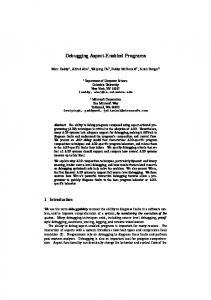
Programmable core [IP block] IN X(N) D(N) = X(N) + D(N-1)A1 + D(N-2)A2 OUT D(N) if DEBUG D(N) = IN Y(N) = D(N)B0 + D(N-1)B1 + D(N-2)B2 OUT Y(N)
Master programmable core signal to start cut-set output
Shared bus Scheduling Logic Debug Buffer
ALU
ASIC core 2
Due to the exponential growth of both design complexity and the number of gates per pin, functional debugging has emerged as a critical step in the development of a system-on-chip. We introduce a novel debugging approach for programmable systems-on-chip. The new method leverages the advantages of the two complementary functional execution approaches, emulation and simulation. We have developed a set of tools, transparent to both the design and debugging process, which enables the user to run long test sequences in emulation, and upon error detection, roll-back to an arbitrary instance in execution time, and switch over to simulationbased debugging for full design visibility and controllability. The efficacy of the approach is dependent on the method for transferring the computation from one execution domain to another. To enable effective transfer of the computation state, we have identified a set of optimization tasks, established their computation complexity, and developed an efficient suite of optimization algorithms.
ulation and emulation of multi-core programmable systems-onchip. The developed approach enables the user to migrate the functional execution of the design back and forth between the simulator and emulator. Long test sequences are run in emulation. Upon error detection, the computation is migrated to the simulation tool for full design visibility and controllability. To explain how execution is transferred from one domain to another, we use the notion of a complete cut. A complete cut is a set of variables which fully determines the design state at an arbitrary time instance [Kir98]. The running design (simulation or emulation) periodically outputs its cuts. The cuts are saved by a monitoring workstation. When a transition to the alternate domain is desired, any one of the previously saved cuts can be used to initialize, and then continue execution with preserved functional and timing accuracy. The debugging paradigm introduces a number of optimization problems and a need for efficient implementation mechanisms. We propose a suite of algorithms which effectively identifies the minimal computation state and post-process the core design and system integration to enable I/O of variables of the identified computation state. We have conducted a set of experiments on standard multicore benchmarks to quantify the overhead induced to enable the developed debugging methodology.
ASIC core 1
ABSTRACT
Register File
Figure 1: The targeted system: core architecture, embedded software, and core integration. 2. HARDWARE AND COMPUTATION MODEL The architecture template used to evaluate the developed debugging method is depicted in Figure 1. The architecture is typical for most modern consumer electronics devices. It contains a set of application-specific (ASIC) and slave programmable cores (SPC) connected to a shared bus. The system is controlled by a single master programmable core (MPC). Each ASIC contains a datapath and/or memory hierarchy.
3. GLOBAL DESIGN-FOR-DEBUGGING FLOW During the design of an application-specific core, debug functionality is added as a post-processing step. This functionality includes a set of register-to-output interconnections and a feature which enables the system integrator to select a specific cut. Since the system architecture is in general not known at the time the applicationspecific core is designed, this subset of interconnects should enable I/O of variables for a large number of candidate cuts. When numerous options exist for selecting a cut, the system integrator will more effectively coordinate the cut I/O. The ASIC developer provides the system integrator with information about the set of cuts. For each cut, the variables and control steps at which each variable can be dispensed through the virtual pins of the ASIC is given. The system integrator faces three design problems. Firstly, for each ASIC a single cut has to be selected. Second, the selected cuts, jointly with the primary input and output, have to be scheduled for I/O over the available set of I/O pins. We integrated these two phases into a tight optimization loop which searches for a feasible solution. In the third step, if no feasible schedule is found, the system-on-chip cut I/O is spread in time by scheduling particular ASIC cuts sequentially. Each PC has, in general, two components in its cut: instructionaccessible states (e.g. general-purpose registers), and states nonaccessible to machine code (e.g. branch prediction hardware). The part of the cut accessible to instructions is I/O using code instrumentation. The portion of the core’s state that is not accessible by instructions must be either reset (e.g. cache flush) or I/O. The debug instructions are instrumented into the object code in a way similar to Purify [Has92]. An example of instrumented code is given in Figure 1. Instructions OUT(D[N]); and if Debug D[N] := IN; are sufficient to enable full controllability and visibility. During the system software development, four subtasks are undertaken. In the first phase the minimal-size cut for each statically scheduled “computational island” is identified. In the second step, the programs are instrumented for cut I/O. In the last two phases, we identify cut variables outside the SDF islands and instrument the non-SDF code running on the MPC and SPCs with instructions which control the system cut I/O. Figure 2 illustrates the technical details of the process of cut I/O. The code instrumentation which runs on the MPC starts the cut I/O. As shown in Figure 2, the MPC first sends a signal (start ASIC) to the ASICs which start their cut I/O. This process is statically scheduled. Cuts of cores ASIC1 (Cut1) and ASIC3 (Cut2) are interleaved and the cut of core ASIC4 (Cut3) is I/O sequentially. Due to static scheduling, the MPC knows when the ASIC cut I/O is complete. If buffering is used to resolve the problem of unscheduled cut variables, the MPC is responsible for explicit I/O of these variables.The MPC, using a round-robin policy, initiates (start SPC(i)) the cut I/O of each SPC. Upon receipt of this
signal the virtual tristate gate that controls the actual I/O of variables onto the shared bus is enabled and the cut I/O starts. The instrumented code running on the SPC has to be able to assure that exactly one cut I/O from each SPC (Cut SPC) is completed. Once its cut is dispensed, the SPC sends a signal back to the MPC which acknowledges one successful cut I/O. Finally, the MPC initiates its own cut I/O, which represents the end of the system cut I/O. SPC
Legend
MPC
ASIC 1
ASIC 3
ASIC 4
IN
MPC instruction that initiates the cut-set I/O Part of the computation at which the core transfers its cut Computation iteration with its primary input and output
IN
start ASC
start PC
IN
PC computation with primary inputs and outputs (bold arrows symbolize CUT output before the MPC has acknowledged it)
Cut 2
Cut 1
Cut 1
A
B
IN
OUT
Cut 3
OUT
IN
A
IN OUT
Cut SPC
Computation in time
We target the following heterogeneous model of computation. The backbone of the model is the semi-infinite stream (SIS) random access machine (RAM) model. The standard RAM model [Aho83] is relaxed by removing a requirement for algorithm termination. The SISRAM model provides high flexibility with well tested and widely used semantics and syntax (C and Java). The second component of the heterogeneous model is synchronous data flow (SDF) [Lee87] which is used for specifying a potentially empty set of statically scheduled islands of computations. This model facilitates optimization-intensive implementation on both ASIC and programmable platforms.
B
Cut MPC
OUT
Figure 2: View at the process of outputting the cut variables of all cores in the system. 4. THE NEW APPROACH: DEBUGGING AUTOMATION 4.1. Programmable Core Cut-Selection The I/O of cut variables on programmable engines is performed by executing debug instructions embedded into the original code by a compilation post-processing tool. The embedded instructions impact the system performance and impose storage overhead. The number of embedded instructions is directly proportional to the cardinality of the selected cut. The added instructions may also impose a timing overhead. These two problems are not identical, since different code segments can be executed with different dynamic frequencies in the SISRAM computational model. Since in Section 5 the timing overhead is shown to be minimal on a variety of applications, we focus our attention on the first problem. PROBLEM: PC CUT SELECTION. INSTANCE: Given a computation represented as directed graph and an integer M . QUESTION: Is there a subset of edges, corresponding to the node outputs Oi ; i = 1::N such that when deleted, leaves no directed cycles in the graph, and that N < M ?
LOOPS times S 6 empty Si 2 S GraphCompaction(Si ) For each node Vi;j Compute Snew = Scc(Si , Vi;j ) OF (Snew) = Snew (1 + �) (Snewi )), i=1 (jSnewi j � Edges where � is random number � 2 f0; S1 2 g Select node Vi;j with minimal OF (Snew (Si ; Vi;j )) Delete Vi;j from Si and S = Snew (Si ; Vi;j ) For each Si 2 S If jSi j = 1 delete Si from S CUT = CUT [ Vi;j If jCUT j < jbestcutj then bestcut = CUT Procedure GraphCompaction(Si ) For each vertex Vi 2 Si If Vi has one input edge Ej;i with a source in vertex Vj For each edge Ei;k Create edge Ej;k and delete Ei;k Delete Ej;i and Vi Repeat CUT = null While = For each
P
j
j
j
j
Figure 3: Pseudo-code for PC CUT SELECTION search.
This problem is NP-hard since there is one-to-one mapping between its special case, when all operations in the computation are executed exactly the same number of times, and the FEEDBACK ARC SET problem [Gar79]. For this problem, we have developed a heuristic summarized in Figure 3. Initially, the computation CDFG is partitioned into a set of strongly connected components (SCCs) using a breadth-search algorithm [Cor90]. All trivial SCCs, which contain exactly one vertex, are deleted from the resulting set because they do not form cycles. Then, for each SCC several processing steps are performed. Firstly, to reduce the solution search space, a graph compaction step is performed. Each B which contains only vertices V 2 P; V 6= A path P : A with exactly one input variable is replaced with a new edge EA;B which connects the source A and destination B . Secondly, for each node V in the graph an objective is established. The objective evaluates the cardinalities of the newly created SCCs in the remaining graph when V is deleted. The node that has the smallest objective is deleted from the graph and added to the resulting cut. The described process is repeated until the set of nontrivial SCCs in the graph is empty.
;
4.2. ASIC Cut Selection The debugging strategy comprises two modular phases, conducted by two parties in the system development process: the core provider and system integrator. The core developer selects a minimal number of register-to-output interconnects such that large number of complete cuts are available to the system integrator. An additional constraint is set on the timing occurrence of these cuts. Since the core developer does not know in advance the multi-core system configuration, its search for a set of register-to-output interconnects is targeted for large number of non-overlapping small cuts. Such subset of registers enables the system integrator to have flexibility in finding a solution to the cut scheduling problem. The definition of a debugging register subset forces selection of registers which define a large cardinality set of cuts with small cardinality, long life-times of containing cut variables, and nonoverlapping life-times of variables in the set of cuts. The core developer faces an optimization problem to find a subset of registers with the smallest possible constants Max and K .
PROBLEM: DEBUGGING REGISTER SELECTION. INSTANCE: Given a scheduled CDFG, and integers MinOF and MinCard. QUESTION: Is there a subset of registers Ri ; i = 1::Rm that determines a set of m distinct CDFG cuts Ci ; i = 1::m, and has OF (Ci ; i = 1::m) < Min and Rm < MinCard?
Heuristic definition 1. A “debugging register subset” is a subset of registers Ri ; i = 1::Rm which defines a set of m distinct cuts Ci ; i = 1::m that satisfies the following two statements:
Ci ; i ::m PRmmi< PMaxV C OFLifeTime i Pmi Ci P CtrlStepC LiveV Vars C and
=1
(
=1
j
j)�(
8
8
2
(
=1 2(
)=
)
2(
))
< K,
where function LiveV ars(C ) returns the number of variables alive at control step C , K is a given real number, and m; Max; Rm are given integers. A special case of this problem, with no register sharing among CDFG computation variables and no additional heuristic requirements, is NP-hard since it is equivalent to the FEEDBACK ARC SET problem [Gar79]. We have developed a heuristic to search for a debugging register subset in a scheduled and assigned CDFG. The algorithm is formally explained using the pseudo-code in Figure 4. The algorithm first partitions the CDFG into a set S of
SCCs. Then, for each register Ri , an objective function evaluates the set of SCCs Snewj 2 Snew which are result of deletion of all variables held by register Ri . The objective function used to quantify the register selection is: OFR(R; SR; cdfg ) =
P LiveV ars P V CtrlStepC LifeTime V R
Scar(R;cdfg)�
C;SR)
2(
8
2(
)
, where
Scar returns
the sum of squares of cardinalities of the set Snewi of SCCs created when all variables held by R are deleted from the CDFG. LiveV ars returns for control step C , the sum of squares of number of variables alive at C and held by the currently selected subset of registers SR. The register with the highest objective function is selected, added to the currently selected subset of registers SR, and all its variables are deleted from the original CDFG. The process of register selection is recursively repeated while the set of nontrivial SCCs is not empty. 8
2
LOOPS SR S 6 empty R 3 SR Snew Scc cdfg , E jE 2 R R OFR R ; SR; cdfg Rk from Si SR SR [ R S Snew S ; E jE 2 Rk ) S 2 S jS j S S OF SR > OF BESTSR BESTSR SR
Repeat times Starting set of registers = null While = Foreach register i Compute = ( i;j i;j i) Select the register k which results in minimum ( k ) and delete all variables held by = ( i i;j i;j k and = For each i If i = 1 delete i from If ( ) ( ) then =
Figure 4: Pseudo-code for the debugging register subset search. 4.3. Multi-ASIC Cut Selection and Scheduling We introduce an algorithmic solution which enables I/O of cut variables from multiple statically scheduled ASICs. We use the common multiple (CM ) of all as the system debugging period. Within this period the algorithm tries to find a feasible schedule of variables of all ASIC cuts such that the range of control steps is minimal between the moments when the first and last variable in the ASIC subsystem cut is output. PROBLEM: CUT SELECTION AND SCHEDULING. INSTANCE: Given a set of cores ASIC , a set of cuts CUTCore for each core Core ASIC , a set of variables V for each cut C CUTCore , a set of control steps CSv for which each variable v V is alive, a set of CS control steps at which chip ports are idle, and integer f for MaxRange. QUESTION: Is there a selection f of a cut CUTCore f each core, such that for each variable v CUTCore exists a distinct control step CSvf CS at which the chip port is idle, no two variables f ; w CUT f f v CUTCore 1 Core2 are scheduled for transfer CSv = f CSw through the chip port at the same idle control step, and that the max(CSvf CSwf ) < MaxRange ?
2
2
2
,
2
2
2
2
6
The NP-complete problem of scheduling a subset of variables in a CDFG [Kir97] is a special case of this problem. We developed a most-constrained least-constraining heuristic described using the pseudo-code in Figure 5. Initially, for each ASIC, the available cuts are sorted in decreasing order with respect to the average lifetime of contained variables. The selection and scheduling search loop selects one cut for each ASIC from its list of available cuts. Cuts that contain variables with longer average life-times are given priority. Next, within CM consecutive control steps, the subset of M consecutive control steps in which the variables of the selected cuts can be scheduled. The search is initiated by determining the lower bound on the range of control steps M = Mmin for which all cuts can be dispensed. This bound is equal to the sum of the cardinalities of all ASIC cuts. Then, within CM consecutive control steps, a set T is found where each element Tp 2 T represents a subset of Np consecutive control steps which contains at least
Mmin idle control steps, and for each variable of all cuts there must be at least one idle step in which it is alive. For each combination of cuts within Tp , a scheduling heuristic is performed. The scheduling heuristic iteratively constructs the solution by selecting N most-constrained cut variables and scheduling them exactly at the N least-constraining control steps. If feasible scheduling is found, the range of the solution Np is compared to the best current solution. Otherwise, the control step range M is increased and the search procedure is repeated. Cut Selection Preprocessing: For each i Create a list i of cuts i;j in decreasing order of average life-time of contained variables. Cut Selection: Repeat times For each i Select one cut i;j i where is an index selected among all other indexes with probability proportional to the square of average life-time of variables in i;j jASIC j = . i;j i=1 Repeat Find the set of idle consecutive control steps in the CM of periods of all ASICs which contain the cuts of all i;j . For each p For each subset of cuts of each ASIC encompassed with Schedule i;j in p . If schedule found and in shorter time than the best schedule then best schedule = current schedule. until ++ == . Cut Scheduling: [Schedule i;j in p ] Repeat until all variables scheduled For each control step i and variable alive at i 1 compute its constraint i as sum of V:lifetime For each variable i compute its constraint i as sum of constraints of control steps at which i is alive. Select the most-constrained tasks and exactly schedule them at control steps with the smallest sum of their constraints.
ASIC L
CS
LOOPS ASIC CS 2 L
Range
P
j
CS
jCS j
T Range T 2T jASIC j CS T
Range
N
CS
5. EXPERIMENTAL RESULTS We have conducted a set of experiments to evaluate the effectiveness of our system debugging paradigm. Table 1 shows experimental results for the ASIC design-for-debugging technique. All designs were synthesized using the HYPER system [Rab91]. Columns 2 - 6 of Table 1 present the iteration period in control steps, the number of variables in the computation, and total area. Column eight presents the number of variables in the smallest cut, broken down into I/O and non-I/O cut variables. Finally, the last column shows the area overhead (OH). Variables 51 53 53 57 50 86 50 40
Area
mm2 )
(
3.88 5.69 12.68 4.67 2.79 15.40 5.46 1.88
Cut size 2+4 2+8 2+1 2+4 2+1 5+0 5+0 2+1
System period
Cut size
Lin3 (T=10), Lin3 (T=15), Cont. Fraction Cascade, Dir. Form II, Parallel (T=10), Mat, Ellip Cont. Fraction, Mat, Dir. Form II, Modem Parallel (T=10), Modem, Dir. Form II, Cascade Parallel (T=9), Ellip, Lin3 (T=10), Volterra Parallel(T=9), Lin3(T=10), Lin3(T=15), Volterra
22 31 21 19 21 25
21 24 20 18 19 20
Application ADPCM.enc ADPCM.dec D/A Converter G721.enc.dec PGP GSM.enc.dec JPEG.enc MPEG2.dec
Tp
> BestRangeorRange jLCM j CS T C V C C :constraint V V :constraint V
T 14 19 10 10 20 10 15 15
Application-specific core mix
Steps to I/O the cut 22 27 20 18 20 23
Table 2: Efficiency of the cut selection and scheduling.
Figure 5: Pseudo-code for the cut selection and scheduling.
ASIC Cascade CF IIR Dir. Form II Parallel Modem Lin3 Ellip Volterra
Table 3 presents results that evaluate the feasibility and overhead of programmable core design-for-debugging. Applications were taken from the MediaBench benchmark suite [Lee97]. Columns 2 - 4 quantify the total number of variables in the program, the cardinality of the program cut, and the ratio of cut size to total variables. The last column determines the upper bound on the overhead on the program execution performance. Note that this overhead is negligible during emulation since system emulation is orders of magnitude faster than system simulation.
Area OH 2 ( ) 0 0 0 0 0.01 0 0 0.06
mm
Table 1: Debug information for the ASIC implementation. Table 2 presents the experimental results which demonstrate the efficiency of our multi-ASIC cut-selection and scheduling technique. Column 2 - 4 present the resulting system period, the number of variables in the system cut, and the range of control steps in which the cut transfer is accomplished. By comparing these two columns, it is clear that the available system I/O-idle control steps are efficiently utilized to I/O interleaved cuts.
Variables 22 13 213 28 970 140 513 432
Cut size 6 5 3 2 33 12 17 24
% of Vars for cut I/O 27% 38% 1.4% 7% 3.4% 8.6% 3% 5.5%
Table 3: Cut selection for programmable machines. 6. CONCLUSION We have presented the first debugging approach for programmable systems-on-chip that coordinates emulation and simulation. We have developed design-for-debugging algorithms for code instrumenting with cut I/O instructions and an optimization methodology for efficient cut scheduling of a set of ASICs on a shared bus. The effectiveness of the approach is demonstrated on a set of programmable and ASIC multi-core designs where full system observability and controllability have been enabled with low hardware and performance overhead. 7. REFERENCES [Aho83] [Apt98] [Cor90] [Gar79] [Has92] [Iko98] [Int98] [Kir97] [Kir98] [Lee87] [Lee97] [Man97] [Mar98] [Mau86] [Qui98] [Rab91] [Syn98] [Yan95]
A.V. Aho et al. Data structures and algorithms. Addison-Wesley, 1983. http://www.aptix.com:80/Products/mp4.html. T.H. Cormen et al. Introduction to Algorithms. The MIT Press, 1990. M.R. Garey and D.S. Johnson. Computers and intractability: a guide to the theory of NP-completeness. W. H. Freeman, 1979. R. Hastings and B. Joyce. Purify: fast detection of memory leaks and access errors. USENIX, pp.125-136, 1992. http://www.ikos.com. http://www.interrainc.com/picasso.html. D. Kirovski, M. Potkonjak, Quantitative Approach to Functional Debugging. International Conference on Computer-Aided Design, pp.170-4, 1997. D. Kirovski et al. Functional Debugging of Systems-on-Chip. Technical report, CSD, UCLA, 1997. E.A. Lee and D.G. Messerschmitt. Static Scheduling of SDF Programs for DSP. Trans. on Computers, vol.36, no.1, pp.24-35, 1987. C. Lee et al. MediaBench: A Tool for Evaluating and Synthesizing Multimedia and Communications Systems. IEEE Micro 30, 1997. S.T. Mangelsdorf et al. Functional verification of the HP PA 8000 processor. Hewlett-Packard Journal, August 1997. J. Marantz. Enhanced Visibility and Performance in Functional Verification by Reconstruction. DAC, pp.164-9, 1998. C. Maunder. JTAG, the Joint Test Action Group. IEE Colloquium on New Ideas in Testing, pp.6/1-4. 1986. http://www.quickturn.com/prod/hdlice/hdlice.htm. J. Rabaey et al. Fast Prototyping of Datapath-Intensive Architectures. Design and Test of Computers, vol.8, no.2, pp. 40-51, 1991. http://www.synopsys.com/products/simulation/cyclone cs.html L. Yang et al. System design methodology of UltraSPARC-I. DAC, pp.7-12, 1995.