Department of Electrical and Electronics Engineering, TKM College of Engineering, Kollam. Abstract. To meet the future energy requirement and to give.
Fuzzy Logic Based Maximum Power Point Tracker for a Photovoltaic System 1
2
Vipin Padmanabhan , Beena V and Jayaraju M
3
1. Department of Electrical and Electronics Engineering, Thejus Engineering College, Thrissur 2. Department of Electrical and Electronics Engineering Government Engineering College, Thrissur 3. Department of Electrical and Electronics Engineering, TKM College of Engineering, Kollam Abstract To meet the future energy requirement and to give quality and pollution free supply to growing and environment conscious population, the present world is giving special attention to natural, clean and renewable energy sources. Due to growing demand for electrical energy and environmental issues such as pollution and global warming effect, solar energy is considered among one of the best options for generating clean energy. In this paper a fuzzy logic controller (FLC) is used as an intelligent method for Maximum Power Point Tracking (MPPT) for a Photo Voltaic (PV) system. Fuzzy logic has been used for tracking the Maximum Power Point of PV systems because it has the advantages of being robust, relatively simple to design and does not require the knowledge of an exact model
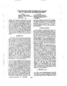
temperature and insolation level. To overcome these problems MPPT (Maximum Power Point Tracker) is used. In this paper, an intelligent control technique using fuzzy logic control is associated to an MPPT controller in order to improve efficiency of PV system. II. Solar Cell Model A model which is electrically equivalent to that of a solar cell is shown in figure 1. From the equivalent circuit it is evident that the current produced by the solar cell is equal to that produced by the current source, minus that which flows through the diode, minus that which flows through the shunt resistor [3].
Keywords: Fuzzy Logic Controller (FLC), Maximum Power Point (MPP), Maximum Power Point Tracking (MPPT), MPPT algorithms and Photovoltaic.
I.
I
INTRODUCTION
n order to solve energy crisis and environmental
pollution, renewable energy has been the certain choice of sustainable development for mankind. Photovoltaic energy is one of the most popular renewable sources since it is clean, inexhaustible and requires little maintenance. As the conventional energy sources are diminishing fast, the solar energy offers a very promising alternative, because it is free, abundant, pollution free and distributed throughout the earth [1]. In these days of increasing environmental concern, every nation is working to maximize the use of renewable energy resources. There is a growing recognition of the valuable role that solar power can play in reducing pollution.
So we can mathematically express the current produced by the solar cell as, I = IL − ID − ISH, where I = output current (amperes), IL = source current diode current (amperes) (amperes), ID = ISH = shunt current (amperes).
However, the use of PV technology meets several challenges such as increasing the efficiency of PV conversion, ensuring the reliability of power electronic converters etc [2]. Another drawback of PV system is that it does not provide a constant energy source because its output power changes with
PV modules have unique current v/s voltage (I-V) characteristics. From the P-V and I-V characteristics, as shown in figure 2, it is clear that the PV systems must be operated at a maximum power point (MPP) of specific current and voltage values so as to increase the PV efficiency [4]. The voltage that
Fig. 1. Electrical equivalent model of solar cell
978-1-4673-0449-8/12/$31.00 ©2012 IEEE
corresponds to the module maximum power varies with temperature and insolation variations, so a MPP tracking system is needed to ensure that we stay as close as possible to the maximum power point.
Photovoltaic (PV) modules in a manner that allows the modules to produce all the power they are capable of. MPPT is not a mechanical tracking system that “physically moves” the modules to make them point more directly at the sun. MPPT is a fully electronic system that varies the electrical operating point of the modules so that the modules are able to deliver maximum available power. IV.MPPT ALGORITHMS
Fig. 2. P, I v/s V curve
III. MPPT (MAXIMUM POWER POINT TRACKING) For any PV system, the output power can be increased by tracking the MPP (Maximum Power Point) of the PV module by using a controller connected to a dc- dc converter (usually boost converter). However, the MPP changes with insolation level and temperature due to the nonlinear characteristic of PV modules. Each type of PV module has its own specific characteristic. In general, there is a single point on the V-I or V-P curve, called the Maximum Power Point (MPP), at which the entire PV system operates with maximum efficiency and produces its maximum output power. This point can be located with the help of MPPT (Maximum Power Point Trackers) [5]. PV system with MPPT controller has been shown in figure 3.
Fig. 3. PV system with MPPT
Maximum Power Point Tracker, frequently referred to as MPPT, is an electronic system that operates the
Various algorithms have been proposed for tracking MPP in the past. Commonly used algorithms are Perturb and observe method, Incremental conductance method, Constant voltage method, Constant Current method etc. Perturb & observe method is also known as P&O method. In this method voltage or current of the PV array is modified to reach the MPP. For example the voltage is kept on increasing till the power increases. Constant voltage method is one of the simplest algorithms for MPPT. This method is based on the fact that the ratio of the array’s maximum power voltage, VMPP, to its open-circuit voltage, Voc, is approximately constant. Constant current method is similar to constant voltage method [6]. V METHOD FOR MPPT TRACKING Usually MPPT algorithms are based on the comparison of average values of Ipv and Vpv. The MPPT scheme here employs a peak current controlled boost dc-dc converter [7]. The output of the MPPT algorithm is the current reference for the peak current controller. By comparing instantaneous values of PV voltage and current at two different sampling instants, the variation of the reference current that would result in an increase of PV output power can be obtained. The basic principle for the operation of the MPPT algorithm can be explained as follows based on Figure 4. Let us suppose the system is operating on the left side of the MPP and the average value of the PV current rises due to an increase in the reference current. In every switching cycle, Ipv increases during switching on and decreases during switching off because of the boost converter. If the sampling time instant in switching cycle T(k-1) is at point A and the sampling time instant in switching cycle T(k) is at point B, the instantaneous current at A, IA, is less than the instantaneous current at B, IB. It can be seen from Figure 4(b) that the instantaneous power at A, PA, is less than the instantaneous power at B, PB. Therefore, since a positive variation of the instantaneous current resulted in a positive variation of the instantaneous PV power, the reference current
Iref should be increased. One can also conclude, from the MPPT algorithm, that the operating point is on the left side of the MPP and that the reference current Iref should be increased to drive the operating point towards the MPP.
The inputs to the Fuzzy controller are change in PV array Power (ΔPPV) and change in PV array current (ΔIPV) corresponding to the two sampling time instants. The two inputs are processed by the Fuzzy controller and the output of the Fuzzy controller is the incremental reference current (ΔIref). This output is given to the Boost converter. Thus during transient conditions the Fuzzy logic controller outputs a larger incremental reference current to speed up the transient response but outputs almost zero incremental reference current near the peak power region to reduce oscillations about the MPP. Fuzzy algorithm tracks the maximum power based on the master-rule: "If the last change in the reference current (ΔIref) has caused the power to increase keep changing the reference current in the same direction; else if it has caused the power to drop, move it in the opposite direction”.
Fig. 4. Operating point on left side of MPP a)Ipv wave form in two switching cycles (b) Ipv locus on PI curve
If the sampling time instant in switching cycle T (k) is at point C instead of point B, the instantaneous samples show that IC is less than IA and that PC is less than PA. It is clear that with reduction in current value, the power also reduces hence the reference current Iref should be increased. VI.FUZZY LOGIC CONTROLLER Recently fuzzy logic controllers have been introduced in the tracking of the MPP in PV systems. They have the advantage to being robust and relatively simple to design as they do not require the knowledge of the exact model. They do require in the other hand the complete knowledge of the operation of the PV system by the designer. A fuzzy logic controller basically includes – Fuzzification, Rule base, Inference method and Defuzzification method.
Fig. 6. Input and output membership functions
Fig. 5. FLC controller
The universe of discourse for input variable 1 (ΔPpv) is divided into seven Fuzzy sets: PB (Positive Big), PM (Positive Medium), PS (Positive Small), ZZ (Zero), NS (Negative Small), NM (Negative Medium) and NB (Negative Big). The universe of discourse for input variable 2 (ΔIpv) is divided into 3
Fuzzy sets: N (Negative), Z (Zero) and P (Positive). The universe of discourse for the output variable (ΔIref) is divided into 7 Fuzzy sets: PB (Positive Big), PM (Positive Medium), PS (Positive Small), ZZ (Zero), NB (Negative Big), NM (Negative Medium) and NS (Negative Small). The two inputs are processed by the Fuzzy controller and the output of the Fuzzy controller is the incremental reference current (ΔIref), which varies in magnitude and polarity depending on which region of the Ppv v/s Ipv curve, the system is operating on. The output is the reference current to the Boost converter.
Fig. 8. Matlab model for PV system
WITHOUT MPPT CONTROLLER (Insolation level- 600W/m.sq)
Fig. 7. PV System with MPPT
VII.SIMULATION & RESULTS The simulation of the PV system was carried out in MATLAB/Sim Power Systems environment. The solar array was simulated first and the results for various values of insolation were obtained. The table I shows the maximum power corresponding to particular insolation level.
Fig. 9(a). Solar array and boost converter current
TABLE I Maximum power corresponding to particular insolation level.
INSOLATION LEVEL (W/m2) 600
MAXIMUM POWER (WATTS) 47.47
700
55.88
800
64.32
900
72.79
1000
81.27
The PV model was simulated and the results of simulation for PV system with and without MPPT system have been shown in figure 9, 10 and 11.
Fig. 9(b). Solar array and boost converter voltage
Fig. 9(c). Solar array and boost converter power
WITH MPPT CONTROLLER (Insolation level- 600W/m.sq)
Fig. 10(c). Solar array and boost converter power
Power output for varying insolation levels
Fig. 10(a). Solar array and boost converter current Fig. 11. Solar array and boost converter power
VII.CONCLUSION
Fig. 10(b). Solar array and boost converter voltage
In this paper, a Photovoltaic system with an intelligent Maximum power point tracker (MPPT) has been modeled using Matlab software. The algorithm used for MPPT controller is based on Fuzzy Logic. Fuzzy logic controller is modeled using fuzzy toolbox in MATLAB. The entire PV system was simulated and simulation results are verified. From the results it was clearly found that the PV system becomes more efficient when a MPPT controller is included in the system when compared to a PV system without MPPT controller. Hence it has been proved that the designed controller, with the adequate choice of the membership functions, can make sure that the MPPT will follow the true MPP and thereby the overall efficiency of the PV system can be improved.
REFERENCES 1.
2.
3.
4.
5.
6.
7.
8.
9.
Kimiyoshi Kobayashi, Hirofumi Matsuo and Yutaka Sekine, “A novel optimum operating point tracker of the solar cell power supply system” ,IEEE Conference on Power Electronics, Volume 3, 20-25 June 2004 ,Page(s):2147 - 2151 Vol.3. M.Godoy Simdes and N.N.Franceschetti, “Fuzzy optimisation based control of a solar array system”, IEE Proc.-Electr. Power Appl., Vol. 146, No. 5, September I999, IEE Proceedmgs online no. 19990341 M. G. Villalva, J. R. Gazoli, and E. R. Filho “Comprehensive Approach to Modeling and Simulation of Photovoltaic Arrays” IEEE Trans. Power Electr., vol. 24, no. 5, pp. 1198-1208, May 2009. Y.Kuo-“Maximum Power Point Tracking controller for photovoltaic energy conversion system”-IEEE Trans Ind. Electron-Volume 48-2001. Nicola Femia, Giovanni Petrone, Giovanni Spagnuolo, Massimo Vitelli “Optimization of Perturb and Observe Maximum Power Point Tracking Method” IEEE transactions on power electronics, vol. 20, no. 4, july 2005 D. P. Hohm and M. E. Ropp, “Comparative Study of Maximum Power Point Tracking Algorithms”, Progress in photovoltaics: research and applications Prog. Photovolt: res. Appl. 2003; 11:47–62 (doi: 10.1002/pip.459) Xuejun Liu and Luiz A. C. Lopes , “An Improved Perturbation and Observation Maximum Power Point Tracking Algorithm for PV Arrays”, 2004 35th Annul IEEE Power Electronics Specialists Conference Chung-Yuen Won, Duk-Heon Kim, Sei-Chan Kim “A New Maximum Power Point Tracker of Photovoltaic Arrays Using Fuzzy Controller”, IEEE transaction 1994 S. Armstrong and W.G Hurley “Investigating the Effectiveness of Maximum Power Point Tracking for a Solar System”, IEEE Conference on Power Electronics, 2005 Page(s):204 – 209.