1
General Modeling of Multi-Terminal VSCHVDC Systems for Transient Stability Studies Paulo J. D. Chainho, Arjen A. van der Meer, Madeleine Gibescu, Ralph L. Hendriks, Mart A. M. M. van der Meijden Future transmission systems will contain more dc structures. Their effects on ac power system transient stability may become significant and should hence be studied in detail. However, traditional stability simulation software is not designed to simulate transient effects in dc systems creating the need for user-defined modeling. This paper describes a general modeling method for including multi-terminal high-voltage dc systems based on voltage sourced converters into stability-type simulations. The method employs a state-space representation of the relevant network elements and connected devices. A Pythonscripted load flow method for dc initializes the network model. The modeling framework has been designed for inclusion into PSS®E. Throughout the paper, issues closely connected to this implementation are being dealt with. The method has been tested on a scheme containing both ac and dc networks. Results show a good dynamic coupling between the stability simulation and the developed dc network model. Index Terms— transient stability simulations, VSC-HVdc, multi-terminal, offshore wind, PSS®E.
I. INTRODUCTION FFSHORE wind power is gaining interest from policy makers around the world as a viable renewable energy alternative. Scenarios by the European Wind Energy Association foresee 40 GW of installed offshore wind power in Europe by 2020 and 150 GW by 2030 [1]. The large installed capacity as well as their envisaged (remote) locations make the grid connection of offshore wind power plants (WPP) challenging. Meanwhile, a persistently growing need for international trading capacity can be observed, for instance in Western Europe. High-voltage dc transmission based on voltage sourced converters (VSC-HVdc) is regarded as a promising technology for achieving both international trade and connection of far and large offshore WPPs. Particularly the ability to build and operate VSC-HVdc in multi-terminal mode (VSC-MTdc) can be regarded as a significant merit for
O
This research is financially supported by AgentschapNL, an agency of the Dutch Ministry of Economic Affairs, under the project North Sea Transnational Grid (NSTG). NSTG is a joint project of Delft University of Technology and the Energy Research Center of the Netherlands. P. J. D. Chainho is with the Department of Electrical and Computer Engineering, Technical University of Lisbon, 1049-001, Lisboa, Portugal (email:
[email protected]) A. A. van der Meer, M. Gibescu, R. L. Hendriks, and M. A. M. M. van der Meijden are with the Electrical Sustainable Energy Department, Faculty of Electrical Engineering, Mathematics, and Computer Science, Delft University of Technology, 2628 CD, Delft, the Netherlands (e-mail: A.A.van
[email protected],
[email protected],
[email protected],
[email protected])
offshore applications. Such high amounts of dc-connected generation may seriously influence generator dispatching and even unit commitment in the onshore power system. Consequently, the total amount of rotating inertia in operation may be decreased during high-wind conditions. Since VSCHVdc schemes inheritly do not contribute to the power system inertial response, power system transient stability may be affected. The consequences of grid connection of VSC-MTdc schemes on transient stability should therefore be studied in detail. These studies are traditionally conducted with time domain simulation tools designed for computing dynamics of large-scale ac systems, which use simplified device modeling and a quasi steady-state ac network representation by phasors. In order to properly include events in the dc grid or interconnected WPPs, the MTdc dynamics should be included. As stability-type simulation tools do not inherently offer this functionality, a user-defined model structure should be used for assessing VSC-MTdc schemes. In PSS®E, for instance, no general VSC-MTdc model exists besides the available twoterminal model [2]. ABB offers a model of their VSC-HVdc technology (HVDC Light) for PSS®E, which was applied in [3]. However, dc system modeling for stability simulations in general is not extensively reported in public literature. This paper introduces a method to include arbitrary MTdc structures and their corresponding electro-magnetic interactions into stability simulations. The paper will describe the general dc system modeling approach and the corresponding interface with the stability simulation (i.e. the VSC modeling). The contribution of this paper lies in the flexibility offered by the proposed dc grid modeling framework which allows coupling of multiple asynchronous ac systems. Particular attention will be given to the implementation of various aspects of the developed model into PSS®E. The paper is organized as follows. First, the VSC model and its role as an interface between the stability simulation and the MTdc network model is described. The paper continues with a derivation of the state-space model of the MTdc grid and the corresponding initialization of the state vectors. The VSCMTdc model is implemented into PSS®E and tested using an example system facing wind power variations and onshore short circuits. The paper ends with conclusions and directions for future work.
2
U s Us e js
Ic
Uc * uabc
U c U s I c jX c *
Pdc Pac
Us
Ic
I c id* jiq* e js *
Fig.1. Schematic representation of VSC model and vector control scheme [4]
Fig. 2. Averaged VSC model used for transient stability studies, with the single-phase equivalent ac and monopole equivalent dc representation.
II. MODELING FRAMEWORK Uc
Stability simulations rely on a well-developed set of assumptions, of which the ones relevant to the context of this paper include:
jX c I c
uy
Network elements are modeled by their fundamentalfrequency complex impedance Network quantities (voltages, currents) are represented by time-varying phasors Device dynamics are modeled to reflect their effects on transient stability (i.e. faster transients neglected) Connected devices are commonly modeled into the algebraic network solver by time-varying current or voltage sources
While these considerations allow simulating large systems at time-step sizes typically ranging from 1 to 10 ms, the type of transmission system to be simulated is limited to ac only. Yet, to include VSC-HVdc transmission systems, a dc network model is defined in this section. It includes the following submodels: 1. 2. 3.
Grid-side VSC (GSVSC) model Wind park-side VSC (WPVSC) model Multi-terminal dc (MTdc) transmission model
The VSC models form an interface between the ac network solver and the developed dc model. The time constants in the dc system are small, but shall not be neglected because the transients inside the dc-network could have an influence on the ac system transient stability. A downside of this approach is the need to reduce the time-step size for the entire dynamic simulation into the μs range. A. VSC Model The basic operating principle of VSCs stems from the semiconductor ability to perform fully controllable switching at a high-frequency. Together with an appropriate modulation
Us id
s ux
iq
Fig. 3.
Ic
Phasor diagram of the VSC model with network and d-q frame
technique (such as PWM), VSCs can create voltages with specified amplitude and phase shift. Typically, a cascaded control structure based on vector control is used to provide the converter output voltage, allowing independent control of active and reactive power. This control structure consists of a fast inner controller that regulates the converter output current, a set of outer controllers that determine the current set points depending on the control options, and a phase-locked loop that synchronizes the d-axis component of the control scheme with the voltage at the point of common coupling (PCC). The VSC model and control structure is schematically represented in Fig. 1. Detailed considerations about this type of VSC modeling and control can be found in [5,6]. 1) Simplifications for stability studies The main focus here is transient stability, therefore, controls having a bandwidth higher then the phenomena of interest (e.g. 0.1–10 Hz) can be safely disregarded or simplified. For VSCs, this translates into the following assumptions:
The control system tracks the PCC voltage perfectly Converter voltage reference values are reached instantly.
The former assumption entails that the PLL, the current controller, and the modulation system can be included by simplified to first-order delay elements or neglected at all.
3 Fig 2 shows the network, converter, and controls representation around the VSC connection point. Decoupled control of active and reactive power is achieved by employing the d-q reference frame as shown in Fig 3. Applying this, the converter output equals
U s u x ju y ud e
j s
in which U s and I c are the PCC voltage phasor and converter current in the network (x-y) reference frame respectively. Active and reactive power can now be controlled by
Pac* ud id* (3) * * Q ud iq id* and iq* are the active and reactive current set points.
The converter voltage is now determined by
U c U s Ic jX c
(4)
The converter is assumed lossless, enabling modeling as a variable current source at the dc side of the converter according to
Pdc Pac idc
id ud udc
(5)
2) GSVSC (grid side voltage source converter): The main duty of the GSVSC is to control the power exchange between the dc and ac grid. As deviations in the direct voltage are a measure for imbalance in the dc system power dispatch, it is used as an input to the vector control scheme. The outer controllers are responsible for providing the current set points and regulate the direct voltage and the PCC voltage amplitude by
1 * * * id K d udc udc udc udc dt d iq* K q U s * U s 1 U s * U s dt q
(6)
The VSC’s semiconductor switches have a maximum current capability, which is modeled here by curtailing the 2
I Norton
(1)
I c ix ji y id jiq e js (2)
Where
Ic Us
2
current set points whenever id* iq* I clim . This readjusting can be done with different strategies [7], of which proportional scaling is applied here. 3) WPVSC (wind park voltage source converter): The main requirement of the WPVSC is to absorb all the wind power produced by the WPP. To achieve this, the WPVSC should behave as a controlled voltage source rather than a controlled current source. Hence, the outer controllers regulate the converter voltage amplitude |Uc| through a PI controller that uses as input the error between the set point and measured values of the ac voltage at the WPP by
Fig. 4. [2]
U c* jX c
Z Norton jX c
PSS®E generator model equivalent used for the ac network solution.
*
U c Ku U s U s The angle of
1
u
U
* s
U s dt U c
0
(7)
U c , c , is kept constant in normal operation.
4) WPP fault-ride through Onshore faults present an operational challenge for VSCHVdc systems. GSVSCs will hit their current limits due to the voltage dips associated with onshore faults. Meanwhile, the WPVSCs behave as power sinks for the connected offshore WPPs. As a consequence, more energy is injected into the dc grid than drawn from it, leading to a quick rise of the direct voltage. Several methods have been proposed to deal with this issue [8]. Here, a chopper-controlled braking resistor is connected at the dc terminals of each GSVSC. This protection system is triggered after an elevated direct voltage is detected and is modeled by a variable resistance Rbr as discussed in [9]. 5) Representation in PSS®E In this study, PSS®E was used to implement the modeling framework. It employs a current injection based solver for the network equations, where the equivalent circuit used to represent a generator is the Norton equivalent of a controlled voltage source behind an impedance. The ac side of the VSC averaged model presented in Fig. 2 uses is hence modeled in PSS®E as a Norton-equivalent current injection (Fig. 4). Rearranging (4) and implementing (6) and (7) gives the timevarying Norton current injection for each type of VSC control U s jX c id* jiq* e js if GSVSC * jX c (8) Uc I Norton * j * c Z Norton Uc e if WPVSC jX c B. Multi-Terminal DC Network model In order to create a generic representation of the dynamics of a multi-terminal dc network, three issues need to be considered: dc network topology, dc cable representation, and a scheme to solve the algebraic and differential equations. This model uses an incidence matrix to represent the network topology and a π-section equivalent to represent each cable system. Based on this, a state space representation of the dc network can be compiled [10]. 1) State-space representation By converting the network element dynamics using the Laplace transformation and linear network analysis a set of first order differential equations is obtained, which adequately represent the relevant electro-magnetic transients of the dc
4 network. Re-arranging these equations creates a state space model representation of the system by
dx
Ax Bu
u1dc
udc2
in which j T 1 2 i 1 2 x udc , udc , , udc | ibr , ibr , , ibr
A12 i j A22j j
Bi11i B 21 B ji
(12)
With the sub-matrixes being defined as
1 1 1 GSVSC , ,, R C1 C2 Ci 1 1 1 12 A diag , ,, M C1 C2 Ci
(9)
A diag 11
1 1 1 A21 diag , , , L L Lj 1 2
T M
(10) (11)
Note that the ground node was taken as the reference node and cable and VSC capacitive branches are not included in M. The presented approach allows easy (computer aided) network modeling. 2) MTdc model initialization As usual, initial conditions must be provided before timedomain simulations can begin. The presented initialization method is based on the sequential ac/dc load flow algorithm presented in [11]. Fig. 5 shows the MTDC representation in power flow studies. In the ac power flow, the WPVSCs are included as slack nodes owing to their behavior as a power sink for the WPP. Onshore, the VSCs can be any type of load flow node; here the GSVSCs are modeled as PV nodes. As no reactive power is defined for dc, the number of unknown variables decreases and VSCs can be modeled as P nodes (by setting the dc power injection) or V nodes (by setting the direct voltage). In the presented analysis, one GSVSC is picked as a dc slacknode by setting the direct voltage to its nominal value. The load flow for dc is modeled as follows. The nodal current injections at steady-state can be calculated by
1 1 1 B11 diag , ,, Ci C1 C2
(13)
with I dc idc1 ,idc2 ,,idci the vector containing nodal current
B 0 jxi
(14)
2 i injections, U dc u1dc ,udc ,,udc
I dc Ydcn U dc
1 Rbrm
if m n and node m has a GSVSC
0 0
if m n for other dc nodes if m n
M i, j
1 if j connects to i 1 if j connects from i 0 otherwise
T
the vector with dc node
n
voltages, and Ydc the i x i nodal admittance matrix defined by
Ydcn MYdcbr M T
Ci is the sum of the capacitances connected to node
and M is the directed incidence matrix defined by
(15)
T
1 1 1 = M diag , ,, M T R j R1 R2
i, RGSVSC contains the terms relevant for the braking resistors and is given by
GSVSC Rm,n
Pdc Pac
MTDC modelling in power flow studies.
(12)
where R j and L j are the resistance and inductance of dc
idci
R R R A22 diag 1 , 2 ,, j Lj L1 L2
21
branch j,
Fig. 5.
udci
idc2
Pac Pdc
(10)
is the state vector containing direct voltages (over the capacitances to ground of the π-sections) at nodes {1,2,..,i} and currents (through series impedances of the π-sections) through branches {1,2,…,j}, and 1 2 i T (11) u idc ,idc ,,idc comprises the input vector containing the nodal current injections. The state matrixes A and B are constructed by
A11 ii A 21 A ji
idci 1
idc1
(9)
dt
udci 1
(20)
br
where Ydc is the jxj branch conductance matrix. The nodal power injections are now given by
Pdc diag U dc I dc
(21)
The iterative scheme can be defined as power injection based or current injection based. In both cases, the nodal power injections (Pset) are known a priori except for the slack node (here node i), whose voltage is known. Here, the currentinjection based method is applied. The mismatch function is given by
f U dc
P1 Pset2 Pseti 1 Pdci Ydcn U dc diag set , , , , i 0 1 2 i 1 udc udc udc udc
(22)
5
Fig. 6.
udci
Paci
Ic
Us
Initialization process, based on a sequential AC/DC power flow
The direct voltage correction terms for each Newton-Raphson iteration η are
U dc 1 U dc J 1 f U dc
Fig. 7. General procedure for incorporating dynamic MTdc models into stability simulations
(23)
with
J
f U dc
1 Pset Pset1 Pseti1 Pdci n Ydc diag , ,, , 2 2 i1 i u1 2 u 2 2 u u dc dc dc dc
(24)
in which J is the Jacobian matrix of the mismatch function.
fi U dc equates to zero by definition, causing a singularity
in J. This can be resolved by setting Ji,i=1 and all other elements of row and column i to zero After convergence, the branch currents can be obtained using (25) I br Ydcbr M T U dc and the initialization of the state vector x can be concluded. The ac/dc power flow sequence is executed in three steps, as presented in Fig. 6. In the first step, no information regarding the dc network losses is present and
P
GSVSC
PWPP is assumed. The obtained ac nodal
power injections provide the nodal power injections in the dc network (Pdc). In step two, the dc power flow computes all relevant dc quantities and initializes the state vector x. Then, the GSVSC powers are re-adjusted and the ac load flow is reexecuted. For large dc networks the computed dc slack bus power may result in an unrealistic value, which could optionally be corrected by a supplementary iterative procedure. C. Implementation into PSS®E Fig. 7 gives an overview of the procedures to include the proposed modeling framework and perform an integrated acdc dynamic simulation within PSS®E. The initialization of the MTdc model is performed by Python scripting. Subsequently, the VSC-MTdc dynamic model data is added to the existing data.
Fig. 8.
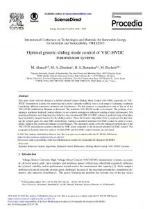
Applied MTdc test network
III. SIMULATION STUDIES In order to show the behavior of the proposed MTdc model, the test network shown in Fig. 8 was implemented in PSS®E. It consists of two offshore WPPs each aggregately represented by a full-converter wind turbine generator, two onshore power systems with local loads, and a MTdc network with in total 5 VSC terminals, with power ratings of 500 MVA for the WPVSCs and 350 MVA for the GSVSCs. One of the two onshore networks contains a local 500 MVA-rated generator to represent the local system oscillations. The direct voltage droop method has been employed to regulate the power distribution along the MTdc network [12]. First, the test system will be subject to artificial (ramped) wind speed variations, of which the results are shown in Fig.9. At 1 s, both wind parks decrease their power production at a rate of 100 MW/s, The current flowing into MTdc grid immediately decreases, which leads to a drop in the direct voltage in all the nodes. The GSVSCs respond instantly and decrease their active power output. The opposite happens when WPP 2 increases its power production back to 500 MW at 3 s, The higher power injection of WPVSC 2, leads to an increase in the direct voltages and consequently to an increased active power output of the GSVSCs. These variations initially lead to power unbalances in the onshore network, which can be noticed by the small rotor speed oscillations. Secondly a 250 ms-long three-phase fault is initiated at bus 5, with the simulation results shown in Fig. 10. It can be seen that the fault leads to an instant drop in the active power delivered by GSVSC5 while the WPVSCs continue delivering the same amount of wind power into the
6
Fig. 9.
Dynamic behavior of the system following wind power variations.
MTdc grid. The GSVSCs in the other synchronous system try to compensate by increasing active power but hit their overcurrent limits, Because of this, the direct voltage suddenly increases, which triggers the chopper-controlled braking resistors. After fault clearance at 2.25 s, the system oscillates to its pre-fault state. The generator oscillations show that with the applied dc grid control strategy, faults in one ac grid are conveyed to other asynchronous areas by the VSC-MTdc scheme. This interaction is relatively weak in the applied case but may be more severe depending on the network characteristics. Using more advanced MTdc control schemes (e.g. damping control) can minimize this issue. IV. CONCLUSION It is likely that future transmission systems will contain more VSC-HVdc links or even VSC-MTdc schemes to enable trade and offshore wind connections. The effects of such schemes on system transient-stability are yet to be determined. This calls for careful consideration of their modeling in stability software. These traditional simulation tools have no inherent way of modeling dc systems. This paper described a state-space representation of arbitrary VSC-MTdc systems for transient stability studies. Starting from topological information and cable electrical parameters for submarine cables, the creation of the relevant state space vectors and matrices were described, as well as their initialization by sequential load flow for ac/dc grids. An averaged VSC model using quasi steady-state phasors on the ac-side and elecro-magnetic transients on the dc-side has been used to couple the VSC-MTdc grid to the stability simulation. The described modeling framework was implemented into PSS®E by its user-defined modeling capabilities and Python scripting. Tests were performed on an exemplary network which showed plausible interactions between the VSC-MTdc system and the connected ac systems. Future work will focus on computation speed enhancements, dc power dispatching control strategies, and VSC participation in power system oscillation damping.
Fig. 10. Dynamic behavior of the system following a short circuit at bus 5.
REFERENCES [1]
“Pure Power: Wind energy targets for 2020 and 2030,” European Wind Energy Association, Tech. Rep., 2009. [Online]. Available: http://www.ewea.org [2] Siemens, PSS®E 32.0.5, “Program Application Guide, Volume II”, Oct. 2010 [3] P. Vormedal “Voltage Source Converter Technology for Offshore Grids” M.Sc. thesis, Dept. Elect. Power Engineering, Norwegian University of Science and Technology, Jun 2010 [4] C. Ismunandar, A. A. van der Meer, R. L. Hendriks, M. Gibescu, and W. L. Kling, “Control of multi-terminal VSC-HVDC for wind power integration using the voltage-margin method,” in Proc. 9th International workshop on Large Scale Integration of Wind Power into Power Systems as well as on Transmission Networks for Offshore Wind Power Plants, Québec City, Canada, Oct. 18–19, 2010, pp. 427–434 [5] V. Blasko and V. Kaura, “A new mathematical model and control of a three-phase AC-DC voltage source converter,” IEEE Transactions on Power Electronics, vol. 12, no. 1, pp. 116–123, 1997. [6] L. Harnefors, “Control of VSC-HVDC Transmission,” tutorial presented at the IEEE Power Electronics Specialists Conference, Rhodos, Greece, Jun. 15–19 2008. [7] Cuiqing Du, Agneholm E., “Investigation of Frequency/AC voltage Control for Inverter Station of VSC-HVDC”, IEEE 32nd Annual Conference on Industrial Electronics, Paris, 2006, pp. 1810-1815. [8] A. A. van der Meer, R. L. Hendriks, and W. L. Kling, “A survey of fast power reduction methods for VSC connected wind power plants consisting of different turbine types,” in EPE wind energy chapter 2nd seminar, Stockholm, Sweden, Apr. 23–24, 2009 [9] A. A van der Meer, R. L Hendriks, W. L. Kling, “Combined Stability and Electro-Magnetic Transients Simulation of Offshore Wind Power Connected through Multi-Terminal VSC-HVDC”, in Proc. IEEE Power and Energy Society General Meeting, Minneapolis, MN, Jul 19–24, 2010 [10] F. H. Branin, JR., “Computer Methods of Network Analysis,” Proceeding of the IEEE, vol. 55, no. 11, Nov. 1967, pp. 1787-1801 [11] J. Beerten, S. Cole, R. Belmans, “A Sequential AC/DC Power Flow Algorithm for Networks Containing Multi-terminal VSC HVDC Systems”, inProc IEEE Power and Energy Society General Meeting, Minneapolis, MN, Jul 19–24, 2010 [12] C.D. Barker, R Whitehouse, "Autonomous converter control in a multiterminal HVDC system", inProc. 9th IET International Conference on AC and DC Power Transmission, vol., no., pp.1-5, 19-21 Oct, 2010