Generating Synthetic Meta-data for Georeferenced Video Management Sakire Arslan Ay
Seon Ho Kim
Roger Zimmermann
Department of Computer Science University of Southern California Los Angeles, CA 90089
Integrated Media Systems Center University of Southern California Los Angeles, CA 90089
School of Computing National University of Singapore Singapore 117417
[email protected]
[email protected]
ABSTRACT Recently various sensors, such as GPS and compass devices, can be cost-effectively manufactured and this allows their deployment in conjunction with mobile video cameras. Hence, recorded clips can automatically be annotated with geospatial information and the resulting georeferenced videos may be used in various Geographic Information System (GIS) applications. However, the research community is lacking large-scale and realistic test datasets of such sensor-fused information to evaluate their techniques since collecting realworld test data requires considerable time and effort. To fill this void, we propose an approach for generating synthetic video meta-data with realistic geospatial properties for mobile video management research. We highlight the essential aspects of the georeferenced video meta-data and present an approach to simulate the behavioral patterns of mobile cameras in the synthetic data. The data generation process can be customized through user parameters for a variety of GIS applications that use mobile videos. We demonstrate the feasibility and applicability of the proposed approach by providing comparisons with real-world data.
Categories and Subject Descriptors H.2.8 [Database Management]: Database Application— Spatial databases and GIS ; H.3.4 [Information Storage and Retrieval]: Systems and Software—Performance evaluation (efficiency and effectiveness)
[email protected]
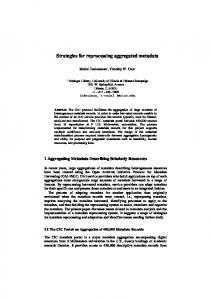
sensors (e.g., GPS and compass units) on mobile platforms such as handheld devices or vehicles of various forms. As a result, videos have gained mobility and attained geospatial properties through the association with sensor meta-data. This raises many interesting research challenges for the Geographic Information Systems (GIS) community. As an example, recently smartphones have become extremely popular in capturing and sharing videos. Because of the affordability of these camera-equipped gadgets, the general public is now generating and disseminating an extensive amount of video clips. The scenes captured in a video change with the movement and rotation of the camera. Figure 1 exemplifies the scene coverage of a video on a map, based on the associated GPS and compass sensor values. These geographically described (i.e., georeferenced) video data contain significant information about the region where they were captured and can be effectively utilized in various GIS applications to, for example, visually navigate and query the geo-space [11]. Potential mobile video applications are not limited to smartphones. Recently, some service vehicles such as city buses, ambulances, and police cars have been equipped with cameras for various reasons, e.g., to monitor the quality of service provided. These cameras record a vast amount of data that cover large geographic areas. It is often desirable to browse, summarize and search these videos to find the video sections that capture a particular region or a certain location.
General Terms Algorithms, Experimentation, Performance
Keywords GIS, georeferenced video, meta-data generation
1. INTRODUCTION Technological trends have enabled the cost- and energyefficient deployment of video cameras together with other Permission to make digital or hard copies of all or part of this work for personal or classroom use is granted without fee provided that copies are not made or distributed for profit or commercial advantage and that copies bear this notice and the full citation on the first page. To copy otherwise, to republish, to post on servers or to redistribute to lists, requires prior specific permission and/or a fee. GIS’10, 03-NOV-2010, San Jose CA, USA c 2010 ACM 978-1-4503-0428-3/10/11 ...$10.00. Copyright °
Figure 1: Map visualization of video scene coverage. The usage of georeferenced video meta-data has received special attention by researchers in the multimedia community. Such meta-data provide contextual descriptions of videos
at a semantically interesting level and enable effective and efficient management of mobile videos. For example, there have been studies on organizing and browsing images and videos according to their locations [15, 12, 5]. Some of these techniques are evaluated using the georeferenced images from popular image sharing services such as Flickr [12]. These community-contributed datasets are mostly based on user-provided geo-tags, therefore they may be subjective and ambiguous. Furthermore, each image/video is associated with only a single geographical location, which may not be sufficient for mobile videos. In our earlier work [1, 2] we proposed the use of geographical properties of video scenes as an effective means to aid in the search of large video archives. Subsequently, we introduced a camera prototype to capture videos along with location and direction meta-data, automatically annotated from sensors [1]. We collected many hours of georeferenced videos using our recording system for the evaluation of our mobile video management techniques. Other studies have generated their own georeferenced metadata [10, 9, 5]. Such real-world datasets are essential for the evaluation and comparison of various mobile video management techniques. However, the limitation of these datasets is that they were all generated within a controlled environment, therefore the behavior of the video capture can be perceived as subjective. Moreover, due to a highly labor intensive collection process, the amount of georeferenced real-world video data available has not been large enough to evaluate realistic application scenarios. To enable comprehensive performance evaluations on a large scale, much bigger datasets are required. Consequently, one important and urgent requirement to facilitate future research activities is the availability of well-described georeferenced video meta-data, enabling a systematic and extensive comparison of mobile video management techniques. However, collecting real-world data requires a considerable amount of time and effort. While there is a need for a collaborative effort to build a large repository of georeferenced videos, a complementary solution to fulfill the urgent requirement of the research community is to synthetically generate georeferenced video meta-data. In this paper, we propose an approach for generating synthetic video meta-data with realistic geographical properties for mobile video management research. We provide our observations about the behavior of mobile cameras and how to emulate such behavior when generating synthetic data. Note that the generated meta-data is based on the definition of our viewable scene model [1] that is comprised of a camera’s position in conjunction with its viewing direction, viewable distance and zoom level. Users can control the behavior of the proposed generator using various input parameters. Our contributions in this work include: • Identification and classification of the requirements on generating synthetic georeferenced video meta-data. • Design of algorithms to synthetically generate practical video meta-data with requested geospatial properties. In particular, the generation of video meta-data with realistic camera movements and camera rotations. • Customization of the generation process based on user parameters for broader applications. • Comparison and evaluation of the characteristics of the real-world and synthetic video meta-data. The rest of the paper is organized as follows. Section 2 contains a brief summary of the main concepts related to
georeferenced mobile video management. The requirements for generating synthetic video meta-data are discussed in Section 3. This is followed by the detailed description of the synthetic data generation process in Section 4. Section 5 presents the results of the comparison of the real-world and synthetic datasets. Section 6 provides a survey of related work. Finally, Section 7 concludes the study and discusses open issues.
2. 2.1
BACKGROUND Georeferenced Video Annotations
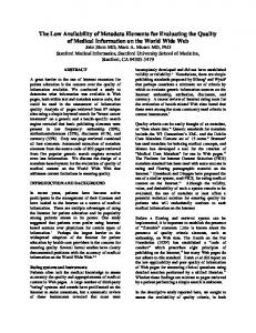
We define the scene that a camera captures as its viewable scene. In the field of computer graphics, this area is referred to as camera field-of-view (FOV). We describe a camera’s viewable scene in 2D space using the following four parameters: 1) the camera position P consisting of the hlatitude, longitudei coordinate read from a positioning device (e.g., GPS), 2) the camera direction vector d~ which is obtained from the orientation angle provided by a digital compass, 3) the camera viewable angle θ which describes the angular extent of the scene imaged by the camera [7], and 4) the visibility range R which is the maximum distance from the camera at which a large object within the camera’s field-ofview can be recognized. Then the camera viewable scene at ~ θ, R). In time t is denoted by the tuple F OV Scene(t, P, d, 2D space, the viewable scene of the camera forms a pie-sliceshaped area as illustrated in Figure 2a. Figure 2b shows an example camera F OV Scene volume in 3D space. For a 3D representation of F OV Scene, we would need the altitude of the camera location point (from the GPS device) and the pitch and roll values (from the compass) to describe the camera heading on the zx and zy planes (i.e., whether the camera is directed upwards or downwards). In this study we will represent the FOVScene in 2D space only. However, the data generator could be extended to 3D.
Figure 2: Illustration of FOVScene model (a) in 2D and (b) in 3D. The viewable scene of a camera changes as it moves or changes its orientation in the geo-space. In order to keep track of the FOVScenes of a moving camera over time, we ~ viewable anneed to record its location (P ), direction (d), gle θ, and visibility range R with a certain frequency. P and d~ values are periodically acquired from sensor devices. θ depends on the lens/image sensor combination used in the camera [8]. R can be obtained based on the equation R = f h/y, where f is the focal length, y is the size of the camera image sensor, and h is the height of the target object that will be fully captured within a frame. With regard to the visibility of an object from the current camera position, the size of the object also affects the maximum camera-toobject viewing distance. For large objects the visibility distance will be long whereas for small objects it will be short.
According to the required level of details in the videos, an appropriate R value can be used. In large scale applications, there may be thousands of moving cameras with different sensing capabilities. Each camera will record its FOVScene with a different sampling frequency. Intuitively, there should be a separate FOVScene quintuple for every video frame. According to the required granularity of the video meta-data, an appropriate sampling frequency can be determined by the user. Note that a higher sampling rate creates more detailed video scene descriptions, but requires a larger storage space. The assigned sampling rate should balance this tradeoff. Further details on timing and sampling frequency of the meta-data can be found in our earlier work [1].
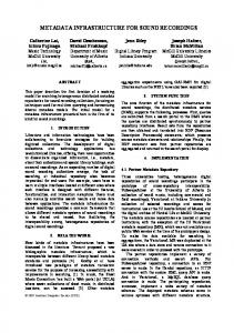
2.2 Real-world Video Collection To collect georeferenced video data, we have constructed a prototype system which includes a camera, a 3D compass and a GPS receiver. We used the JVC JY-HD10U camera which produces MPEG-2 HD video streams available in real time from the built-in FireWire (IEEE 1394) port with 30 frames per second data rate. To obtain the orientation of the camera, we employed the OS5000-US Solid State Tilt Compensated 3 Axis Digital Compass, which provides precise tilt compensated headings with roll and pitch data. To acquire the camera location, the Pharos iGPS-500 GPS receiver has been used. A program was developed to acquire, process, and record the georeferences along with the MPEG2 HD video streams. The system can process MPEG-2 video in real-time (without decoding the stream) and each video frame can be associated with its viewable scene information. More details on synchronization of meta-data with video content have been provided in our earlier work [1]. Figure 3a shows the setup for our recording prototype. We OceanServer OS5000-US Compass JVC JY-HD10U camera Pharos iGPS-500 Receiver
(a) (b) Figure 3: Experimental prototype systems to acquire georeferenced video. have mounted the recording system setup on a pickup truck and captured video outdoors in Moscow, Idaho, travelling at different speeds. For the real-world dataset (RW ) the average camera movement speed was around 27 km/h (≈ 17 mph), and the average camera rotation was around 12 degrees/sec. One meta-data tuple was generated every second, ~ θ, R) per 30 frames of video. We i.e., one F OV Scene(t, P, d, collected a total of 170 minutes (≈ 3 hours) of video data that covered a 6 km by 5 km region quite uniformly. The dataset contained 10,652 FOVScene tuples and its total size was approximately 23 MB. In order to evaluate the performance of several research techniques regarding georeferenced videos, much larger datasets are needed. However, collecting real-world data requires considerable time and effort, even for small datasets.
We also implemented a prototype georeferenced video acquisition module on a smartphone, an Apple iPhone 3GS handset, which provides the necessary built-in GPS receiver and compass functionality (see Figure 3b). We plan to collect more real-world data with this platform for further studies in the future.
3.
SYNTHETIC VIDEO META-DATA GENERATION REQUIREMENTS
We next review the requirements for the generation of georeferenced video meta-data. We specifically investigate the behavior of mobile cameras and how to simulate such behaviors in the synthetic data. Our goal is not to provide a case study generator that fulfills the requirements of a certain specific application. Instead, we present a customizable system which the user can configure according to the required meta-data properties for more general applications. The highlighted requirements are based on our analysis on the collected real-world data. Property Trajectory → pattern Rotation → pattern Visual → angle Visibility → range
Description Type of the trajectory that the camera follows Property that describes the behavior of the camera rotation. The visual angle for the camera field-of-view. The visible distance at which a large object within the camera’s field-of-view can still be recognized.
Table 1: Summary of camera template specification. In an actual video capture, the behavior of a camera (i.e., its movements and rotations) depends on the occasion and purpose of the video recording. Such camera behavior can be described by the pattern of movements and rotations, which we refer to as a camera template in this paper. A camera template overview is given in Table 1. In the template definition, the trajectory pattern property identifies the movement pattern of the camera trajectory. Example patterns include, network-based when a camera moves along a predefined network such as roads, free movement when a camera has no restriction in moving directions, or a combination of the two. The rotational behavior is described by the rotation pattern property. If the camera rotation is not allowed, this property is set to fixed and if the camera can be freely rotated (e.g., by a human user), this property is set to random. The visual angle and visibility range correspond to the parameters θ and R in the scene model, respectively. For a particular camera, we assume that all the georeferenced meta-data streams will have identical θ and R values. Consequently, in generating synthetic metadata, the generator produces meta-data only for the camera trajectory and rotation. Table 2 provides the detailed list of the camera template parameters, their grouping and also their corresponding notations. Below we provide three typical example templates for mobile videos: 1. Vehicle camera. The camera is mounted on a vehicle and moves along road networks. Examples include cameras equipped on city buses, police cars or ambulances. The trajectory pattern is network-based. The movement speed is assumed mostly fast and steady.
Trajectory pattern
Visual angle
1) T network θ road [ ],P ,t ,n,p,A) (Vm e s walk ,U ) 2) Tf ree (Vm 3) Tmixed walk ,P ,t ,D (Vm e s rand ,Nrand ) road [ ] Vm walk Vm Pe ts n, p
A U Drand , Nrand offset ωmax αmax
Visibility range R
Rotation pattern
1) fixed 2) random (offset,ωmax ,αmax )
Array of speed limits (in km/h) for different road types on the road network. Maximum walking speed (in km/h). The probability of having a stop event. The duration of stop event (in s). Parameters for Binomial distribution. Used in modeling the camera deceleration. Camera acceleration rate (in m/s2 ). Distribution of initial camera locations. Distribution and percentage of the random movement sections in Tmixed . The angle offset (in degrees) with respect to the moving direction. The maximum allowed rotation per time unit (in degrees/s). Maximum allowed rotation (in degrees) with respect to offset (i.e., the camera direction is limited within offset∓αmax angle range).
Table 2: Details of camera template parameters.
3.1 Camera Movement Requirements For the camera templates described above, there are three major behavioral patterns (i.e., trajectory patterns) for the camera movement: 1. Tnetwork : Moving on a given road network. 2. Tf ree : Moving on an unrestricted path. 3. Tmixed : Partly following a network and partly moving on a random path. In order to realistically simulate the movements, some other practical properties are required in addition to the trajecroad walk tory patterns, such as: 1) maximum speed (Vm [ ],Vm ),
3.2
Camera Rotation Requirements
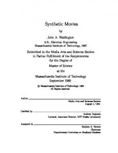
There can be certain restrictions for a practical simulation of rotational behaviors, even for freely rotating camera directions. These restrictions are required to be enforced by assigning appropriate values to certain camera template parameters (see Table 2). For example, offset parameter defines the initial bearing of the camera. If the camera direction is fixed then the camera direction will be analogous to the moving direction, maintaining the angle offset with respect to the moving direction. Often, to ensure visual quality in captured videos, the rotation speed is limited within a certain threshold. ωmax parameter defines the maximum allowable rotation per time unit. For the random rotation pattern, the user might want to restrict the maximum rotation with respect to the offset. The αmax parameter defines the maximum allowed rotation around the offset. In collecting real world georeferenced meta-data, the camera location and direction values are acquired from two independent sensors. However, based on our analysis on the real data, we observed that the movement and rotation of a camera is correlated. For example, cameras mostly point towards the movement direction (with some varying offset). In addition, when the camera trajectory makes a turn at a corner or a curve, the camera direction also changes. For fast moving cameras (e.g., a camera mounted on a car) there is a close correlation between the movement speed and the amount of rotation. Such relationships are caused by human behavior in controlling the camera rotation. The faster the camera moves the less it rotates, mainly because human operators try to avoid fast horizontal paning such as to cautiously maintain the quality of videos. Figure 4 illustrates this observation based on the real world data. The average rotation of a camera linearly decreases as its movement speed increases. 18 16 14 12 10 8 6 4 2 0
Rotation (Real Data)
0-5 5-10 10-15 15-20 20-25 25-30 30-35 35-40 40-45 45-50 50-55 55-60
Camera Template
2) frequency and duration of stops (Pe , ts ), and 3) the camera acceleration and deceleration parameters (n, p, A), etc. Table 2 lists the required camera template parameters to configure the camera movements of the trajectory types. A mobile camera is an example of a moving object whose positions are samples at points in time. In the field of spatiotemporal databases, there exists an extensive collection of research for generating synthetic moving object test data for evaluating spatio-temporal access methods. We adopt and revise some well-known moving object data generation techniques for the proposed synthetic data generation. Details on generation of camera movements will be described in Section 4.1.
Average Rotation
The camera heading with respect to the direction of vehicle movement is fixed (i.e., the rotation pattern is fixed ). Thus, the camera direction changes only when the vehicle makes turns. 2. Passenger camera. A passenger traveling in a vehicle operates the camera. Examples include hand-held cameras used to capture scenery, buildings, landmarks, etc. The camera trajectory pattern is set to networkbased. The camera bearing changes when the moving direction changes and when the user rotates the camera, i.e., the rotation pattern is specified as random. 3. Pedestrian camera. A walking pedestrian holds the camera. Examples include hand-held cameras used to capture tourist attractions, landmarks, and special events. The camera mostly follows a random trajectory, analogous to a walking path. However, it might also follow a predefined network, such as sidewalks or hiking trails. The trajectory pattern is a combination of network-based and free movement. The camera can be rotated freely, therefore the rotation pattern is set to random.
Speed (km/h) Figure 4: Analysis of real-world data: average rotation as a function of the camera speed.
The aforementioned properties surely cannot consider all possible aspects of mobile video recording. The characteristics of georeferenced video data may widely vary depending on when, where, by whom and for what purpose the video is captured. Users may want to create and customize new camera templates by defining different movement and rotation specifications. Hence, a synthetic data generator needs to be able to fulfill these requirements. By giving users the flexibility to customize the camera behavior, our data generator can provide synthetic data applicable to a wide range of application scenarios.
4. VIDEO META-DATA GENERATION
Figure 5: Generator architecture. Our methodology for generating synthetic georeferenced meta-data is based on the observations stated in Section 3. We generate the synthetic data in two major steps (see Figure 5): First we create camera movement trajectories, and then in the second step we estimate the camera direction for each location on the movement path.
4.1 Generating Camera Movement To create the camera trajectories, we adopted two widely accepted spatio-temporal data generators for moving objects: the Brinkhoff generator [3] and the GSTD generator [13]. The former is used to generate the trajectories of a camera that moves on a road network (Tnetwork ), while the later is used to simulate the trajectories of a pedestrian (Tf ree ). The basic behaviors of the generators are controlled by a set of parameters, however, more sophisticated additional changes for the georeferenced video management research required additional considerations. In order to ensure that the generated camera trajectories from the Brinkhoff and GSTD algorithms had the required specifications, we modified both software algorithms and added some features.
4.1.1
Network-based Camera Movement (Tnetwork ) We generate network-based trajectories using the Brinkhoff road algorithm with the required maximum speed (Vm [ ]), given road [ ] defines the maxia camera template. The array Vm mum allowed speeds for traveling on freeways, main roads and side roads. The Brinkhoff generator adjusts the speed of a moving object based on the maximum speed allowed on the current edge (i.e., road) as well as the load on that edge (the current number of objects using it). The Brinkhoff generator uses TIGER/Line files [17] to build the road network. The routes that the moving objects follow are determined by selecting the best network edges between the starting and destination points. The objects always try to move at the
maximum possible speed and their movement is continuous unless there is congestion on the current edge. The Brinkhoff algorithm does not introduce any stops at intersections (e.g., at traffic lights and stop signs). In addition, there is no support for modeling the acceleration and deceleration of the objects. Thus, we modified the original algorithm and inserted stops and decelerations at some road crossings and transitions. The probability of having a stop event at an intersection is given by Pe . In a deceleration event, at every time unit the cameras’ current speed υ is reduced to υ × B(n, p)/n where B(n, p) is a binomially distributed random variable (n is the number of experiments and p is the probability for a positive outcome). In a typical run, we use n = 20 and p = 0.5, which results in a 50% speed reduction at each time unit [4]. In a stop event, the camera decelerates and reduces its speed to 0 km/h. After a full stop, it stays steady for a duration of ts seconds. The acceleration event occurs when the available speed limit on the current edge increases or when the camera starts to move after a stop event. The cameras accelerate with a constant acceleration road rate of A m/s2 [4]. All Vm [ ], Pe , ts , n, p, and A values are obtained from the camera template definition. The output for the Tnetwork trajectories includes the timestamped camera location updates with a sampling rate of fsample . It generates N trajectories with a maximum trajectory length of L. N and L values are input parameters to the generator.
4.1.2
Unconstrained Camera Movement (Tf ree ) We use the GSTD algorithm to generate the camera trajectories with unconstrained movement. GSTD was one of the first generators for creating moving object data. The behavior of movements can be customized by adjusting the domain of displacements ∆c[ ], i.e., the minimum and maximum possible movements on the x and y axes. The object movement can either be random or partly restricted on one axis (i.e., the objects are forced to move towards a particular direction). To ensure a certain speed level for the camera trajectories, we modified the algorithm and added a speed control mechanism. The user provides the desired maximum walk speed (Vm in km/h) in the camera template specification. Then, the generator calculates the object speed for every location point on the trajectory and ensures that overall, the user speed requirements are fulfilled. To simulate the movement of a pedestrian, the maximum walking speed is set to 5.43 km/h. The initial locations of the cameras are calculated based on the distribution function U , which is given in the camera template. It is important to note that GSTD represents object locations as relative distances with respect to the mid-point of the region. However, our georeferenced video model [1] requires the location meta-data in the geographic coordinate system (i.e., as latitude/longitude coordinates). Therefore, we also modified the trajectory representation of GSTD and generated object movements with latitude/longitude coordinates. Such a representation enables the monitoring of the object speed given that the speed requirements are defined in common metric units (i.e., km/h). In addition, unlike the original GSTD algorithm, we report location updates in the trajectory periodically with a parameterized sampling rate (fsample ). 4.1.3
Mixed Camera Movement (Tmixed ) The trajectories in this category are combinations of subtrajectories from Tnetwork and Tf ree . Cameras sometimes
follow the network and sometimes move randomly on an unconstrained path. Algorithm 1 formalizes the trajectory generation of Tmixed . We first generate a Tnetwork trajectory (line 2), then we randomly select n point pairs S = {hpi,1 , pi,2 i, (1 ≤ i ≤ n)} on the trajectory, where each point pair Si represents a segment on the trajectory. The duration of each segment (|Si |) can change between 0 and |Tinit |/4, where |Tinit | is the length of the original Tnetwork trajectory. Function GetLineSegments() randomly ¡P n ¢selects n subsegments in Tinit , such that Nrand = /|Tinit |. S i i=1 Recall that, Nrand is the camera template argument that specifies the percentage of random movement in the generated Tmixed . The distribution of the segments on the trajectory is given by the camera template argument Drand . It can be either uniform, Gaussian (around the middle), or skewed (towards the beginning or end of the trajectory). Each of these segments (S(i)) is removed from the trajectory and replaced by a new sub-trajectory Trand (i) with random movement that starts at pi,1 and ends at pi,2 (lines47). The function CreateRandTraj() implements a restricted version of GSTD, where the starting and end points are predefined. Note that if pi,1 = pi,2 , nothing is removed. One important issue in creating a Tmixed trajectory was merging the trajectories from Tnetwork and Tf ree together. We made sure that the trajectories from both groups have the same output format. Also, it is not necessarily true that the removed and inserted segments are of equal time length (i.e., |S(i)| = |Trand (i)|). Therefore, there might be overlaps and/or gaps in the timestamps of the combined trajectories. Algorithm 1 revises the timestamps in Tmixed (function AdjustTimestamps()) and makes sure that the timing within the final trajectory is consistent. Algorithm 1 MixedMovement(netT arg,randT arg,CAM ) 1 CAM ← camera template specification, netT arg ← arguments for creating Tnetwork , randT arg ← arguments for creating Tf ree . Returns: Tmixed trajectory. 2 Tinit = CreateNetTraj(netT arg,CAM ) {Generate a Tnetwork trajectory} 3 S[ ] = GetLineSegments(|Tinit |,CAM ); 4 for all S(i) = hpi,1 , pi,2 i, (1 ≤ i ≤ n) do 5 Trand (i) = CreateRandTraj(randT arg, pi,1 , pi,2 ); {Create a Tf ree trajectory starting at pi,1 and ending at pi,2 } 6 Tmixed = Tinit .Replace(pi,1 , pi,2 ,Trand (i)); 7 end for 8 return AdjustTimestamps(Tmixed );
4.2 Generating Camera Rotation An important difference between the traditional moving object data generators and our work is the computation of the camera direction. Assigning meaningful camera direction angles for the location points along the trajectory is one of the novel features of the proposed data generator. The assignment of direction angles is customized following the specifications provided by users (see Table 2).
4.2.1
Generating Camera Direction Angles
As shown in Figure 5, after the generator creates the camera trajectories, it assigns appropriate direction angles for all sampled points on the trajectories. Algorithm 2 formalizes the assignment of camera directions. The camera movement trajectory Tk and camera template specification CAM are given to the algorithm as input. First, the algorithm assigns the camera direction to be the moving direction and stores
the camera trajectory with moving directions in array Mk . Next, it adjusts the rotations that exceed the CAM.ωmax threshold (lines 3-6). If the camera can be freely rotated (i.e., random rotation), the algorithm assigns an appropriate random direction angle for each point in Mk (function RandomizeDirections()). The amount of rotation is computed with regard to the current camera speed and the specifications defined in CAM. Algorithm 2 Mk = AssignDirections(Tk ,CAM ) 1 Tk ← The trajectory array for Vk , CAM ← Camera template specification. Returns: Mk ← The meta-data array for Vk . 2 Copy Tk to Mk ; {Initially set the direction for each data point to ”moving direction+CAM.offset” } 3 for i = 1 to | Tk | do 4 Tk (i).dir = GetMovingDirection(Tk ,i,CAM ); 5 end for; 6 AdjustRotations(Mk ,CAM ); 7 if CAM.rotation pattern is “random” then 8 RandomizeDirections(Mk ,CAM ); 9 end if 10 return Mk ;
4.2.2
Calculating Moving Direction
The moving direction of the camera is estimated as the direction vector between two consecutive trajectory points. Given a camera trajectory Tk , the moving direction at sam−−−−−−−−→ − ple point t is given by the unit vector, → m = Tk (t-1)Tk (t). The camera direction angle (with respect to North) at sample point t can be obtained by: → − m .y ) + offset Tk (t).dir = cos−1 ( → |− m| In Algorithm 2, the function GetMovingDirection() calculates the moving direction angle at all trajectory points and initializes the camera direction to the moving direction plus the given offset (CAM.offset). Next, the function AdjustRotations() checks whether the rotations due to the changes in the moving direction are below the required threshold CAM.ωmax . The synthetically generated camera trajectories often have sharp turns which results in abrupt rotations in the camera moving direction, which is unusual in reality. Our observation on real-world data shows that the change in the moving direction is much smoother. As an example, for vehicle and passenger cameras, when the vehicles turn at corners and steep curves on the road network, the moving direction will gradually change and it will take several seconds to complete the turn. Figure 6a shows an example trajectory from the real data where the car makes a left turn. The change in the speed is illustrated with different color codes, i.e., red points mark the slowest and blue points the fastest speeds. The arrows show the moving directions. Figure 6b illustrates a trajectory synthetically generated for the same road intersection. When the point moving direction is estimated from the movement vector, the rotation angle within a single time unit can be as large as the right angle (the rotation at the corner point ≥ 90o in Figure 6b). In order to simulate the direction change during a turn, the generator distributes the total rotation amount among several trajectory points before and after the corner point. As seen in Figure 6c, with this method the moving direction changes gradually, and the rotation between two consecutive points is guaranteed to be under CAM.ωmax . The camera locations are also updated based on the adjusted moving directions.
(a)
(b)
(c)
Figure 6: Illustration of camera direction adjustment for vehicle cameras. (a) Real-world data, (b) synthetic data before direction adjustment, and (c) synthetic data after direction adjustment. The function AdjustRotations() in Algorithm 2 checks for the rotation angle at each sample point, and smoothes the sharp turns by interpolating the rotation angle among several neighboring sample points. Algorithm 3 formalizes the adjustment of rotations. The meta-data array Mk with moving directions is given to the algorithm as input. The algorithm checks the rotation amounts between all consecutive trajectory points in Mk . If the rotation amount exceeds CAM.ωmax at point Mk (i), then the algorithm scans the trajectory backwards and forwards until it finds two trajectory points Mk (i-∆bwd ) and Mk (i+∆f wd ) such that the camera can be safely rotated from Mk (i-∆bwd ) to Mk (i+∆f wd ) without violating the CAM requirements. When such points are found the directions between points Mk (i-∆bwd ) and Mk (i+∆f wd ) are interpolated (line 18). Given a sample point j, function InterpolateAngle() returns the j th interpolated angle, i.e., ¶ µ Mk (i + ∆f wd ).dir − Mk (i − ∆bwd ).dir Mk (i−∆bwd ).dir+j ∆bwd + ∆f wd It guarantees that the returned direction is between CAM.offsetCAM.αmax and CAM.offset+CAM.αmax . Algorithm 3 AdjustRotations(Mk ,CAM ) 1 Mk ← The meta-data array for Vk , CAM ← Camera template specification. Returns: Mk with revised directions. 2 for i = 2 to | Mk | do 3 {If the difference between two consecutive angles is greater than CAM.ωmax } 4 if AngleDiff(Mk (i).dir, Mk (i − 1).dir) > CAM.ωmax then 5 ∆f wd = 1; ∆bwd = 0; {Scan backwards and forwards to find two data points such that the rotation between them is possible without exceeding CAM.ωmax } 6 repeat 7 dir change=AngleDiff(Mk (i+∆f wd ).dir,Mk (i-∆bwd ).dir) 8 if ∆f wd > ∆bwd then 9 increase(∆bwd ); 10 else 11 increase(∆f wd ) 12 end if 13 until (dir change ≤ ωmax * (∆f wd +∆bwd )); 14 {Adjust all directions between (i-∆bwd ) and (i+∆f wd ) such that rotation amount do not exceed CAM.ωmax and CAM.offset∓αmax } 15 for j= i-∆bwd to (i+∆f wd ) do 16 Mk (i).dir=InterpolateAngle(j,Mk (i-∆bwd ).dir, Mk (i+∆f wd ).dir, CAM.ωmax , CAM.αmax ) 17 end for 18 end if 19 end for 20 return Mk ;
4.2.3
Assigning Random Direction Angles
In Algorithm 2, if the camera’s bearing with respect to its moving direction is fixed, the function returns the meta-data
array with adjusted moving directions. However, if the camera rotation is allowed, then the algorithm randomly rotates the directions at each sample point towards left or right. Given the initial camera directions based on the moving direction, function RandomizeDirections() updates direction angles to simulate the rotation of the camera by a user. Algorithm 4 details the randomization of the directions. It generates a random rotation amount which is inversely proportional to the current speed level (line 4). The faster a camera moves the less rotation there will be. In addition, the algorithm makes sure that the rotation amount is less than CAM.ωmax and the assigned camera direction angles are between CAM.offset-CAM.αmax and CAM.offset+CAM.αmax (line 5). The algorithm returns the meta-data array with updated directions. Algorithm 4 RandomizeDirections(Mk ,CAM ) 1 Mk ← The meta-data array for Vk , CAM ← Camera template specification provided by user. Returns: Mk with revised directions. 2 for i = 2 to | Mk | do 3 repeat 4 rotate = (getRandNum()*getRandSign())÷Mk (i).speed; 5 until (Mk (i).dir +rotate ≤ CAM.ωmax ) and (CAM.αmax ≤ Mk (i).dir+rotate ≤ CAM.αmax ) 6 Mk (i).dir = Mk (i).dir + rotate; 7 return Mk ; 8 end for
4.3
Creating Meta-data Output
Our generator can either create the georeferenced metadata output in text format or directly insert the meta-data tuples into a MySQL database. The output is the list of ~ updates. the sampled camera location (P ) and direction (d) Following the input sampling rate (fsample ), each meta-data item is assigned a timestamp. For timestamps we use the Coordinated Universal Time (UTC) standard format. The first data point in a meta-data stream is assigned the current UTC time. The rest of the timestamps are adjusted according to the given granularity in time based on fsample .
5. 5.1
EXPERIMENTAL EVALUATION Comparison with Real-world Dataset
In this section we empirically examine some high-level properties of the synthetic georeferenced video meta-data. We analyze the movements and rotations of both the realworld and synthetic datasets. The effectiveness of the synthetic data generation approach is evaluated using a highlevel comparison between the real-world and synthetic data obtained for the same geographical region.
Datasets and Evaluation Methodology
Using the proposed georeferenced video meta-data generator, we produced two groups of synthetic data, namely Scar using the vehicle camera template and Spass using the passenger camera template. For each synthetic data group, we generated 10 datasets. For the first group (Scar ), the cameras cannot be rotated, therefore the camera orientation is the same as the moving direction. For the second group (Spass ) the camera can be rotated freely. Both synthetic data groups were created based on the road network of Moscow, Idaho, where the real-world data were collected. The maximum speed and object class parameters for both Scar and Spass were adjusted to make the maximum camera speed comparable to the real-world data. The average length of the video files (i.e., L) in the synthetic datasets was also similar to that of the real-world video files. The output sampling rate fsample was set to 1 sample/s. Table 3 summarizes the properties of the generated data. The values from the 10 datasets in each of the groups Scar and Spass were averaged and we only report these averaged values in Table 3. To evaluate the applicability of the synthetic datasets, we are interested to analyze the important characteristics of synthetic datasets and compare them to those of the realworld dataset (RW ). We compare Scar and Spass with RW in terms of, 1) the speed of the cameras and 2) the rotation of the cameras. We report the average and maximum values for speed and rotation, and the frequency distribution of the different speed and rotation levels within the datasets. Note that the properties of the real-world dataset is highly subjective and depends on how the user moves and rotates the camera. During real-world data collection, we rotated the camera as needed to capture important scenes and avoided fast movements and rotations.
Maximum Average StdDev of speed speed speed (km/h) (km/h) (km/h) Synthetic Data with Fixed Camera (Scar ) Synthetic Data with Free Camera Rotation (Spass ) Real-world Data (RW )
27.14
12.82
87.28
27.32
13.01
83.50
27.03
13.68
Table 4: Characteristics of the camera speed.
Comparison of Camera Movement Speed
First, we analyze how fast and how rapidly cameras move. When we generated Scar and Spass , we set the maximum alroad lowable speed parameter Vm [ ] based on the speed limits of the different types of roads in the region (i.e., 88 km/h for highways, 56 km/h for main roads, and 40 km/h for side roads). Recall that the generator calculates the maximum allowable speed on different edges of the road network based on this parameter. The other camera template parameter values are A = 12 m/s2 [4], Pe = 0.3, and ts = 3s. For all 10 datasets in Scar and Spass , we calculated the absolute speed of the camera at each trajectory point. Table 4 reports the maximum and average values and the standard deviation of the camera speed. The values are averaged for the 10 datasets in Scar and Spass . We observe that the average and standard deviation values for both Scar and Spass are very close to the values of RW . This implies that the point speed distributions of the synthetic and real-world datasets are quite similar. To further investigate this, we constructed the histogram for different speed ranges in Scar and RW . Figure 7 shows the percentages of the trajectory points for various speed ranges. While Scar and RW have similar trends, for Scar the majority of the trajectory points have speed values around the average speed, whereas for RW the distribution of the camera point speed is more uniform. In dataset Scar , cameras always try to travel at the maximum allowed speed. They only slow down or stop when they are required to do so by traffic lights, stop signs,
87.91
30
Synthetic Data (Scar)
Real Data
25 20 15 10 5 0 0-5 5-10 10-15 15-20 20-25 25-30 30-35 35-40 40-45 45-50 50-55 55-60
5.1.2
etc. The cameras always accelerate/decelerate with a certain rate. On the other hand, in RW cameras usually speed-up and slow down with a lower acceleration/deceleration rate resulting in smoother speed transitions. This is due to the fact that human operators were very cautious in driving a car during the real-time video capture. Note that the trend in the speed histogram might change for different real-world datasets. The average speed limit for the road network used in the data generation was around 40 km/h (≈ 25 mph). This explains the dense population of the trajectory points between speed levels 20-40 km/h. Figure 8 illustrates the camera trajectories of the real-world dataset and a sample synthetic dataset. The color highlights on the trajectories show how fast cameras are moving on the road network. The blue color indicates the fastest speed while the red color marks the slowest speed. Note that overall, the movement behaviors of the cameras in both datasets are similar.
Percentage of Trajectory Points (%)
5.1.1
Speed (km/h) Figure 7: Comparison of camera speed distributions for Scar and RW .
The camera movements of both the Scar and Spass datasets are based on road networks, therefore their trajectory generation is the same. We obtained similar results for the comparison of Spass with RW as we did for Scar and RW . We omit these results due to space considerations.
5.1.3
Comparison of Camera Rotation
Next, our objective is to examine the properties of the camera rotations in the synthetic datasets and analyze the practicality of the data generator by comparing the rotation characteristics of Scar and Spass with RW . We calculated the absolute rotation (in degrees/s) of the camera at each trajectory point for all 10 datasets in Scar and Spass . In Table 5, we report the maximum and average rotations as well as the standard deviation of rotations within each dataset. Again, the values were averaged for the 10 datasets in Scar and Spass . The maximum rotations obtained from Scar and Spass were limited by the rotation thresholds provided to the data generator as inputs (i.e., 30 and 60 degrees/s, respectively). For RW , the maximum rotation was relatively large. Although not frequent, there were a few fast rotations in the
Synthetic Data with Fixed Camera (Scar ) Synthetic Data with Free Camera Rotation (Spass ) Real-world Data (RW )
Number of video files 40 40 25
Total number of trajectory points 11849 11946 10170
Average video length (s) 299 300 426
Maximum speed (km/h) 87.91 87.28 83.50
Table 3: Properties of the synthetic and real-world datasets.
(a) (b) Figure 8: Illustration of camera movement speed on map. (a) Real world data RW , (b) synthetic data Scar . Maximum Average StdDev of rotation rotation rotation (degrees/s) (degrees/s) (degrees/s) Synthetic Data with Fixed Camera (Scar ) Synthetic Data with Free Camera Rotation (Spass ) Real-world Data (RW )
32.33
4.64
7.24
55.27
12.59
9.35
107.30
11.53
14.02
Table 5: Characteristics of the camera rotation. real-world data resulting in larger values for maximum and standard deviation measurements. For Scar , since the cameras mostly travel on straight roads, the average rotation is quite small (