strategy using spatial models of building parts and information fusion of aerial ... the domain specific information fusion and present results on a sub-urban.
Generation of 3D City Models using Domain-Specific Information Fusion Jens Behley and Volker Steinhage Institute of Computer Science III, Rheinische Friedrich-Wilhelms-Universit¨ at, 53117 Bonn, Germany
Abstract. In this contribution we present a building reconstruction strategy using spatial models of building parts and information fusion of aerial image, digital surface model and ground plans. The fusion of sensor data aims to derive reliably local building features and is therefore controlled in a domain specific way: ground plans indicate the approximate location of outer roof corners and the intersection of planes from the digital surface model yields the inner roof corners. Parameterized building parts are selected using these corners and afterwards combined to form complete three-dimensional building models. We focus here on the domain specific information fusion and present results on a sub-urban dataset.
1
Introduction
In the recent years three-dimensional city models became increasingly important in many applications. For instance, many manufacturers of navigation systems integrate the ability to visualize urban environments in a three-dimensional ego view. In this view, prominent buildings or landmarks are visualized to enable a more intuitive navigation. Besides this, Goggle Earth and other programs enable the user to view their environment from above and at many places even threedimensionally. Three-dimensional city models are also commonly used in the field of town-planning, pollution simulation and virtual tourism. The increasing demand for either simple or complex building models can’t be accommodated by solely manual reconstruction. Therefore automated reconstruction is an on-going research topic in the computer vision community. In this paper we propose a reconstruction process that employs the information fusion of aerial images with ground plans and aerial images with airborne laser scanning data to extract reliable local building features, i.e. roof corners, and a domain-specific building modelling [1]. The paper is organized as follows. First, we discuss related work in section 2. We briefly introduce the used sensor data and modelling by parameterized building parts in section 3. Then, we describe in section 4 our approach to reconstruct buildings using these parameterized building parts. Section 5 presents some implementation details. Section 6 presents our current results and finally section 7 concludes and suggests some improvements to further increase the automation.
2
Related work
Building reconstruction from images and other inputs is a classical application in computer vision. In the last decade several approaches have been presented to solve this problem by using aerial images [1, 2, 3, 4, 5]. Digital surface maps (DSM) were also used to reconstruct buildings [6, 7]. A more general overview on building reconstruction is given in [8, 9]. Using more than one source of information is advantageous, since inadequacies in one data source can be accommodated by another data source. Thus many research groups investigate the fusion of different data sources for reconstruction. To model buildings, several standard representations from computer graphics have been utilized, e.g. boundary representation or CSG. Also domainspecific representations have been developed. In the remainder of this section, we summerize the most relevant related work concerning information fusion and domain-specific modelling. Haala and Brenner [10] use ground plans and DSM to reconstruct buildings. Their approach uses the ground plans to extract rectangular regions to position CSG models. In the next step the parameters of the models are optimized to minimize the error in respect to the DSM. In contrast to [10] we use aerial image additionally, since the ground plans don’t resemble the observable roof outline neither topologically nor geometrically. Furthermore, we use the different sensor sources in a interwoven fashion. This means that information from one sensor source guides the feature extraction of another sensor source and vice versa. Fischer et al.[1] use parameterized building parts and multiple aerial images to reconstruct buildings. A tight coupling of two-dimensional and threedimensional features and aggregates enables a robust reconstruction. Starting with corners and edges, two dimensional corner observations are derived and via stereo reconstruction enriched to three-dimensional corner observations. These corner observations are used to select building parts, which are combined to complete three-dimensional building models. The major part of this process is adopted in this paper and the main points will be summarized in the next sections. In contrast to [1] we integrate different sensor sources to further improve the automated reconstruction. Lafarge et al. [7] also use parameterized building parts and a DSM to reconstruct buildings. First, a subdivision in two-dimensional support regions is performed. The support regions are used to position three-dimensional parameterized building parts. A Markov Chain Monte Carlo approach is used to determine the parameter settings of the building parts. However, the extraction of the precise roof outline is difficult due to the density of airborne laser scanning and can only be approximated. We tackle this problem by using a aerial image where the resolution is naturally much higher. Furthermore, our building modelling enforces geometrically correct reconstructions, which is not mandatory in the approach by Lafarge et al. How this geometrical correctness could be assured, will be one topic of the next section.
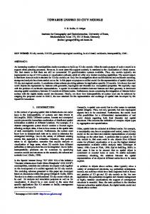
Fig. 1. Some building parts: flat, gable, mansard and hip roof terminal; gable roof X-connector, gable roof L-connector. Plug faces are drawn dashed. Note, that we distinguish between different types of plug faces, i.e. the mansard roof plug face is only connectable to the mansard roof terminal in this collection of building parts. However, the gable and hip roof are connectable, since they have the same type of plug face.
3
Sensor data and modelling approach
We use aerial imagery with a resolution of about 10 cm, while the digital surface model (DSM) generated from airborne laser scanning, shows a not regularized resolution of about 50 cm, i.e. the data points are not interpolated to a grid. The aerial images are so called orthophotos, which implies that a slight perspective distortion is visible and ground plan and DSM are slightly translated in respect to the observeable roofs in the aerial image. The building ground plans describe the building outline measured in the height of 1 m above the ground. All these data are referenced in the common Gauss-Kr¨ uger coordinate system and was kindly provided by the land register and surveying office of the city of Bonn. The modelling is based on typed and parameterized building parts (cf. [1]). The types correspond to different roof types and shapes of ground plans. Building parts must be connected(”plugged”) via typed plug faces and hence a topological and geometrical correctness can be assured. Some of the building parts, which we use, are shown in figure 1. Based on the number of plug faces (dashed lines in figure 1) building parts with one plug face will be called terminals, while building parts with more than one plug face will be called connectors. Building parts are encoded hierarchically by a boundary representation (cf. [11]). All faces and corners (vertices) are labeled with domain specific attributes; e.g. wall faces, roof faces, ridge corners, etc. Furthermore, edges are labeled with their orientation in respect to the ground plane, i.e. ’horizontal’, ’vertical’ and ’sloped’. We also classify normals of adjoining faces to the left and right side of an edge. The combination of corner, edge and face labels enables a robust so called indexing of building parts by matching of these labels [1]. We use symbolic parameters in the coordinates of the vertices to parameterize the building parts. When connecting two building parts the same parameters are unified, if they appear in the plug face, and renamed otherwise. This ensures consistent parameterization even in the connected building parts and in the final building hypothesis accordingly. The selection and combination of building parts into complete three-dimensional building models is described in the next section.
Feature Extraction by Information Fusion
Indexing
Planning
Verification
ground corners ground plan eaves corners aerial image ridge corners DSM
Fig. 2. Our reconstruction strategy and the data flow depicted by arrows. First, information fusion of aerial image, ground plan and DSM is used to derive eaves (green) and ridge corners (blue). These corner observations are used to index building parts. Next, the building parts are combined to complete building hypotheses by a planning procedure. Finally, the hypothesis that minimizes the error in respect to the DSM is selected as reconstruction result.
4
Reconstruction strategy
The following strategy is motivated by the underlying building model and the provided data. We can identify three classes of corners in the building model, namely eaves (outer roof corners), ridge (inner roof corners) and ground corners. These classes are extracted from the data in different ways. We therefore call our feature extraction domain-specific. Figure 2 highlights the main stages in our reconstruction process – feature extraction, indexing, planning and verification. First, we use the ground plan to extract the region of interest from the aerial image and DSM. Furthermore, we use the ground plan to infer the location of the eaves corners in the aerial image. However, wall corners in the ground plan have generally not the same location as the corresponding roof corners, due to overhanging roofs. But these roof corners are located in the proximity of the ground corners. Furthermore, not all wall corners correspond to roof corners at all because of convex and concave recesses by terraces, balconies etc (cf. figure 3). We account this fact by a shape generalization of the ground plan, which removes small sized border lines caused by terraces, balconies etc. The orientation of the remaining ground plan walls determine the orientation of eaves in the aerial image. Roof planes can be derived from the DSM using a plane segmentation. Intersecting these planes results in the inner three-dimensional roof edges. We determine the position of ridge corners using the intersections of this inner roof edges. Moreover, the intersections of horizontally inner roof edges with the ground plan induce another type of ridge corners, the ridge points of gable roofs, and their approximate (due to roof overhangs) location (cf. section 5). Ground corners can not be observed directly neither in the aerial image nor the DSM. In the current version of our approach we predict the location of ground corners by using the location of eaves corners.
Fig. 3. A L-shaped building with its ground plan. In the ground plan additional details occur, which are not observable in the roof outline. Also a displacement due to roof overhangs is visible. The middle picture shows results of the eaves corners (green) and ridge corners (blue) extracted by our feature extraction (see section 5). The picture on the right shows our reconstruction result.
In summary, the corner and edge features extracted from the ground plan as well as the three-dimensional planes, edge, and corner features derived from DSM determine their approximate locations in the aerial image. The detection of these features in the aerial images by image processing procedures is therefore guided by the derived knowledge from the ground plan and the DSM. Furthermore, the two-dimensional features extracted in the aerial image will verify the features derived from the ground plan and the DSM. Next, the locations of the eaves and ridge corners in the aerial image are combined with the plane information derived by the plane segmentation algorithm. This yields three-dimensional corner observations with three-dimensional position, adjacent edges and adjoining faces, and qualitative labels for the corner itself (’eaves’, ’ridge’ and ’ground’), every edge (’horizontal’, ’vertical’ and ’sloped’) and every face (’horizontal’, ’vertical’ and ’sloped’). Details on the implementation of the feature extraction are given in the next section. We adopt the concepts of Fischer et al. [1] to index and combine building parts, and estimate their parameters. In the following only a short summary is given and improvements are explained more detailed. The aforementioned labeling is crucial for the selection of the buildings parts. Building parts are selected by matching of the reconstructed corner labels with the labels of the building parts. This process is called indexing. In contrast to the approach of Fischer et al. we use additional labels to narrow down the amount of indexed building parts. First, we exploit the different ways of corner extraction to derive corner labels, as mentioned before. Next we use the planes from the DSM to derive normals with corresponding labels ’horizontal’, ’vertical’ and ’sloped’. In our building parts every edge has two adjoining faces and so has every edge of a corner observation. For all faces that can not be observed an additional label ’unknown’ is introduced, and this label can be matched with every normal orientation.
Next, the building parts are combined to building hypotheses. A planning algorithm generates a plan to combine the terminals and connectors in complete building hypotheses (cf. [1]). Every indexed building part is associated with the indexing corner observation. A complete building hypothesis is composed of one building part for every corner observation and after combining the building parts no plug faces are left. As mentioned before, a building part must be connected via connectable plug faces. A plug face PA of a building part A is connectable to a plug face PB , if the type of PA equals the type of PB (cf. figure 1) and the normals nA and nB of PA and PB satisfiy nA · −nB > 1 − ǫ ∈ R, i.e. the normals are nearly parallel and opposed oriented. We end up with one or more complete building hypotheses. Now, the parameter estimation is performed using the Levenberg-Marquardt approach. Parameter estimation is done by minimizing the error of the building part corners to the corresponding corner observations. Our approach results in the hypothesis that minimizes the error of the roof planes to the DSM.
5
Domain-specific information fusion
As mentioned in the previous section, we use a domain-specific information fusion to robustly extract features. This means we employ different ways of feature extraction for different domain-specific entities – eaves, ridge and ground corners. In the following section we describe more precisely our methods and implementation details. 5.1
Eaves corners
Outer roof corners, so called eaves corners, are detected using ground plan information and the aerial image. For this purpose, corners cI in the aerial image I are detected using the Harris detector [12] and image edges eI are detected using a non-maximum suppression on the gradient followed by a Hough transformation [13]. The hough transformation is used to determine the direction of edges. To eliminate noise and unnecessary details in the aerial image an edge preserving non-linear diffusion [14] is applied before edges and corners are detected. Corners cG and edges eG , which correspond to eaves corners and eaves edges, exists in the generalized ground plan G. This fact is used to determine corners cI in the aerial image which correspond to these ground plan corners cG . For each cG and all corners cI in the aerial image, a rating r is computed by the euclidean distance d(cI , cG ) to cG and the local gradient count g(eI , eG ) of the edges eI in the local neighborhood of cI : r=
1 1X (g(eI , eG ) − t1 ) + (t2 − d(cG , cI )) 2 e 2
(1)
I
In this term g(eI , eG ) describes the gradient count of such image edges eI which are nearly parallel to the corresponding ground plan edge eG and pass through
Fig. 4. The different types of ridge corners. The left figure shows the ridge corners, which results from intersection of inner roof edges. The second type of ridge corners is shown in the right figure.
cI . The gradient count is only locally evaluated near every corner cI , since the complete edges can be occluded. The corner cI with the highest positive rating r is regarded as match. Thus, the values t1 and t2 are thresholds to suppress candidates with low gradient count of adjoining edges and great distance to the ground plan corner. The parameters are determined empirically and a size of the local window around every corner of 30 pixels and t1 = 15 and t2 = 50 yield good results. Figure 3 shows extracted eaves corners with corresponding ground plan corners. The associated height parameter of such a corner observation is derived using the plane segmentation, which is described in the succeeding section. Every corner extracted by this procedure is labeled as eaves corner. 5.2
Ridge corners
To determine the location of inner roof corners, so called ridge corners, we derive inner roof edges from the DSM. Since a house must have a certain height, we truncate all points below 2 meters above the ground. Then, a plane segmentation is obtained by region merging on the Delaunay triangulation T = {τi }i∈N of the DSM points [15]. In this region merging algorithm adjoining regions Ri = {τk }k=1,...,|Ri | , Rj = {τl }l=1,...,|Rj | , Ri ∩ Rj = ∅ are merged to one region R = Ri ∪ Rj , if the region normals µi , µj are similar oriented, i.e. µi · µj > cos(θ),
0