Geographic Visualization: Designing Manipulable Maps for Exploring Temporally Varying Georeferenced Statistics Alan M. MacEachren1, Francis P. Boscoe1, Daniel Haug1, Linda W. Pickle2 1 Department of Geography;* 2National Center for Health Statistics**
Abstract Geographic Visualization, sometimes called cartographic visualization, is a form of information visualization in which principles from cartography, geographic information systems (GIS), Exploratory Data Analysis (EDA), and information visualization more generally are integrated in the development and assessment of visual methods that facilitate the exploration, analysis, synthesis, and presentation of georeferenced information. We report on development and use of one component of a prototype GVis environment designed to facilitate exploration, by domain experts, of time series multivariate georeferenced health statistics. Emphasis is on how manipulable dynamic GVis tools may facilitate visual thinking, pattern noticing, and hypothesis generation. The prototype facilitates the highlighting of data extremes, examination of change in geographic patterns over time, and exploration of similarity among georeferenced variables. A qualitative exploratory analysis of verbal protocols and transaction logs is used to characterize system use. Evidence produced through the characterization highlights differences among experts in data analysis strategies (particularly in relation to the use of attribute "focusing" combined with time series animation) and corresponding differences in success at noticing spatiotemporal patterns.. Keywords: geographic visualization, information interfaces, animation, user centered design, prototyping, interaction styles, spatiotemporal data, exploratory data analysis, cartography, maps, computer applications, health statistics.
1 INTRODUCTION Geographic Visualization (GVis) extends traditional cartographic approaches for representing georeferenced information in at least two ways: by emphasizing the use of maps and other representation forms to construct knowledge (not just to present it) and by dynamically linking the visual map display with both the underlying geographic data structures and the system users (resulting in maps that change in response to changes in data and/or to actions on the part of users) [24]. Map-based exploration of georeferenced health statistics (using static printed maps) has, in the past, lead to insights concerning health%environment interaction [33, 9, 41]. The dynamic GVis methods developed here offer the potential to extend substantially the role of maps and related visualization methods in analysis of health statistics, as well as analysis of socioeconomic statistics more generally. Our research __________ * Penn State University, 302 Walker, University Park, PA 16802, e-mail::
[email protected]; url: www.geog.psu.edu/MacEachren/medgvis.html ** 6525 Belcrest Road, Hyattsville, MD 20782, e-mail:
[email protected]
is part of a larger effort directed to understanding the cognitive aspects of map use in the context of health data analysis [32] and to developing visual analysis tools that integrate principles from cartography, GIS, and EDA [23]. We begin with a brief review of key research that underlies our GVis environment, then outline our approach to prototype design. The core of the paper consists of two parts: (1) description of a prototype that facilitates specific data exploration operations appropriate to spatiotemporal data analysis (a working version of which is included on the accompanying CD-ROM), (2) a characterization of system use by nine domain experts. We conclude with a brief discussion of the success of GVis methods implemented and of research priorities suggested by our results.
2 RELATED WORK Three lines of research are particularly relevant to the current project, research on map animation, on multivariate representation of georeferenced data, and on interface design for manipulable geo%information displays. Here we discuss, briefly, aspects of each relevant to visualization of quantitative data aggregated to contiguous geographic enumeration units (e.g., counties)&the category of data into which the health statistics of interest in this project fall.
2.1 Map Animation Animation is an obvious choice for depicting time series of geographically enumerated quantities (see [6] for a review of the first three decades of map animation research and practice). Animations of the disease AIDS produced to facilitate research by Gould and his colleagues [15] are prototypical of time series animation applied to enumerated geodata. Design of these AIDS animations raised a variety of conceptual issues related to symbolization, data classification, and color schemes [22]. Perhaps the most important question concerns how animated maps compare to their static counterparts. Of particular interest in the present project is whether animated maps (in contrast to single or multiple static maps) cause spatiotemporal patterns to be perceptually emergent, prompt different mental models (knowledge schemata) for conceptualizing space-time processes, change an expert user’s understanding of spatiotemporal information, and/or lead experts to more or different hypotheses about process. While limited attention has been directed to these questions, there is evidence that animated maps allow more rapid interpretation of spatiotemporal information than do static maps [18]. In addition, Monmonier and Gluck [30] have reported that users find animated maps of demographic time series hard to understand and frustrating to watch if the animations cannot be interactively controlled.
2.2 Multivariate Representation Multivariate representation of georeferenced information differs from many other multivariate representation problems because the space of the display is usually reserved for depiction of geographic space (see [10] for a review of multivariate GVis methods). An initial distinction to be made among methods developed for visualization of multivariate georeferenced statistics is between those in which multiple non-spatial dimensions are integrated into the same display space and those in which multiple dimensions are depicted in adjacent (or sequential) display spaces. Integrated map-based displays representing two or more variables (in addition to the two geographic dimensions) were popularized by the U.S. Census Bureau in the 1970s as tools for exploring spatial relationships. This form of representation has been the subject of research in cartography [31, 3], statistics [39] and computer graphics [37, 36]. Both Monmonier [29] and Rheingans [34] make use of animation (and in Rheingans’ case dynamic manipulation) to vary the balance between variables as a method to facilitate the understanding of these displays. The most common alternative to integrated displays is a set of spatially adjacent displays, one for each variable (a method developed by Bertin in 1969&see the English translation [2]) and popularized by Tufte [40] as "small multiples." Small multiples allow an analyst to examine each variable independently, but the disaggregation of information, along with small map size needed to fit many views on a page or screen, may make comparison of variables a difficult task. In the SlicViewer system (a paleoclimate visualization system that allows analysts to toggle between small multiples and integrated maps), we found that climatologists preferred integration of variables into a single view [10]. Manipulable small multiples in which a user can group similar views on the display may, however, make small multiples a more useful multivariate technique [21].
2.3 Interactivity Many uses of interaction implemented in GVis environments were developed originally for non-spatial EDA. Among the more important are focusing (highlighting subsets of data), brushing (highlighting specific display objects by pointing at or encircling them on the display), and linking (simultaneous highlighting in multiple views) [5]. Focusing applied to single or multiple map views allows users to adjust a data threshold dynamically, above or below which map units are highlighted [23]. With multiple simultaneous views, focusing or brushing is usually combined with linking. The classic example is interactive scatterplot brushing, in which highlighting points in one scatterplot results in the corresponding points in other scatterplots making up a scatterplot matrix being highlighted [1]. This idea was extended to incorporate maps linked with scatterplots or other maps [7], with the extension labeled "geographic brushing" [28]. See [11] for a recent web-based example. As we solve the initial technical problems of building interactive exploratory systems for GVis, it is important to consider the cognitive processes we are attempting to invoke through use of various interaction components and styles. Chen and Hung [8], for example, suggest that the usability of an interface is a com-
bined function of the users experiences (accessible through mental schemata) and the icons used to signal operations. There is little known about how interface parameters affect the knowledge schemata that a user brings to spatial analysis or how expertise will influence the use (or usefulness) of interactive controls. A step toward answering the latter question was taken by McGinness [27] in an experiment in which both expert and novice GIS users were asked to complete a pair of multivariate analysis tasks. Experts were more systematic in analysis of variables (usually displaying each available variable at least once and often replotting the same combinations of variables). When allowed to display simultaneously as many variables as desired, experts were more conservative, being more likely to depict pairs of variables in sequence than many variables together.
3 APPROACH TO PROTOTYPE DESIGN In developing a series of rapid prototypes, we applied a systematic hierarchical approach to system design that derives from Howard and MacEachren [17] but has its roots in computational vision [26], general interface design [14], and electronic atlas interface design [20]. The approach considers system design at three levels: conceptual (where what and whom the system is for are considered), operational (where conceptual goals are subdivided into a set of discrete operations applicable to the data), and implementational (where methods for achieving the operational goals are addressed&within particular, hardware, software, and problem context constraints). MacEachren and Kraak [24] cite four general conceptuallevel goals for GVis: exploration, analysis, synthesis, and presentation. Here emphasis is on information exploration, with the context specific goal of facilitating exploration of spatially varying factors that lead to mortality and disease and the variation in those factors for different at-risk groups in the population. More specifically, the intent is to develop dynamic GVis methods and tools that enhance the ability of health/statistics specialists to recognize (and draw inferences about) mortality rate patterns, risk factor patterns, relations between risk factors and mortality, and change in both mortality and risk factors (and their relations) over time. These general conceptual level goals lead to two subgoals addressed in two prototypes: (1) spatial pattern analysis: identify and verify "hot spots" of mortality (clusters in geographic space) and facilitate the search for relationships between mortality clusters and potential risk factors; (2) spatiotemporal analysis: explore spatial diffusion of mortality (due to various causes, and for various at-risk groups) and facilitate the search for change in geographic co-variation (between mortality and risk factors) over time. Following from conceptual level goals, two sets of operations on information required to support these goals are identified (independently of constraints imposed by available hardware or software): (1) spatial pattern analysis and comparison: (a) highlight high and low values, (b) enhance visibility of regions, clusters, or trends, (c) relate data in geographic and attribute spaces, (d) explore associations between mortality and risk factors; (2) spatiotemporal analysis: (a) examine time series of mortality or risk factors; (b) examine time series for selected
attribute ranges; (c) compare change over time for two variables (mortality and risk factors). To address, initially, the two sets of operations, we have built two rapid prototypes. HealthVisA, described in detail elsewhere [16], focuses on spatial pattern analysis and comparison (the first set of operational level objectives). It includes tools for focusing,, linked geographic brushing, and dynamic data classification (adjusting the data ranges for each of 7 map categories). Here we focus on HealthVisB, presenting the spatiotemporal analysis methods implemented (section 4) and a characterization of prototype use by nine domain specialists (section 5).
tons or by clicking and dragging the threshold marker. The final control provided over attribute information is a simple button that toggles a scatterplot on and off. Temporal controls, located at the bottom right of the display, are modeled on those suggested by Kraak, Edsall, and MacEachren [19]. Tools include VCR-style buttons, an animation pace control and a direct manipulation timeline that allows users to click and drag the time marker (color figure 5). The spatial, attribute, and temporal controls described are designed to meet the three key subcomponents of spatiotemporal operations listed above. Expected application of each is described briefly.
4 HealthVisB RAPID PROTOTYPE
4.1 Examining time sequences
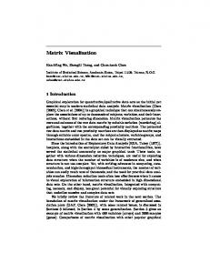
HealthVisB presents users with an interface organized around a single manipulable map (figure 1). Surrounding the map are tools that allow the user to control spatial, temporal, and attribute features of the display. Spatial manipulation is limited to selection among three boundary choices, using a button that toggles among: U.S. outline only, U.S. plus states, or U.S. plus health service areas (HSAs). Several controls relate to attribute information. Three pull down menus (top left) allow users to select a mortality cause, a risk factor, and a data classification scheme (a data%to%display mapping) for either or both. Data classification and color scheme options for the mortality cause data include: a 5-class diverging scheme (color figure 1), a 7-class diverging scheme (color figure 2), and dynamic focusing&a 2-class binary scheme with a user controllable break point having a 5% step size (color figure 3). When a cause and a risk factor are both displayed with binary representation, the resulting 4-category map is what Monmonier [29] has called a "cross map" (figure 1 and color figure 4). Here, cross maps allow binary focusing on each variable (in contrast to a standard bivariate map with multiple, usually fixed, category break points). This allows analysts to concentrate on spatial correspondence of extremes (e.g., locations with high mortality rates that also have low per capita income). Users can apply focusing by clicking VCR style forward and reverse but-
The HealthVisB temporal controls implement three of the four categories identified by Rheingans [34] for interactive control of a sequence of linked views. Her categories recognize two components of control having two states each: smoothness of transition between views (discrete or smooth) and level of manipulation control given to the user (over just pace of a predetermined sequence or "complete control," over both pace and order of views). HealthVisB implements both discrete and smooth control of pace (through the advance-reverse buttons and the pace control, respectively), and discrete adjustment of a "complete control"&provided by the ability to click and drag the time marker. Smooth complete control (that updates the display continuously as the marker is dragged) was not implemented due to the small number of time steps available. Thus, the interface uses what Rheingans [35] calls "interactive" rather than "dynamic" manipulation.1
4.2 Examining subsets over time Tools for dynamic manipulation of focusing retain their settings across times. This allows an analyst to focus on high or low values, then animate (or step through) the time series in an effort to identify spatiotemporal patterns for the subset of data highlighted. This method of visual analysis works for both univariate maps of mortality and bivariate maps of mortality crossed with risk.
4.3 Comparing change over time Focusing controls are retained, not only across time steps for a variable, but as a user moves among variables (either multiple mortality causes or multiple risk factors). As a result, a portion of the data range for two variables can be compared by switching back and forth between them. When classification is set to 5- or 7-class maps, the system retains that classification setting as well, facilitating comparison of the full map pattern.
5 CHARACTERIZING EXPERT USE
Figure 1. A sample display layout illustrating the full set of available controls applied to a bivariate “cross” map (see above). On each cross map blue is used to indicate higher mortality rates (see the color plate) and dark shades depict higher values for the risk factor.
Very little is known about how domain specialists apply GVis tools for data exploration and/or hypothesis generation, thus a narrow controlled experiment designed to measure success of tools for specific tasks was not appropriate. Instead, we use a carefully structured qualitative sequential analysis approach to characterize domain experts’ use of the prototype for pursuing
typical data exploration goals. Evidence generated is not intended to test specific hypotheses but to develop an understanding of data exploration strategies as they are facilitated (or might be facilitated) by GVis tools and, thus, to both inform system design and to prompt hypotheses for further research.
5.1 Method All participants worked with three georeferenced age-adjusted data sets for mortality (heart disease, lung cancer, and prostate cancer rates/100,000 population for 1979-81, 1982-84, 1985-87, 1988-90, and 1991-93) and a pair of possible "risk factors" for the same years (per capita income and unemployment). All data were aggregated to 798 health service areas for the conterminous U.S. During each session, information collected about system use included verbal commentary from participants and system generated logs of all interactions (including time of each "event"). Solicitation (and subsequent analysis) of verbal comments is based on principles of protocol analysis [13]. Participants were asked to comment (as they worked) on what they were doing (i.e., system interactions), and what they were seeing (i.e., map and system interpretations). They were specifically asked not to justify their actions or to make recommendations about the system or map (until the end of the session). All participants were individuals doing research on the analysis of health data and/or demographic data to which health statistics are typically related (specialists in epidemiology, biostatistics, demography, health policy analysis, or medical geography). They included five individuals from the U.S. National Center for Health Statistics and four from the Penn State Population Research Institute. Three were senior PhD students, and the remainder hold a Ph.D. Only one had significant expertise in application of mapping or GIS to health or related statistics. Since the participants were not Geographic Information Science experts, an introduction to the prototype and demonstration of its use was provided prior to having participants work with the system. Each session was conducted by the lead author, who introduced the system, presented data exploration goals, answered any questions, and conducted an exit interview. All sessions were videotaped. To insure consistency, a "script" was used as a guide to the system demonstration (see the project web site, url above, for the full script). Following the system demonstration, each participant spent several minutes experimenting with the system. Then the participant was asked to complete six data exploration modules, three of which are considered here (figure 2). The total session lasted from 45 minutes to one hour.
5.2 Evidence A combination of interaction logs and verbal protocols yields a rich set of evidence concerning system use and visual thinking prompted by that use. A first step in processing this information was to transcribe verbalizations from the videotape and create an initial parsing into units based on clear pauses or shifts in topic. Once a draft transcript was created, the video was watched again to identify transcription errors and to tag each verbal unit with its start time (used to link verbal units with interaction logs). MacSHAPA, a software environment for exploratory sequential data analysis [38] was used to organize and analyze the combined verbalization and system log data. In MacSHAPA, data are
organized in a spreadsheet with rows representing time during a session and columns representing categories of "event"&a verbalization by the participant, a response from the investigator, postsession interpretation by the investigator, or an action logged by the system. During processing, many verbalization units were further subdivided to facilitate detailed analysis. Several tools for exploring complex sequential data are provided in MacSHAPA. Five used extensively are described here briefly: (1) Timelines: interactive graphs in which categories of event (spreadsheet columns) are represented by a line plot depicting times at which each event took place; (2) Cycle reports: a tree diagram of all "events," in a specified column, between instances of two other events; (3) Content reports: a tabulation of event frequency within the subset of data currently specified; (4) Listing report: a list of user generated system events (e.g., mouse clicks on controls) and event times; (5) Filtering: an alternative method (to a cycle report) for selecting a subset of information from a spreadsheet column (or columns). Filtering allows the analyst to examine all instances of one or more event types. MacSHAPA is designed for analysis of individual time series data, not for comparison across subjects. Thus, it is used to develop characterizations of each participant and to generate summary data from which comparisons among participants are carried out. As noted above, the goal of analysis is to characterize system use by domain experts, not to test predetermined hypotheses concerning that use. These characterizations can be used to inform development of visualization methods that match expert knowledge schemata and exploration strategies and/or to guide design of training materials that might be needed to help individuals who are domain (but not visualization) experts learn to take full advantage of dynamic GVis environments. The characterizations also contribute to the broader goal of understanding how GVis tools might change the way experts explore their data.
We will begin with heart disease. Here is the first aspect of heart disease that we would like you to consider. With this and subsequent lists, please read the instructions and ask for clarifications if necessary before clicking the "start module" button. Remember to talk aloud while working. 1. Consider heart disease for white males a. where are the lowest mortality rates located? b. where are the highest mortality rates located? c. where are the national median mortality rates located? 2. Continue with heart disease for white males a. examine the time trend and describe any geographic changes in location of high, low, or median mortality rates over time b. consider whether there is any change in the number of clusters or size of clusters over time 3. Compare the time trend of heart disease to that of lung cancer (both for white males), focusing on a. similarity or difference in location of highest mortality rate areas over time b. change in geographical correspondence between the 2 mortality causes from time 1 to time 2 (do the patterns become more or less closely matched over time) Figure 2. Instructions for the three exploration modules reported on here (see project url for modules 4-6).
5.3 Results Here we comment briefly on participant understanding of the prototype’s maps and controls, then we present a characterization, by module, of each participants’ prototype use.
5.3.1 Map symbolization and interactive controls General reactions to the diverging color scheme used on the univariate mortality rate maps were positive. This was expected, because the color scheme used was the one for which performance was best in previous research [4]. That the scheme was interpreted correctly by all participants, indicates that these previous results (with paper maps) are relevant for screen display maps. Two participants found the color scheme used on the bivariate cross maps hard to interpret (due to low contrast between two of the four colors) and a few participants thought that the two-by-two cross map should be replaced with a five-by-two or seven-by-two map (to provide more detail). Interactive controls in the prototype were of two main kinds, menus and direct manipulation tools embedded in the map display. All participants seemed familiar with menus and encountered few difficulties with them. The direct manipulation controls proved to be generally successful. Most participants used most controls and there were few negative comments or mistakes in their use. For manipulating mortality cause and risk factor information, six participants used both discrete controls (buttons that move focusing sequentially through the data range) and continuous controls (sliders that could be dragged to a particular data break point), with two others using only discrete controls and one using only continuous. For manipulating time, however, discrete control was dominant with only three participants using the continuous control, and two of those using it infrequently.
5.3.2 Spatial pattern analysis & module 1 Although HealthVisB is designed primarily to facilitate spatiotemporal analysis, it includes tools that support spatial pattern analysis at specific times. The first module that participants were asked to complete focused on spatial pattern analysis alone and was designed to help orient participants to the system and to serve as a base against which to compare subsequent strategies for space-time exploration. Participants were asked to consider, for time period one, the location of highest, lowest, and median mortality rates (figure 2). The starting point for all participants was the default 7-class map that used a diverging color scheme (ranging from dark purple for the highest rates through gray, for the national median rate, to dark green for the lowest rates%see color figure 2). The three task goals could be addressed directly using the default map but high and low rates are more clearly seen using the focusing control to highlight them. Both the 5-class map (color figure 1) and the 7class map (color figure 2) are useful when examining the median rates because the category spanning the median is shown in gray. The initial module did not prompt much interaction with the system. As illustrated in figure 3, four participants made modest use of focusing to highlight highs and lows while four relied exclusively on the default 7-class map (one, P4, used the 2-class map non-interactively together with the 5-class map). Of the four participants who relied on the default 7-class map, all noticed
50 0 anim:maps time:shift cause:focus class:select 1
2
3
4
5
6
7
8
9
Figure 3. Frequencies for key actions (or maps seen) during module 1 % by participant along the X-axis and by kind of action along the Y-axis. The front row (class:select) represents the number of times the classification method was changed (e.g., from a 7-class map to a manipulable 2-class map). The second row (cause:focus) depicts the number of times that cause focusing was adjusted. The third row (time:shift) depicts the number of times that position in time was manipulated by either stepping time (with the VCR arrow) or moving directly to a time with the time slider. Rather than depicting frequency of control actions, the back row (anim:maps) represents the number of maps seen using animation (5 times the number of full animation cycles watched). The total can result from one or many uses of animation. Tabular data for all user interactions is available on the project web site (url above).
that the east has higher rates than the west, but none noticed that there are two major clusters of high rates in the east (one in the northeast%Appalachia region and one along the eastern seaboard, from Maryland through Georgia). Of the four participants who used focusing, all noted the two distinct clusters of high values in the east (along with some more subtle differences). The one participant who selected (but did not interact with) the 2-class map identified the basic east-west difference in rates but seemed to forget that values in the top half of the distribution are not all high rates. When considering low rate areas, three of the four participants who relied on the 7-class map noticed that Florida has particularly low rates. Two of the four who used focusing noticed the low Florida rates, while the other two focused on the bottom 5 or 10%, missing Florida (where locations begin to appear as focusing moves to the 15th or 20th percentile). One person who used focusing to explore high and low values, then failed to realize that the best method for exploring median rates was to switch back to the 7- or 5-class map and, thus, was not able to characterize the distribution of median rates.
5.3.3 Time series analysis & module 2 Heart disease mortality was selected as the variable for participants to work with initially because it has clear spatial patterns and because it has a definite spatial change over time (in location of the largest clusters of high values, from the northeast and northern Appalachia toward the south and west). The spacetime exploration goal posed here (see figure 2) prompted considerable use of map manipulation capabilities, with all participants using either time stepping or animation (six of nine using both). Several clear exploration strategies are apparent, in both the composite frequency graph (figure 4) and in individual timelines (figure 5). One group of participants favored animation (P6, P7, P8, P9, with P6 running the animation continuously during the module, for 26 cycles), a second group favored time stepping (P3, P4), a third balances methods (P1, P5), and one individual (P2) made limited use of either temporal analysis control.
P1 250 200 150 100
00:00
05:00
P2
10:00
P:ex M:st M:ex B:ch S:tu C:se Cl:s R:se C:st C:mo R:st R:mo D:st D:mo A:st A:pa A:re A:sp
05:00
10:00
15:00
00:00
05:00
10:00
00:00
05:00
10:00
00:00
05:00
10:00
P:ex M:st M:ex B:ch S:tu C:se Cl:s R:se C:st C:mo R:st R:mo D:st D:mo A:st A:pa A:re A:sp
50 0 anim:maps time:shift cause:focus class:select 1
2
3
4
5
6
7
8
9
Figure 4. Frequencies for key actions (or maps seen) during module 2. See figure 3 for explanation of axes and project web site for data.
Since the shift in heart disease mortality over time is primarily in location of the top 20% of mortality rates, this space-time pattern is most easily seen by focusing the cause to the 80th percentile (or higher) and then animating the map at a slow to medium speed. Examined in this way, the shift is fairly dramatic and, once noticed, can be observed in an animation of the default 7-class map or in static printed (relatively high resolution) small multiples (color plate 5). Without prior knowledge of what to look for (knowledge that readers of this paper now have) the time trend is quite hard to discern using either animated 7-class maps or small multiples at typical screen display resolution. Only three of nine participants noticed the key shift toward the south and west in the core of high values for heart disease mortality. All three (P6, P8, and P9) made substantial use of animation. Two of these noticed the shift immediately (without using focusing) and one saw it only after focusing to the 90th percentile and rerunning the animation. In general, it seems that either viewing the animation many times (as P6 and P9 did), or using animation together with focusing (as P8 did), facilitates the identification of subtle spatiotemporal patterns. Those who did not use animation or viewed only one or two cycles through the time series missed the trend, as did one participant who used focusing with animation but never focused above the 75th percentile. Although success in noticing the change in position of clusters over time was achieved by only a few participants (and seemed to require a particular strategy), several participants (using varied strategies) were successful in identifying a change in spatial concentration of heart disease over time (P1, P2, P3, P5, P6, P8, and P9). The pattern noticed was a general dispersal of major clusters over most of the time period with some reaggregation in the final time period (the latter noticed by only two participants).
5.3.4 Space-time comparisons & module 3 For module 3 (see figure 2), as with module 2, most participants made extensive use of available tools (figure 6). The patterns of animation and time stepping are similar to those above, the main difference being that (in this module) P1 and P5 rely exclusively on time stepping, rather than balancing their use of time stepping with animation. Three participants toggled back and forth repeatedly between causes.
P3
00:00
P4
05:00
P:ex M:st M:ex B:ch S:tu C:se Cl:s R:se C:st C:mo R:st R:mo D:st D:mo A:st A:pa A:re A:sp
P:ex M:st M:ex B:ch S:tu C:se Cl:s R:se C:st C:mo R:st R:mo D:st D:mo A:st A:pa A:re A:sp
P5
00:00
05:00
P6
10:00
P:ex M:st M:ex B:ch S:tu C:se Cl:s R:se C:st C:mo R:st R:mo D:st D:mo A:st A:pa A:re A:sp
P:ex M:st M:ex B:ch S:tu C:se Cl:s R:se C:st C:mo R:st R:mo D:st D:mo A:st A:pa A:re A:sp
P7
00:00
05:00
P8
10:00
P:ex M:st M:ex B:ch S:tu C:se Cl:s R:se C:st C:mo R:st R:mo D:st D:mo A:st A:pa A:re A:sp
P9 P:ex M:st M:ex B:ch S:tu C:se Cl:s R:se C:st C:mo R:st R:mo D:st D:mo A:st A:pa A:re A:sp
15:00
P:ex M:st M:ex B:ch S:tu C:se Cl:s R:se C:st C:mo R:st R:mo D:st D:mo A:st A:pa A:re A:sp
00:00
05:00
10:00
15:00
P:ex M:stM:exB:chS:tuC:seCl:sR:seC:stC:moR:stR:moD:stD:moA:stA:paA:reA:sp-
program execute module start module exit boundary change scatterplot turn cause select class select risk select cause step cause move risk step risk move date step date move animate start animate pace animate rewd animate stop
Figure 5. Timelines for the nine participants. Each set includes a timeline for each interface control, whether or not it was used. For controls that are used, the timeline includes a tick mark for every instance of use. Dashed vertical lines highlight the start/end of the three modules. Due to scaling, the dark areas on the timelines often represent many repeated events.
All participants recognize the general similarity in patterns of high rates for the two causes. Six (P3, P5, P6, P7, P8, P9) note some of the general differences (either concentrating on the more southerly pattern of high rates for lung cancer in the east and/or the relatively high rates for lung cancer in the far west). Four of these six made substantial use of animation and one used time stepping extensively. Three participants (P1, P3, P4) who failed
150 100 50 0 anim:maps time:shift cause:focus class:select 1
2
3
4
5
6
7
8
9
Figure 6. Frequencies for key actions (or maps seen) during module 3. See figure 3 for explanation of axes and the project web site for data.
to notice the shift in high heart disease mortality rates over time in module two noticed that shift here. All use time stepping exclusively, but frequently, in this module. Of the three remaining participants who failed to notice the shift in heart disease during either module, two (P2, P5) were very conservative in their use of temporal controls. Over time, lung cancer is considerably more stable (geographically) than heart disease and the two mortality causes become more similar (particularly in the location of the top quarter of the rates). One participant (P1) noted both trends, three noted the difference in stability (P3, P4, P7) and two noted the increased correspondence (P6, P9).
6 CONCLUSIONS AND FUTURE WORK Using a structured three-level approach to GVis design we identified a set of conceptual goals for a GVis system intended for analysis of time series georeferenced health statistics. Necessary operations on data that facilitate addressing those goals were then identified. Two sets of operations were been implemented in a pair of rapid prototypes, one of which (HealthVisB) was described in detail and its use by domain experts formally examined here. Characterizing expert information exploration strategies is a fundamental step in refining exploratory visualization methods and in understanding the implications of their use in science and decision making. We employed qualitative sequential data analysis methods to characterize the strategies (and success) of nine domain experts who used HealthVisB to address a series of semistructured data exploration goals. The data exploration methods implemented can be considered successful. Participants had few problems understanding how to use the maps and tools provided and problems that did arise are ones that can be dealt with by modest redesign and/or development of brief training modules. Few obvious Type I visualization errors (seeing false patterns) occurred, but a number of Type II visualization errors (missing real patterns) were noted. For the latter, differences in success at noticing spatiotemporal patterns relate to differences in data exploration strategies adopted. One example of a clear difference in success with different strategies relates to the two general approaches adopted for considering time series (manual stepping through time with a discrete VCR style control and use of a looping animation). Three of the four participants who favored animation over manual date stepping noticed a distinct
shift in location of high heart disease mortality rates over time. None of the five who favored manual time stepping noticed this shift initially, although three noticed it later in the session after much more time stepping had been done. Implementation of HealthVisB and detailed observation of domain experts using it for typical data exploration tasks provides a base for subsequent research. The general success of the prototype suggests that an effort is needed to more completely integrate spatiotemporal visualization methods into currently nontemporal GIS. Initial identification of different exploration strategies by domain experts should be followed by more detailed analysis of these strategies to determine which are effective for particular kinds of exploration and whether the effective strategies can be integrated into GVis software (perhaps in the form of routines that prompt less experienced analysts to use expert strategies). Particularly intriguing results are the apparent advantages of animation over discrete time stepping and of focusing over standard 7-class maps. These advantages, of course, need to be verified in controlled experiments that consider independently the various parameters of animations and manipulable maps that might lead to success or failure (e.g., animation pace, number of time steps, number of times each map is seen, smoothness of transition from scene to scene, availability of data focusing, dynamic manipulation versus simple interaction, etc.). Geographic data are important in may aspects of science and society. GVis methods can facilitate use of these data in scientific reseearch and in decision making, but only if we develop a better understanding of how scientists or decision makers conceptualize problems, explore data, generate hypotheses or possible problem solutions, and use information visualization tools in these activities.
Acknowledgments Research was supported by a contract from the U.S. Centers for Disease Control, National Center for Health Statistics, # 0009630348. Support was also provided by the Penn State Center for Academic Computing, where MacEachren is a 1998-99 faculty fellow. The authors thank Colin Polsky, David Brown, Jaishree Beedasy, and Mark Marrara for contributions to early stages of the project and Adria Lizka and Jeff Balmat for assistance with data processing.
References [1] [2]
[3]
[4]
[5]
[6]
Becker, R. A. and Cleveland, W. S. 1987. Brushing Scatter plots. Technometrics, 29: 127-142. Bertin, J. 1983. Semiology of Graphics: Diagrams, Networks, Maps. Madison, WI: University of Wisconsin Press (English translation of the French original, 1969). Brewer, C. A. 1994. Color use guidelines for mapping and visualization. Visualization in Modern Cartography. Oxford, UK, Pergamon. A. M. MacEachren and D. R. F. Taylor ed. 123-147. Brewer, C. A., MacEachren, A. M., Pickle, L. W. and Herrmann, D. 1997. Mapping mortality: evaluating color schemes for choropleth maps. Annals of the Association of American Geographers 87(3): 411-438. Buja, A., McDonald, J. A., Michalak, J. and Stuetzle, W. 1991. Interactive data visualization using focusing and linking. Proceedings, Visualization '91, San Diego, CA, IEEE. 156-163. Campbell, C. S. and Egbert, S. L. 1990. Animated cartography: Thirty years of scratching the surface. Cartographica, 27(2): 24-46.
[7]
[8]
[9]
[10]
[11] [12]
[13] [14] [15]
[16]
[17]
[18] [19]
[20]
[21] [22]
[23]
[24]
[25]
[26]
[27]
Carr, D. B., Littlefield, R. J., Nicholson, W. L. and Littlefield, J. S. 1987. Scatterplot matrix techniques for large N. Journal of the American Statistical Association, 82(398): 424-436. Chen, M.-S. and Hung, S.-C. 1995. Cognitive approach in an icon-based human computer interface design. Journal of Information & Optimization Sciences 16(3): 579-584. Croner, C. M., Pickle, L. W., Wolf, D. R. and White, A. A. 1992. A GIS approach to hypothesis generation in epidemiology. ASPRS/ACSM/RT '92, Washington, D. C., August 3-8, 1992, ASPRS/ACSM. 275-283. DiBiase, D., Reeves, C., Krygier, J., MacEachren, A. M., von Wyss, M., Sloan, J. and Detweiller, M. (1994). Multivariate display of geographic data: Applications in earth system science. Visualization in Modern Cartography. Oxford, UK, Pergamon. A. M. MacEachren and D. R. F. Taylor ed. 287-312. Dykes, J. 1997. Exploring spatial data representation with dynamic graphics, Computers & Geosciences, 23(4): 345-370. Eddy, W. F. and Mokus, A. 1994. An example of the estimation and display of a smoothly varying function of time and space % The incidence of the disease mumps. Journal of American Society for Information Science 45(9): 686-693. Ericsson, K. A. and Simon, H. A. 1993. Protocol Analysis: Verbal reports as data. 2nd ed. Cambridge, Mass.: MIT Press. Foley, J. D., van Dam, A., Feiner, S. K. and Hughes, J. F. 1990. Computer Graphics: Principles and Practice. Reading: Addison-Wesley. Gould, P., DiBiase, D. and Kabel, J. 1990. Le SIDA: la carte animee comme rhetorique cartographique appliquee. Mappe Monde, 90(1): 21-26. Haug, D., MacEachren, A. M. Boscoe, F., Brown, D., Marrara, M., Polsky, C. and Beedasy, J. 1997. Implementing exploratory spatial data analysis methods for multivariate health statistics. Proceedings of GIS/LIS ‘97 Cin., OH, Oct. 28-30, 1997, pp. 205-212. Howard, D. and MacEachren, A. M. 1996. Interface design for geographic visualization: Tools for representing reliability. Cartography & Geographic Information Systems, 23(2): 59-77. Kousoulakou, A. and Kraak, M. -J. 1992. Spatio-temporal maps and cartographic communication. Cartographic Journal 29(2): 101-108. Kraak, M.-J., Edsall, R. and MacEachren, A. M. 1997. Cartographic animation and legends for temporal maps: Exploration and or interaction. 18th International Cartographic Conference, Stockholm, June 23-27, 1997, ICA, pp. 253-262. Lindholm, M. and Sarjakoski, T. 1993. User interface in a computer atlas. 14th International Cartographic Conference Cologne, Germany, May 3-9, 1993, pp. 613-627. MacEachren, A. M. 1995. How Maps Work: Representation, Visualization and Design. Guilford Press. MacEachren, A. M. and DiBiase, D. W. 1991. Animated maps of aggregate data: Conceptual and practical problems. Cartography and Geographic Information Systems, 18(4): 221-229. MacEachren, A. M., Howard, D., von Wyss, M., Askov, D. and Taormino, T. 1993. Visualizing the health of Chesapeake Bay: An uncertain endeavor. Proceedings, GIS/LIS '93 Minneapolis, MN, 2-4 Nov., 1993, pp. 449-458. MacEachren, A.M. and Kraak, M.-J. 1997. Exploratory cartographic visualization: Advancing the agenda. Computers and Geosciences, 23(4): 335-344. MacEachren, A. M., Polsky, C., Haug, D., Brown, D., Boscoe, F., Beedasy, J., Pickle, L. and Marrara, M. 1997. Visualizing spatial relationships among health, environmental, and demographic statistics: interface design issues. 18th Int. Cartographic Conf. Stockholm, June 23-27, pp. 880-887. Marr, D. 1985. Vision: The philosophy and the approach. in A. M. Aitkenhead and J. M. Slack, eds. Issues in cognitive modeling. London: Erlbaum, 103-26. McGuinness, C. 1994. Expert/novice use of visualization tools. In Visualization in Modern Cartography, ed. A. M. MacEachren and D. R. F. Taylor, pp. 185-200. London: Pergamon.
[28] Monmonier, M. 1989. Geographic brushing: Enhancing exploratory analysis of the scatterplot matrix. Geographical Analysis, 21(1): 8184. [29] Monmonier, M. 1992. Authoring graphic scripts: Experiences and principles. Cartography and Geographic Information Systems 21(1): 37-47. [30] Monmonier, M. and Gluck, M. 1994. Focus groups for design improvement in dynamic cartography. Cartography and Geographic Information Systems 21(1): 37-47. [31] Olson, J. M. 1981. Spectrally encoded two-variable maps. Annals of the Association of American Geographers, 71(2): 259-276. [32] Pickle, L. W. and Herrmann, D. J., ed. 1995. Cognitive Aspects of Statistical Mapping. Washington, D. C.: Centers for Disease Control and Prevention/National Center for Health Statistics, Office of Research and Methodology. [33] Pickle, L. W., Mason, T. J., Howard, N., Hoover, R. and Fraumeni, J. F. J. 1987. Atlas of U. S. Cancer Mortality among Whites: 1950-1980. Washington, D. C., USGPO. [34] Rheingans, P. 1992. Color, change, and control of quantitative data display. Proceedings, Visualization '92 October 19-23, Boston, Mass., pp. 252-259. [35] Rheingans, P. 1997. Dynamic color mapping of bivariate qualitative data. Proceedings, Visualization '97 October 19-24, Phoenix, AZ, pp. 159-166. [36] Rheingans, P. and Tebbs, B. 1990. A tool for dynamic explorations of color mappings. Computer Graphics, 24(2): 145-146. [37] Robertson, P. K. and O'Callaghan, J. F. 1986. The generation of color sequences for univariate and bivariate mapping. IEEE Computer Graphics and Applications Feb.: 24-32. [38] Sanderson, P., Scott, J., Johnston, T., Mainzer, J., Watanabe, L. and James, J. 1994. MacSHAPA and the enterprise of exploratory sequential data analysis (ESDA). International Journal of Human-Computer Studies 41: 633-681. [39] Trumbo, B.E. 1981. A theory for coloring bivariate statistical maps. The American Statistician, 35(4): 220-226. [40] Tufte, E. 1983. The Visual Display of Quantitative Information. Cheshire, Conn.: Graphics Press. [41] Winn, D. M., Blot, W. J., Shy, C. M., Pickle, L. W., Roledo, A. and Fraumeni, J. F. J. 1981. Snuff dipping and oral cancer among women in the southern United States. New England Journal of Medicine, 304: 745-749.
Notes 1. A less choppy animation would result if temporal interpolation and smoothing were used (see [12] for an example of spatial and temporal smoothing applied to georeferenced health statistics). Data available, however, were already smoothed (three year averages), and contained only 5 time slices, thus interpolation and further smoothing was not appropriate. Our data were at relatively high spatial resolution with 798 HSAs compared to the 48 states used in [12]. One design criterion for the prototype was that the expert users be able to consider both broad regions and individual HSAs, thus spatial smoothing was not applied.
Color figure 1. Example 5-class map of the same data shown in color figure 1. In this case, state rather than HSA boundaries are shown (although data still represent the smaller units).
Color figure 3. Focusing applied to the data set depicted above. Here, HSAs in the top quartile for white male age adjusted heart disease mortality rates in 1979-81 are shown.
Color figure 2. Example 7-class map using a diverging scheme (dark purple, medium purple, light purple, gray, light green, medium green, dark green) matched to the range of data from high (dark purple) through median (gray) to low (dark green). This color scheme puts emphasis on the two extremes and on the middle of the range. The map depicts white male age-adjusted heart disease mortality rates by health service area in the conterminous U.S. over a three year time period (1979-81).
Color figure 4. A bivariate cross map depicting white male age-adjusted heart disease mortality rates in 1979-81 crossed with per capita income. Both variables are focused to the 80th percentile. Blue represents HSAs with a mortality rate in the top 20% and gray depicts mortality rates below this threshold. Dark shades represent per capita income in the top 20% and light shades depict income below this level. Thus, light blue depicts HSAs with a high rate of heart disease and low income.
Color figure 5. Small multiples depicting the 5 time steps for heart disease mortality rates.