bets from a single hand motion using Hidden Markov Models (HMM). In our method ..... for testing (totally, 520 video for trained gestures and 260 for tested ...
Gesture Recognition for Alphabets from Hand Motion Trajectory Using Hidden Markov Models Mahmoud Elmezain, Ayoub Al-Hamadi, Gerald Krell, Sherif El-Etriby, Bernd Michaelis Institute for Electronics, Signal Processing and Communications (IESK) Otto-von-Guericke-University Magdeburg D-39016 Magdeburg, P.O. Box 4210 Germany {Mahmoud.Elmezain, Ayoub.Al-Hamadi}@ovgu.de
Abstract— This paper describes a method to recognize the alphabets from a single hand motion using Hidden Markov Models (HMM). In our method, gesture recognition for alphabets is based on three main stages; preprocessing, feature extraction and classification. In preprocessing stage, color and depth information are used to detect both hands and face in connection with morphological operation. After the detection of the hand, the tracking will take place in further step in order to determine the motion trajectory so-called gesture path. The second stage, feature extraction enhances the gesture path which gives us a pure path and also determines the orientation between the center of gravity and each point in a pure path. Thereby, the orientation is quantized to give a discrete vector that used as input to HMM. In the final stage, the gesture of alphabets is recognized by using Left-Right Banded model (LRB) in conjunction with Baum-Welch algorithm (BW) for training the parameters of HMM. Therefore, the best path is obtained by Viterbi algorithm using a gesture database. In our experiment, 520 trained gestures are used for training and also 260 tested gestures for testing. Our method recognizes the alphabets from A to Z and achieves an average recognition rate of 92.3%. Keywords— Hidden Markov Model, Gesture recognition, Pattern recognition, Application.
I. I NTRODUCTION Sign language recognition from hand motion or hand posture is an active area in gesture recognition research for Human Computer Interaction (HCI). Hand gesture recognition has many applications such as: Sign Language Recognition [1], Communication in Video Conference [2], Using a finger as a pointer for selecting options from menu [3] and Interacting with a computer by easy way for children [4]. Over the last few years, many methods for hand gesture recognition have been proposed [5, 6, 7, 8, 9, 10]. These methods differ from one another in their models; Neural Network [5], Syntactical Analysis [6] and Hidden Markov Model [7]. Pashalo et. al. [8] have developed a system that could recognize both isolated and continuous Greek Sign Language (GSL) sentences where orientation vector is extracted from images and used in sentences as input to HMM. Tanibata et. al. [9] introduced a method to obtain features from sequence of images where a person is performing the Japanese Sign Language (JSL) in a complex background and to recognize the JSL word. Binh et. al. [10] introduced a hand gesture recognition system to recognize real time gesture in unconstrained environments and the system
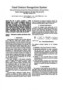
was tested to vocabulary of 36 gestures including the American Sign Language (ASL) letter spelling alphabet and digits. Yoon et. al. [6] introduced a hand gesture recognition method which used a combined features of location, angle and velocity to determine the discrete vector that is used as input to HMM. In shortly, a gesture is a spatio-temporal pattern [11] and may be static or dynamic or both as in sign language recognition. Since HMM are used widely in handwriting, speech recognition, part-of-speech tagging and machine translation, therefore in contrast to Liu et. al. [11], we develop a method to recognize the gesture hand graphical from A to Z using Hidden Markov Model take in our account the orientation between any point in a pure path and the center of gravity in the graphical gesture. The method depends on the database which we built it and Left-Right Banded model (topology of HMM) with 6 states. Each alphabet is based on 30 video (20 for training and 10 for testing) where the input images are captured by a Bumblebee stereo camera that has 6mm focal length for about 2 to 5 second at 15 frames per second with 240 × 320 pixels image resolution on each frame. The recognition rate is achieved on training and testing gesture with 98.46% and 92.3% respectively. The next sections describe how the method is built and gesture hand graphical is tested. The paper is organized as follows; Section 2 demonstrated with the suggested method in three subsections. The experimental results are described in Section 3. Finally, the summary and conclusion is presented in Section 4. II. SUGGESTED METHOD Our method is designed to classify the gesture path that generated from a single hand motion by using HMM. In particular, the alphabet gesture method consists of three main stages (Fig. 1). (1) Preprocessing; localize and track the hand to generate its motion trajectory (gesture path). (2) Feature extraction; enhance the gesture path and then determine the discrete vector by quantization the orientation. (3) Classification; the gesture hand graphical is recognized by using discrete vector and Left-Right Banded (LRB) model with 6 states.
The 7th IEEE International Symposium on Signal Processing and Information Technology (ISSPIT 2007)
1209
Images Sequence
2.1 Preprocessing
2.2 Feature Extraction 2.3 Classification (a) Original image
Skin Color Detection
Pure path
Gesture Database
Hand Tracking
Vector Quantization
Hidden Markov Models
Gesture Recognition
Fig. 1.
Suggested method for alphabets gesture recognition using HMM
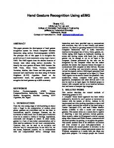
A. Preprocessing Preprocessing is the first stage in our method which contains two steps. The first step is skin color detection and the second step is hand localization and tracking. In the first step, Y Cb Cr color space is used where Cb and Cr channels represent chrominance and Y channel refers to brightness [2, 12]. We ignore Y channel in order to reduce the effect of brightness variation and then use only the chrominance (Cb , Cr ) channels which are fully representing the color. In a chrominance plane, human skin color is found in a small area, so each pixel is classified by using a lookup table. If the pixel lies in skin color range, it is classified as skin pixel (value=1) or non skin pixel (value=0) otherwise. Thus, we obtain the binary image of skin color by using a threshold and the depth information that is determined by a Bumblebee stereo camera. By the given depth information from the camera set-up system, the depth value for each skin pixel is found during the skin detection. Then the mean depth for each region is calculated. Therefore, the problem of overlapping between hands and face is solved since the hands regions be closer to the camera rather than the face region. For removing the outliers (noise, spurious components) from a binary image, we use morphological operation such as: median filter, erosion and dilation since there are small regions that are close to skin but are not belong to the human body. Furthermore, the holes pixels are fills on the outer edge of an image that are not connected to the background. Thereby, the skin color is detected (hands and face) taking in our consideration the person is wearing T-shirts with tall sleeves. Fig. 2 shows the skin segmentation and hand localization where the first frame of the images sequence is represented in Fig. 2(a). Fig. 2(b) illustrates the detected regions in labeled color (hands and face). Fig. 2(c) refers to the centroid points and the bounding box of the hand detection area. In the second step (hand localization and tracking), the localization of two
Fig. 2.
(b) Skin detection
(c) Hand localization
Skin segmentation and hand localization
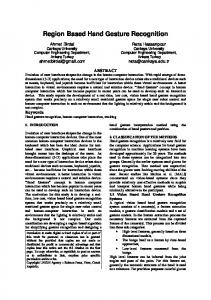
hands is found by choosing the two small areas where a face represents the big area and the furthest away from the camera. Our attention concentrates to the motion of a single hand to detect the hand graphical trajectory for a specific alphabet. Moreover, we use a blob analysis to determine the centroid point, boundary area and the bounding box of a hand region. Consequently, we take a search area in the next frame around the bounding box that is determined from the last frame in order to track the hand and reduce calculation region take in our consideration the speed of moving hand. If there is an extracting multiple skin regions in a search area of the hand, a big region is selected since this region represents a hand at mostly. Thereby, the new bounding box is calculated and the centroid point is determined. By iteration of this process, the motion trajectory of the hand so-called gesture path is generated from centroid points connection (Fig. 3).
Fig. 3.
Gesture path for D and M alphabets
B. Feature Extraction The feature extraction is a very important part in our method to recognize the alphabet gesture path. There are three basic features as location, orientation and velocity. The previous researches [6, 11] showed that the using of orientation feature
The 7th IEEE International Symposium on Signal Processing and Information Technology (ISSPIT 2007)
1210
No motion
Gesture path Check start
n
Motion
µ No motion
θt = arctan
Check end
•
•
Gesture path enhancement
Firstly, the gesture path is entered to a check start state to see, if there is no motion then it takes the next point, else the pure path is begin generated. Secondly, the pure path state continues to generate the pure path while the points of gesture path input move. When the point not moves, we call to the check end state. Finally, the pure path is generated from the check end state when the input gesture path ended (i.e. there is no points). Also, while there are points in gesture path, this state perform a check to see if the point not moves then delete it and takes the next point, else return to the pure path state.
In contrast to the enhancement gesture path to obtain a pure path, our method is based on the angle (orientation) as a basic feature. Therefore, the orientation is based on (Xc , Yc ) where Xc and Yc are the center of gravity for pure path and are determined by Eq. 1 and Eq. 2. Since the location of pure path for the same gesture according to the start point is different, we calculate the orientation between any point in pure path and the center of gravity (Fig. 5). 90°
Y (xt+1 ,yt+1) 5
(xt ,yt)
(xt-1 ,yt-1) șt
180°
(XC ,YC)
4 3 2
6 7 8
X
9 10
1 12 11
270° Fig. 5.
1X yt n t=1
Yc − yt Xc − xt
(2)
¶ ; t = 1, 2, ..., n
(3)
where n is the length of pure path. In addition, we determine the orientation θt according to Eq. 3 where the orientation is divided by 30◦ in order to quantize the value of it from 1 to 12. Thereby, the discrete vector is obtained which is used as input to HMM.
is the best in terms of results. So, we will rely upon it in our method. A gesture path is spatio-temporal pattern which consists of centroid points (Xhand , Yhand ). The gesture path may be containing unmovable points notably at the first and end of gesture path, so we enhance the gesture path to obtain a pure path as follows (Fig. 4) : •
Yc =
(1)
n
Pure path Motion
Fig. 4.
1X xt n t=1
Motion
No motion
Pure path
Xc =
Orientation and vector quantization range
0°
C. Classification Classification is the final stage in our method. Throughout this step, the pure path of hand graphical is recognized by using Left-Right Banded model with 6 states and building gesture database. The gesture database includes 20 paths for each alphabet from A to Z where these paths are determined from the training video that is captured for each alphabet. According to this stage, Baum-Welch algorithm (BW) [13] is used for training the initialized parameters of HMM to provide the trained parameters. Moreover, the trained parameters and discrete vector are used as input to Viterbi algorithm [13] in order to obtain the best path (that will be explained in Section II-C.3). By this best path and gesture database, the pure path is recognized. The following subsections describe this stage in details. 1) Hidden Markov Models: Markov model is a mathematical model of stochastic process where these processes generate a random sequence of outcomes according to certain probabilities [4, 6, 11, 14]. An HMM is a triple λ = (A, B, Π) as follows: • The set of states S = {s1 , s2 , ..., sN } where N is a number of states. • An initial probability for each state Πi , i=1, 2, ..., N such that Πi = P (si ) at the initial step. • An N-by-N transition matrix A = {aij } where aij is the probability of a transition from state Si to Sj ; 1 ≤ i, j ≤ N and the sum of the entries in each row of matrix A must be 1 because this is the sum of the probabilities of making a transition from a given state to each of the other states. • The set of possible emission (an observation) O = {o1 , o2 , ..., oT } where T is the length of pure path. • The set of discrete symbols V = {v1 , v2 , ..., vM } where M represents the number of discrete symbols. • An N-by-M observation matrix B = {bim } where bim gives the probability of emitting symbol vm from state si and the sum of the entries in each row of matrix B must be 1 for the same pervious reason.
The 7th IEEE International Symposium on Signal Processing and Information Technology (ISSPIT 2007)
1211
There are three main problems for HMM: Evaluation, Decoding and Training that can be solved by using ForwardBackward algorithm [13], Viterbi algorithm and Baum-Welch algorithm respectively. Also, HMM has a three topology: Fully Connected (Ergodic model) where any state in it can be reached from any other state, Left-Right model such that each state can go back to itself or to the following states and Left-Right Banded (LRB) model that also each state can go back to itself or the following state only (Fig. 6).
1
2
Fig. 6.
3
4
5
6
T (4) d= N where T is the length of pure path and N represents the number of states that has a value 6 in our method.
A= Such that;
aii 1 − aii 0 0 0 0 0 aii 1 − aii 0 0 0 0 0 aii 1 − aii 0 0 0 0 0 aii 1 − aii 0 0 0 0 0 aii 1 − aii 0 0 0 0 0 1
1 (7) M where i, m run over the number of states and the number of discrete symbols respectively. The third parameter in the HMM is the initial vector Π which takes value; ¡ ¢T Π= 1 0 0 0 0 0 (8) B = {bim };
bim =
That is because we use 6 states as the maximum numbers of the segmented graphical alphabet and in order to guarantee that it begin from the first state as shown in Fig. 6.
Lift-Right Banded model with 6 states
2) Initializing parameters for LRB model: It will be more convenient to explain, why we use left-Right Banded model with 6 states before describing the initialization of HMM parameters. Since each state in fully connected model has many transitions rather than LRB model [11, 15], the structure data can be losing easily. Moreover, LRB model is restricted and simple for training data that will be able to match the data to the model. In addition, the discrete vector contains a single sequence of codebook from 1 to 12 in our method. For that reasons, Left-Right Banded model is also preferred rather than Left-Right model. About the number of states, we take in our consideration the number of segmented part that is contained in graphical pattern when we represented it. For example, ”L” graphical pattern contains two segmented part, thus we need only 2 states for it while ”G” pattern needs 5 states and 6 states for ”E” pattern. Thereby, the number of states is 6 states nearly for all alphabets. For these reasons, we selected the Left-Right Banded model with 6 states. There is no doubt that, a good parameters initialization for HMM (A, B, Π) gives a better results. The matrix A is determined by Eq. 5 and it depends on the duration time d of states for each alphabet such that d is defined as;
1 (6) d The second important parameter is a matrix B that is determined by Eq. 7. Since HMM states are discrete, all elements of matrix B can be initialized with the same value for all different states. aii = 1 −
(5)
3) Baum-Welch and Viterbi Algorithm: After the HMM parameters are initialized, we use Baum-Welch algorithm to perform the training for the initialized parameters where the inputs of this algorithm are discrete vector that is obtained from feature extraction stage and the initialized parameters. This algorithm gives us the new parameters estimation of vector Π, matrix A and matrix B. In the next step, the Viterbi algorithm takes the discrete vector, new matrix A and new matrix B as its input and gives us the best path. For doing that, the initial step is determined by product initial vector Πi with associated observation probability bit . After this, the best route of the next step (t+1) is determined by taking the maximum probability that is derived from the product of pervious state observation probability with its transition. Finally, by backtracking through the trellis, the best path is obtained by selecting the maximum probability state at time T as shown in Fig. 7. After the best path is determined, we call the database gesture for this path to recognize it from A to Z by using higher priority for comparing and choosing. The following steps demonstrate how Viterbi algorithm works: 1. Initialization: F or 1 ≤ i ≤ N, a) δ1 (i) = πi .bi (o1 ) b) φ1 (i) = 0 2. Recursion: F or 2 ≤ t ≤ T, 1 ≤ j ≤ N, a) δt (j) = max[δt−1 (i).aij ].bj (ot ) i b) φt (j) = arg max[δt−1 (i).aij ] i 3. Termination: a) p∗ = max[δT (i)] i b) qT∗ = arg max[δT (i)] i 4. Reconstruction: F or t = T − 1, T − 2, ..., 1 ∗ qt∗ = φt+1 (qt+1 ) The resulting trajectory (optimal states sequence) is q1∗ , q2∗ , ..., qT∗ where δt (j) represents the maximum value of
The 7th IEEE International Symposium on Signal Processing and Information Technology (ISSPIT 2007)
1212
state j at time t, φt (j) is the index of state j at time t and p∗ is the state optimized likelihood function. Initial step t+1
t+2
...
T
S1
S2
Max Max
6
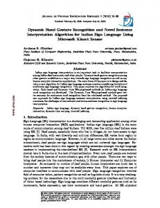
Priority Appreance number
Z, 5
5
Max
Sn
4 F, 3
3
Fig. 7. The best path for LRB model where it starts with S1 and ended with Sn for n=6 states and t=1
J, 2
N, 2
V, 2
2
F, 1
J, 1
1
N, 1
V, 1
Z, 1
0 F
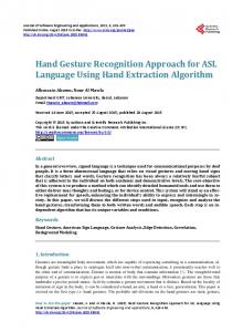
III. EXPERIMENTAL R ESULTS Our method introduced a good results to recognize the gesture alphabet from motion trajectory of a single hand using HMM. The method was implemented in Matlab Language and the outputs are shown in Fig. 8 and Fig. 9. In our experimental results, the alphabet hand gesture was based on 30 video for each alphabet from A to Z which 20 for training and 10 for testing (totally, 520 video for trained gestures and 260 for tested gestures) where the input images were captured by a Bumblebee stereo camera system that has 6 mm focal length for a bout 2 to 5 second at 15 frames per second with 240 × 320 pixels images resolution. Our results are evaluated by the following criteria:
J
N
V
Z
Fig. 9. System output for alphabet Z. The highest priority that is equal to 5 and appearance number equal to 1 is associated to alphabet Z
The testing data is considered as, k=10, for each alphabet. These test data include valid gesture ν and also invalid gesture ν¯ such that; k = νi + ν¯i
i = 1, 2, ..., 26
(9)
where i represent the index of alphabets from A to Z. The valid percentage for each alphabet is calculated by Eq. 10 and the total percentage of all testing data is determined by Eq. 11. ηi =
νi · 100 k