GMPLS Extensions for Supporting Advanced Optical Networking Technologies Didier Colle, Jan Cheyns, Chris Develder, Erik Van Breusegem Ann Ackaert, Mario Pickavet, Piet Demeester Department of Information Technology (INTEC), Gent University - IMEC Sint-Pietersnieuwstraat 41, B-9000 Ghent, Belgium Tel: +32-9/267.35.90, Fax: +32-9/267.35.99, e-mail:
[email protected] Boning Feng, Håkon Lønsethagen, Evi Zouganeli Telenor R&D Snaroyveien 30, N-1331 Fornebu, Norway Tel: +47-95897687, Fax: +47-96210477, e-mail:
[email protected] Juan Fernández-Palacios, Jesús Felipe Lobo TID, Telefonica Emilio Vargas 6, 28043 ,Madrid, Spain Tel: +34 913373923, Fax: +34 913374602, e-mail:
[email protected]: ABSTRACT In response to the need for higher flexibility in optical networks, a Generalised Multi-Protocol Label Switching (GMPLS) protocol suite is currently under standardisation. However, in these standards a Label Switched Path (LSP) hierarchy is defined that only considers circuit-switched optical networks. This paper aims at broadening the scope of this hierarchy to more advanced optical networking technologies. Keywords: GMPLS, LSP hierarchy, wavelength/waveband/fiber-switching, circuit-switching, Optical TimeDivision Multiplexing (OTDM), Optical Packet Switching (OPS). 1. Introduction Since the liberalization of the telecom market, new services are continuously created. Therefore, the service providers have to rely on high-capacity and flexible networks that can be deployed in a cost-efficient way. The need for cost-efficient high-capacity networks pushes the technical progress in optical network techniques. For example, the achievable throughput per fiber keeps growing as more and more wavelength channels at a higher and higher bitrate can be multiplexed onto the same fiber: current state-of-the-art allows transporting at least up to 10 Tbps over a fiber [1]. Considering current research, one day more advanced optical network techniques like Optical Burst/Packet Switching (OBS/OPS) and Optical Time Division Multiplexing (OTDM) might be deployed in commercial networks. The need for cost-efficient flexible networking pushes the development and standardization of appropriate routing and signaling protocols in order to avoid the need for manual interventions of the network operator. Internet Protocol (IP) based solutions have proven to be easy to operate. For example, IP solutions almost always contain features for automatic network discovery and inventory functions. Also their interoperability is an important advantage. Therefore, the current efforts aim at developing and standardizing a distributed control plane relying on IP based protocols and to be applied in optical networks. More precisely, in Multi-Protocol Label Switching (MPLS) capable IP networks it is possible to (signal the) setup of Label Switched Paths (LSP) through the network. A Label Switched Router (LSR) switches the packet based on its label (i.e., similar as in ATM, the LSR translates an incoming -pair into an outgoing -pair) instead of the hop-by-hop routing based on the packet’s destination address. The rationale behind Generalized-MPLS (GMPLS) [2] is that for example a wavelength can perfectly function as a label (instead of for example an integer as the labels in classical MPLS) and thus the signal protocols to setup an LSP are conceptually also applicable to wavelength switched networks. A GMPLS-based control plane controlling a multi-layer/multi-technology network should be capable of identifying the type of the LSP and which LSPs are multiplexed into which other LSPs. For this purpose, an LSP hierarchy has been defined [3]. However, this LSP hierarchy does not consider the above mentioned advanced optical networking technologies (i.e., OTDM and OBS/OPS). This paper aims at extending this LSP hierarchy for those technologies. This work was partly funded by the IST-projects STOLAS and DAVID and the IWT-GBOU project 010058 “Optical Networking and Node Architectures”. D. Colle and E. Van Breusegem would like to thank the IWT for its financial support for their postdoctoral and PhD grants. J. Cheyns and C. Develder are Research Assistants with the Flemish Fund for Scientific Research.
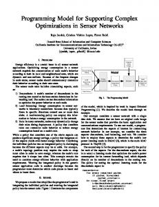
The first part of the paper, i.e. sections 2 and 3, discusses the targeted advanced optical networking technologies more in detail. In a second part of the paper, the current relevant GMPLS-extensions are illustrated first (in section 4) before the extended LSP hierarchy is proposed in section 5. Finally, section 6 summarizes the paper. 2. From Wavelength- To Fiber-Switching Spectral granularity is a first dimension to consider in optical networking. Figure 1 shows that optical nodes can switch wavelengths individually, wavebands (i.e., a bundle of wavelength channels) or complete WDM channels present on the fibers as one single entity. In all cases a space switch matrix actually performs the switching. In the case of wavelength or waveband switching wavelength selective devices are needed at the ingress and/or egress of the switch. As the figure shows, optional wavelength convertors can be provided in the case of wavelength and waveband switching. In the case of fiber-switching no (de)multiplexers or convertors are needed. Having a coarser switching granularity typically means a reduction in equipment size. For example, in case of waveband-switching the (de)multiplexers need less ports (assuming that the fibers carry the same amount of wavelength channels) and no (de)multiplexers at all are needed in case of fiber-switching. However, a coarser switching granularity also implies a possibly reduced capacity usage: for example, in the worst case only one wavelength channel can be needed/be in use between the nodes that terminate an end-to-end waveband connection. Therefore, an optimized network should typically be able to switch multiple granularities. Switchmatrix L1 L2 L3 L4
L1 L2 L3 L4
L1 L2 L3 L4
L1 L2 L3 L4
Wavelength conversion
L1-L2
Switchmatrix
L1-L2
L3-L4
L3-L4
L1-L2
L1-L2
L3-L4
L3-L4
Switchmatrix
Waveband conversion
Figure 1: from left to right wavelength-, waveband- and fiber-switching technologies Note that the above discussion on spectral granularity is independent of the way switching is performed in the time domain. This will be discussed in the next section. 3. From Circuit- To Packet-Switching The second dimension to consider in optical networking is the way multiplexing and switching is done in the time domain. Figure 2 presents the whole scale from optical transparent circuit-switching to optical packetswitching. In optical transparent circuit-switching signals are simply sent from the inlets to the appropriate outlets: any kind of transparent space-switch can suite this purpose (e.g., a slow MEMS-based switch-matrix). By properly configuring these space-switches an end-to-end circuit is realized. These circuits are said to be transparent, in the sense that the switching in the network nodes is completely independent from the content sent through the circuits. In Optical Time Division Multiplexing (OTDM) multiple circuits are multiplexed onto the same incoming/outgoing signal. More precisely, each circuit only exists during one time-slot in a repetitive frame of time-slots. In other words, at the beginning of each time-slot the space switch is reconfigured and the sequence of configurations during the duration of one frame is continuously repeated. It is clear that OTDM is more challenging from a technological point of view: first of all, the switch-matrix should reconfigure sufficiently fast and secondly, a proper synchronization of the signals is of utmost importance. Although the figure might give the impression that frames on different signals should be aligned, this is not necessarily the case (only slot-synchronization is needed). However, due to the lack of optical memory, an OTDM-switch will more than probably not allow storing the data of one time-slot to be inserted in a later time-slot (while this is typically less critical in electrical TDM networks). By having a repetitive frame-structure, each time-slot corresponds to a fixed-bandwidth circuit, with a granularity that is lower than the bitrate of the wavelength. However, in case of Optical Packet- (or Burst-)Switching (OPS) a header accompanying a payload dictates to which traffic flow the payload belongs and thus how it should be routed through the network. Although operating an OPS network in slotted-mode (like in OTDM) might be easier from a technological viewpoint, only the headers belonging to the data in a certain time-slot dictate how the switch matrix has to be configured in that time-slot. The advantage of OPS is that it allows statistical multiplexing: i.e., packets are sent and thus only occupy capacity in the network when there is effectively data to be carried over the network while in silent periods the capacity becomes available to other traffic streams. The drawback of OPS is that the nodes needs additional means for header recognition, rewriting and processing and for contention resolution.
A YOA YO X B Z X B Z MN CMNC
OUT3 OUT2OUT1
X Y Z X Y Z
Process headers and configure matrix accordingly
FRAME FRAME
IN1 IN2 IN3
A BC AB C MNOMNO
OUT3 OUT2OUT1
FRAME FRAME
IN1 IN2 IN3
IN1 IN2 IN3
OUT3 OUT2OUT1
IN1 --> OUT2 IN2 --> OUT3 IN3 --> OUT1
IN1, SLOT1 --> OUT1, SLOT1 IN1, SLOT2 --> OUT2, SLOT2 IN1, SLOT3 --> OUT3, SLOT3 IN2, SLOT1 --> OUT3, SLOT1 IN2, SLOT2 --> OUT3, SLOT2 IN2, SLOT3 --> OUT1, SLOT3 IN3, SLOT1 --> OUT2, SLOT1 IN3, SLOT2 --> OUT1, SLOT2 IN3, SLOT3 --> OUT2, SLOT3
Figure 2: from left to right optical transparent circuit-, OTDM circuit- and optical packet-switching Note that the discussion in this section is independent of the spectral granularity of the switched signals. More precisely, Figure 2 focuses on the switch-matrix and omits any surrounding (de)multiplexers and convertors. Thus the packets drawn in the right part of Figure 2 may actually consists of a payload spread over multiple wavelength channels accompanied by a single header. Considering a multi-layer network, this payload may be disassembled further in packets per wavelength channel. 4. Current GMPLS Routing Protocol Extensions In IP networks the routing protocols allow exchanging information between the routers in order to populate their routing tables. In link-state routing protocols, each router advertises the state of its incident links to all other routers in the network. Each router stores all received Link-State Advertisements (LSAs) in a Link-State Database (LSDB) in order to keep an (almost) up-to-date overview of the complete network topology. Based on this topology information, the routing tables can be calculated: this table keeps track of the next-hop along the shortest path for each destination address (range). The routing tables allow hop-by-hop routing of the packets based on their destination address. In Multi-Protocol Label Switching (MPLS) packets are labeled (e.g., a 20-bit label in a shim-header) at the network ingress and transported through Label Switched Paths (LSPs) through the network. The advantage of label switching is that the core routers should only check on which interface and with what label an incoming packets is received in order to lookup on which interface and with what label the packet should be forwarded. Since routers only negotiate about which labels to use for what traffic flows during the setup of the LSPs, more complex routing/traffic engineering strategies can be adopted: for example, a bundle of disjoint LSPs can be setup from ingress to egress over which the load is evenly distributed. Generalized MPLS (GMPLS) aims at generalizing the label concept: for example, instead of integer, also a wavelength – or color – can serve as label. And thus the existing MPLS protocol suite to setup regular LSPs can easily be modified for setting up e.g. a lightpath through an optical network. In this way, a distributed control plane is created that can be useful in automating the provisioning process or speeding up shared restoration actions. The above discussion on the routing protocol is limited to a single layer network scenario. However, thinking about an IP over WDM network, an LSP can be either a lightpath (i.e., labels are wavelengths) or a regular LSP in the IP layer (labels are integers possibly carried in a shim header). The question is now how to route the latter LSPs, since they have to be routed over a logical network topology formed by the lightpaths or thus the former LSPs. Therefore, from the moment that a LSP has been set up that has to function as a logical link, it will be advertised by means of a link-state packet to all other routers. In order not to mess up the link-state database and to be able to distinguish between different link types the link-state contains a field indicating the multiplexing/switching capability of the advertised link. In such a way, an integrated overview of a multilayer network can be obtained. The IETF is currently working on the extensions to OSPF and IS-IS for GMPLS ([3], [4]), which are based on the proposed Traffic Engineering extensions to these protocols ([5], [6]). In these extensions, the definition of “link” has been extended to include “traffic engineering links” (TE links). In GMPLS, a node that creates and maintains a LSP may announce this LSP as a TE link in the routing advertisements. A switching capability field in the link-state packets the type of the LSP/TE-link. The table below gives an overview of the values defined within the OSPF-TE extensions. Value 1 2 3 4 51 100 150 200
Meaning Packet-Switch Capable-1 Packet-Switch Capable-2 Packet-Switch Capable-3 Packet-Switch Capable-4 Layer-2 Switch Capable Time-Division Multiplex Capable Lambda-Switch Capable Fiber-Switch Capable
Acronym PSC-1 PSC-2 PSC-3 PSC-4 L2SC TDM LSC FSC
5. Extended LSP Hierarchy for Advanced Optical Networking Technologies In the previous section the need for a multiplexing/switching capability field in the Link-State Advertisements (LSAs) to represent multi-layer networks is explained. As shown in the above table an “LSP hierarchy” dictates what LSP type can be multiplexed into another LSP type. The goal of this section is to investigate how the above described LSP hierarchy can be extended to incorporate the advanced optical networking technologies discussed in sections 2 and 3. Figure 3 illustrates a proposal for such an extended LSP hierarchy. The LSP hierarchy currently under consideration in the extensions to the OSPF routing protocol [5] corresponds to what is underlined in this figure. The figure should be interpreted as follows. The arrows indicate how a particular LSP type can be multiplexed into another LSP type. A packet-switched LSP can be multiplexed into a circuit but not vice versa. Note also that not each LSP type needs to be present in each instantiation. For example, one could directly multiplex PSC2 LSPs into e.g. a TDM circuit or in an OPSC-1 LSP (by simply ignoring the PSC-3&4 and L2SC levels). E.g., ethernet
PSC-1
PSC-2
PSC-3
PSC-4
L2SC
OPSC -L-1
OPSC -L-2
OPSC -L-3
OPSC -L-4
OTDM-L
LSC
OPSC -B-1
OPSC -B-2
OPSC -B-3
OPSC -B-4
OTDM-B
BSC
OPSC -F-1
OPSC -F-2
OPSC -F-3
OPSC -F-4
OTDM-F
FSC
Packets TDM circuits
TDM
Electrical level Wave-Length (Lambda) level
Wave-Length (Lambda) level Wave-Band level Wave-Band level Fibre level
TDM circuits Transparent circuits
Figure 3: GMPLS LSP hierarchy extension for advanced optical networking technologies The objective in our proposal was to keep the original philosophy as much as possible. From what is underlined in the figure the currently defined LSP hierarchy already incorporated the spectral granularity dimension described in section 2. The other dimension discussed in section 3, i.e. how switching and multiplexing is performed in the time-domain – from circuits to packets –, has been added in Figure 3. As may be clear from the statements at the end of both sections 2 and 3, both dimensions are orthogonal to each other: this is also reflected in our proposal of Figure 3. The above proposal allows for many combinations, each of them reflecting another multi-layer network scenario. For example, one can think about a long-haul network interconnecting geographically separated network segments. These network segments can form an end-to-end OPSC-L network, while the long-haul network aggregates the traffic flows between the network segments into high-capacity OTDM-B circuits. Protection may be realized in an underlying FSC network layer. Summarized, this would mean that this example corresponds to an OPSC-L/OTDM-B/FSC multi-layer network. Other scenarios will be illustrated during the presentation. 6. Summary In this paper, an overview was given of different advanced optical networking technologies. It seems that they can be categorized by means of two dimensions that are orthogonal to each other. This orthogonality has been reflected in our proposal for extending the currently defined LSP hierarchy, in order to allow applying GMPLS in network scenarios based on the above mentioned advanced optical network technologies. REFERENCES [1] [2] [3] [4] [5] [6]
The IST-project OPTIMIST: www.ist-optimist.org E. Mannie, “Generalized Multi-Protocol Label Switching Architecture”, April 2003 (work in progress), http://www.ietf.org/internet-drafts/draft-ietf-ccamp-gmpls-architecture-06.txt K. Kompella and Y. Rekhter, “OSPF Extensions in Support of Generalized MPLS”, December 2002 (work in progress), http://www.ietf.org/internet-drafts/draft-ietf-ccamp-ospf-gmpls-extensions-09.txt K. Kompella and Y. Rekhter, “IS-IS Extensions in Support of Generalized MPLS”, December 2002 (work in progress), http://www.ietf.org/internet-drafts/draft-ietf-isis-gmpls-extensions-16.txt D. Katz et al, “Traffic Engineering Extensions to OSPF”, October 2002, Internet Draft (work in progress), http://www.ietf.org/internet-drafts/draft-katz-yeung-ospf-traffic-09.txt H. Smit and T. Li, “IS-IS extensions for Traffic Engineering”, December 2002, Internet Draft (work in progress), http://www.ietf.org/internet-drafts/draft-ietf-isis-traffic-04.txt