Recent Advances in Systems
Graphical Programming for Control and Instrumentation Curses Jorge M. Jaimes Ponce, Jesús U. Liceaga C., Irma I. Siller A. and Roberto A. Alcántara R.
microcontroller for which already exist many LabVIEW applications allowing the substitution of the data acquisition hardware. A final option is the use of the National Instruments software, from which the modulus for USB data acquisition are the cheapest and sufficient enough for many applications.
Abstract—Normally commercial software and equipment for control and instrumentation lectureships are rather expensive for public universities reducing student’s opportunities to develop important professional skills. However, different technologies have emerged which considerably reduce the costs of this learning process without using real industrial components. This paper tackles the issue of the study of control engineering and instrumentation from three different approaches applying the LabVIEW graphical programming language. The first one, based exclusively in simulation; the second, is by means of the use of Arduino; and the third, is by applying the commercial hardware from National Instrument. These strategies are well within public universities budgets.
Keywords—Graphical
Programming,
Process
II. APPROACHES GENERAL DESCRIPTION A. Simulation of Process using LabVIEW One of the most important aspects of the use of LabVIEW for process simulation is that it is possible to implement the mathematical model of a process in a SubVI [2], such that its dynamical behavior can be simulated under different operating conditions or several parametrical configurations. Moreover, this model simulation can be used for control purposes using ON/OFF or PID controllers. In the same way, a sensor can be also simulated. With the use of several of these VI’s it is possible to simulate more complex systems which can include real industrial conditions for voltages, currents, pressures and fluxes, making the simulations more realistic.
Simulation,
Arduino.
I. INTRODUCTION
T
HEACHING control engineering or instrumentation using industrial devices or components may result highly costly even with the use of equipment specifically designed for educational purposes. When the lack of economic resources is a reality, a common practice to overcome the deficiency of industrial components is the use of digital simulations or the development of own software, mainly based on C language, Visual Basic, etc. Although, the development of software is an excellent alternative it may takes a considerably long time. A second option is to acquire a LabVIEW license, [1]. This software can be used for teaching purposes by creating software applications. For instance, the development of Virtual Instruments (VI) applications to simulate industrial devices such as fluid containers, pressurized tanks, furnaces, engines, etc. or temperature, flux and pressure sensors. Another alternative is to use commercial systems based on microcontrollers like Arduino. Arduino is a very economic
B. Control and Instrumentation of Process using LabVIEW and Arduino Arduino has become a very popular and powerful system despite its limitations in speed and capacities for data processing compared to other microcontrollers, [3]. Nonetheless, it represents a low-cost helpful option due to all the support available to create interfaces with LabView. The A/D converters, digital E/S and PWM generation make Arduino a good device for the control and instrumentation for applications not demanding high capabilities for data processing. Several tools or functions are available for serial connections and A/D – D/A converters linked to the generation of PWM signals, Figure 1. These functions can be used to implement different and interesting projects.
J. M. Jaimes-Ponce is with the Electronic Department of the UAMAzcapotzalco, Av. San Pablo 180 C.P. 02200, México (e-mail:
[email protected]). J. U. Liceaga-Castro is with the Electronic Department of the UAMAzcapotzalco, Av. San Pablo 180 C.P. 02200, México (phone: 52-5553189041 ; e-mail:
[email protected]). I. I. Siller-Alcalá is with the Electronic Department of the UAMAzcapotzalco, Av. San Pablo 180 C.P. 02200, México (e-mail:
[email protected]). R. A. Alcántara-Ramírez is with the Electronic Department of the UAMAzcapotzalco, Av. San Pablo 180 C.P. 02200, México (e-mail:
[email protected]).
ISBN: 978-1-61804-321-4
213
Recent Advances in Systems
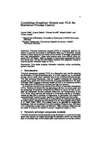
Fig. 4 PSV-5 proportional valve
III. APPROACHES DEVELOPMENT
Fig. 1 Arduinos tools for LabVIEW
A. Simulation using Graphical Programming The aim of creating SubVIs for the simulation of several industrial devices is to induce the students to the analysis of the dynamical models and data sheets of such devices. This will enable them to face real industrial conditions. For example, by consulting the data sheet of a humidity sensor the students must deduce that this variable depends on the environments temperature or with the dynamical model of a level system it must be also concluded that the liquids flow depends on the density and level of the liquid. By analyzing the data sheet of the temperature sensor PT100 it can be assumed that it has linear behavior, [4]. Based on this characteristic it can be also determine how to condition its output signal using electronic components to generate measurements within industrial standards such as 0 to 5 volts or 4 to 20 mA. The SubVI of a PT100, in Figures 5 and 6, show the output voltage, proportional to the resistance, assuming a 1 mA input current.
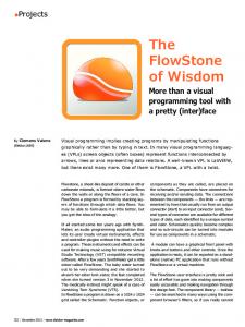
C. Control and Instrumentation of Process using LabVIEW A third relatively economic option is to use National Instrument Data Acquisition Boards (NIADQ). In the market of the process instrumentation and control there are several data acquisition boards for general purposes with USB communication. In this case a real process or at least a prototype is required. A real industrial process may be really expensive; however, it is possible to construct a prototype at a considerably lower cost than a real process. The prototype of a Level process, depicted in Figure 2, consists of an acrylic tank of 50cm deep, a submerge water pump, a MPX2010DP pressure sensor -Figure 3- to indirectly measure the liquids level, and the PSV-5 proportional valve shown in Figure 3.
Fig. 5 SubVI frontal panel of the PT100
Fig. 2 Prototype of a Level process
Fig. 3 MPX2010DP pressure sensor
Fig. 6 PT100 SubVI program ISBN: 978-1-61804-321-4
214
Recent Advances in Systems
With the SubVI of the PT100 it is possible to use it, as a specific function, in the implementation of a block diagram of some process which requires sensing the temperature, Figure 7.
Fig. 10 Control Level System VI with two tanks
Fig. 7 Application of the PT100 SubVI
Other example consists in the implementation or simulation -Figure 8 and 9- of differential equations describing the dynamical behavior of a level system with output flow.
Fig. 11 Control Level System VI block diagram with two tanks
B. LabVIEW and Arduino As mentioned above, Arduino includes a connecting or communication toolbox just like a typical USB data acquisition boards has, Figure 12. Obviously, Arduino doesn’t have the resolution of industrial data acquisition boards; nevertheless, for some applications it is a powerful and economic alternative.
Fig. 8 Level System simulation
Fig. 9 Block diagram of a Level System model Fig. 12 Arduino communication toolbox
Similar to the previous example, with the SubVI of the Level System it is possible to develop a VI to simulate a Level Control System which can include several interconnected tanks, Figures 10 and 11.
ISBN: 978-1-61804-321-4
If a real process or a prototype is not available it is possible to emulate some simple processes using RC circuits. For example, to emulate a Level System with output flow a parallel RC circuit can be used as shown in Figure 13. In this case
215
Recent Advances in Systems
A relatively more complex application is the emulation of a Level system in which a largest tank is connected in series to two smaller tanks. This means that the largest tank feeds the two smaller tanks.
when switch S1 is off the capacitor C1 will discharge, and when switch S1 is on the capacitor will charge.
Fig. 16 Block diagram of the Level Control System with hysteresis of two tanks
Fig. 13 RC Simulation of a Level System with output flow
Figures 17 and 18 show the diagram and the actual RC circuit that emulate the three tanks level system.
Figures 14 and 15 show the charge and discharge of the capacitor showing a similar response to the level system with output flow. This VI displays the control panel from which it is possible to change the level of the liquid in the tank emulating the real tank.
Fig. 17 Diagram of the RC circuit to emulate the three tanks system
Fig. 14 VI using a RC circuit and Arduino
Fig. 15 VI using a RC circuit and Arduino with different control limits and hysteresis
Fig. 18 Actual diagram of the RC circuit to emulate the three tanks system
The VI shown in Figure 16 is identical to anyone designed for a commercial data acquisition board; it only requires to substitute the Arduinos tools of data acquisition and signal generation for the specific functions of the commercial data board.
The control panel of the three tank level system is shown in figure 19.
ISBN: 978-1-61804-321-4
216
Recent Advances in Systems
Fig. 19 Frontal Panel for the three tanks system
Finally in Figures 20, 21 and 22 three responses of the control of the level system emulated by the RC circuit are shown. In this case, the controller is based on the classical PID with a block diagram depicted in Figure 23.
Fig. 22 Level System response with a PID controller (Kp= 1, Ki = 0.1 and Kd = 0.5.)
Fig. 23 Block Diagram of the PID controller Fig. 20. Level System response with a PID controller
C. Instrumentation and Control using LabVIEW and the NI USB-6009 Data Acquisition Board
(Kp = 1.5, Ki = 0.05 and Kd = 0.05.)
The electronic circuits and prototypes described in the previous sections can be controlled using the data acquisition board NI USB-6009 from National Instrument getting exactly the same results. The only difference is the exchange of the function blocks for those specifically designed to the USB6009. For the level control of the single tank system shown in Figure 2 the PID controller programmed in the Formula Node to control the RC circuit tank emulator was used. It only requires a retuning using the actual parameters of the process. Once the system or process has been characterized the PID parameters can be tuned in the Formula Node getting the closed loop responses shown in Figures 25-28. Fig. 21 Level System response with a PID controller (Kp= 1.5, Ki = 0.1 and Kd = 0.5.)
ISBN: 978-1-61804-321-4
217
Recent Advances in Systems
practice and theory is a must. On the other hand, to get access to costly real industrial process is not always possible. In this sense the use of Arduinos represent a good alternative especially with the development of new economical sensors that can be used to construct non expensive prototypes capable to emulate real industrial processes. This has also been possible due to possibilities that LabVIEW and Arduino offer. With the use of commercial of Data Acquisition Boards the possibilities of better experiments increase.
Fig. 25 Level System response with a PID controller (Kp = 5, Ki = 0.1 and Kd = 0.05.)
REFERENCES [1] [2] [3] [4]
Fig. 26 Level System response with a PID controller (Kp = 5, Ki = 0.25 and Kd = 0.1.)
Fig. 27 Level System response with a PID controller (Kp = 5, Ki = 0.25, Kd = 0.1 and Set Point = 20.)
Fig. 28 Level System response with a PID controller (Kp = 5, Ki = 0.025 and Kd = 0.01.)
IV. CONCLUSION In this paper three different teaching approaches that help to overcome the lack of real industrial process or components in control and instrumentation lectureships are presented. This approaches aid in the comprehension and understanding of these complex topics that otherwise must be treated in a pure theoretical context. We consider that equilibrium between ISBN: 978-1-61804-321-4
218
Ronald W. Larsen, “LabVIEW for Engineers”, E-SOURCE, PrenticeHall, 2011. Peater A. Blume, “The LabVIEW Style Book”, Prentice Hall, 2009. Don Wilcher, “Learn Electronics with Arduino”, Technology in Action, 2013. Lawrence T. Illage, Ronald A. Roher, Chandramouli Visweswariah, “Electronic Circuits and Systems Simulation Methods”, McGraw-Hill, Inc., 1995.


![[PDF] LabVIEW for Everyone: Graphical Programming Made Easy and ...](https://m.moam.info/img/260x300/pdf-labview-for-everyone-graphical-programming-mad_6476f223097c474b228b4633.jpg)