improve the ability to detect watermarks in image and video data. It is well known that ... Data/Add. RegBus. PIPEFlow Right 32bit. Global PIPEFlow Bus (Global) 32bit ..... Stirmark. [Online]. http://www.cl.cam.ac.uk/ fapp2/watermarking/stirmark/.
Hardware Efficient Algorithm for Image Registration of Real-time Video and Image Data Wim J. C. Melis1∗, Peter Y. K. Cheung1 , Wayne Luk2 1
Department of Electrical & Electronic Engineering Imperial College, Exhibition Road London SW7 2BT, England 2
Department of Computing, Imperial College 180 Queen’s Gate, London SW7 2BZ, England
Abstract This paper is concerned with image registration as applied to video sequences that have been subjected to geometric distortions. It describes the development of two computationally efficient algorithms to restore broadcast quality video sequences using image registration techniques. The image registration technique is based on motion vectors and found to be successful in restoring the video sequence for either affine transformations or the more general perspective transformations. It is shown that both algorithms can accurately restore the video data. The algorithms can efficiently be implemented on a reconfigurable computer system for real-time video restoration.
1 Introduction A large number of watermarking algorithms have been presented [20, 21]. However in developing these algorithms there is often the trade off between improving the algorithm so it allows including more data in a secure way and making the algorithm more robust against distortions. Some algorithms present a combination of registration and specially designed watermarking algorithms to achieve higher robustness [17]. This paper is concerned with detecting the applied distortion and registering the image to improve the watermark detection, independent of the used algorithm. Reconfigurable computing platforms are well known to cope with the high data throughput and computational demand related to real-time video image processing. Therefore there are a large number of successful implementations of image and video applications [9, 12, 18] on this type of platforms. The target platform for this application was developed in cooperation between Imperial College and Sony Broadcast and is called SONIC [6, 7]. Its architecture has been specialised for broadcast video editing, manipulation and processing. The presented algorithm is developed for efficient implementation on this type of reconfigurable systems to allow for real-time performance. Image registration is in this work defined as the restoration of an image or a video sequence that is subjected to some form of geometric distortion. Although this techniques does know a large amount of applications, in this paper it is used to improve the ability to detect watermarks in image and video data. It is well known that most watermarking techniques are not robust to 2-Dimensional (2D) or 3-Dimensional (3D) geometric distortions such as rotation, shear, shift or perspective transformation [4]. A number of approaches to restore the image have already been proposed [11, 10]. However they employ algorithms that are suited to a general-purpose computer with floating point unit. Other approaches focus on the synchronisation between the distorted video and original video [2] or estimate the distortion making use of feature points [3]. The authors of this paper present two computational efficient algorithm which can be used for either affine or the more general perspective transformation based distortions.
Custom Interface (SDI) Virtex Device XCV1000E
RegBus
PIPE 16
PIPE 2
PIPEFlow OUT
PIPE 1
PIPEFlow IN
LBC (Local BusController) XCV300
PE REG MemData
PE
PIPE Bus - 64bit Address/Data and 2 bit control
Global PipeFlow Bus 32bit + 2bit Ctrl
Data/Add
2MB SRAM 2MB SRAM
Data/Add
2MB SRAM 2MB SRAM
PR PCI
PipeFlow Chain 32bit + 2bit Ctrl PIPEFlow Left 32bit
PCI Bus 64bit 66MHz
PIPEFlow Right 32bit
Global PIPEFlow Bus (Global) 32bit PIPE Bus (Global) 64bit
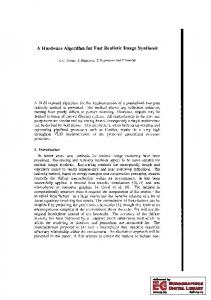
Figure 1. Simplified Block Diagram of the UltraSONIC architecture
The organisation of the paper is as follows: after a brief description of the target architecture, the image registration problem for watermarked data is explained in Section 3. The algorithms to solve this problem are presented in the next sections, after which their implementation is shortly described in Section 5. The results of the algorithms are presented in Section 6, which is followed by the Conclusion (Section 7).
2 The SONIC Architecture The SONIC reconfigurable computing platform [6, 7] is designed to cope with the high data throughput and deliver the computational power needed for real-time video applications. A simplified block diagram of the latest implementation is shown in Figure 1. The design consists of Plug-In Processing Elements (PIPEs) which are interconnected by a set of buses. The platform exploits as well temporal as spatial parallelism in video processing algorithms. It also facilitates design reuse and supports the software plug-in methodology. The PIPEs consist of three parts: PIPE Engine (PE), PIPE Router (PR) and PIPE Memory (PM). The PE handles the computation, while the PM is meant to buffer video data as a way to reduce the bus traffic. The PR handles image data movement and formatting. The separation of PR and PE allows for computation functions to be implemented independently from the dataflow. The settings for the PR are controlled by the users application through a set of well-defined SONIC Application Programming Interface (API) routines. The SONIC architecture knows already two implementations, of which the first one was based around a Flex10K100 for the PE and a Flex10K50 device for the PR. The latest implementation, UltraSONIC [8], is based around Virtex XCV 1000E devices implementing both the PE and PR.
3 The Image Registration Problem in Watermarking Watermarking is the insertion of information (watermark data) into host data without perceptible corruption. This embedding of data can be done for several reasons, including copyright protection and metadata embedding. Especially in the first case, the embedded data should only be accessible by authorised parties which implies a requirement for a certain level of robustness against attacks. Applying geometric distortions to the watermarked image and video data is only one way of attacking the watermark data. For example, most watermark extraction and detection algorithms do not tolerate 2D and 3D geometric transformations. To overcome such attack, the corrupted image can be passed through an image registration step before watermark detection is performed. Furthermore, the watermark algorithm can either be blind or non-blind. In blind watermarking, the original image 2
Watermarked image (W)
W a t e r m a r k i n g
Original image (O)
Distortion T
Adjust
Inverse -1 Te
Estimate Te Corrupted image (C)
Restored image (R)
Figure 2. An Approach to Image Registration
is not required to extract or detect the watermark. In contrast, non-blind watermarking assumes that the original image is available. A possible image registration approach to non-blind watermarking is shown in 2. The watermarked video sequence W is subjected to a geometric distortion function T which produces a corrupted video sequence C with the watermark information corrupted. Making use of the original video sequence O, an estimate of the distortion Te is made. From this estimate, an inverse distortion function Te−1 is derived and used to restore the corrupted video to improve the possibility of extracting or detecting the watermark. This restored video sequence R can then be further compared with the original sequence O to improve the estimated distortion function in a recursive manner. Due to the high data throughput of a broadcast quality video sequence, it is reasonable to assume that the distortion is globally applied. Furthermore, any type of linear distortion such as: rotation, shear, shift and scaling can be formulated as an affine transformation using Equation (1). An affine transformation is actually a special case of the more general perspective transformation as presented in Equation (2) (based on [19]). µ 00 ¶ µ ¶µ ¶ µ ¶ x a b x e = + (1) y 00 c d y f a c g ¡ 0 ¢ ¡ ¢ x y0 z0 = x y z b d h (2) e f i In each of the Equations (1, 2), (x, y)/(x, y, z) represent the position in the original 2D image (where z = 1). The new 2D position of the pixel is represented by (x00 , y 00 ), whereas (x0 , y 0 , z 0 ) is the position in the 3D space which will need to be converted. The parameters sets (a, b, . . . , f ) or (a, b, . . . , i) specify the distortion function. These parameters have to be estimated and an inverse function Te−1 can then be used to restore the image. The affine transformation is a special case of the perspective transformation where z 0 = z = i = 1 and g = h = 0 in Equation (2).
3
Figure 3. Motion Vector Estimation a) & b) Division into blocks and determined motion vector; c) Motion vector map for perspective distortion of similar type as shown in b).
4 The Solution The approach in solving the image registration problem is based on localised motion vectors [5]. A frame from the original video sequence is divided into square blocks. For each reference block a motion vector is computed by finding the best match in the correspondent frame from the corrupted video, see Figure 3 a) & b). Since motion vectors are themselves linear displacements, their usefulness in the current application depends on two factors: 1) the distortion is translational; 2) the distortion is not translational but is sufficiently small that it can be approximated as translational at the block level. The assumption that the distortion is small is not unreasonable, otherwise its effect would become noticeable. In our application, a typical value used for the block size (in pixels) is 16x16, and a search area of ±20 pixels is normally sufficient for the expected distortions. This results in a motion vector map, of which an example for a perspective distortion of similar type to the one shown in Figure 3 b) is shown in Figure 3 c).
4.1 Affine Transform In order to find the relationship between a motion vector (u, v), the coordinate of the centre of an image block (x, y) and the affine transform distortion parameters (a, b, c, d, e, f ), Equation (1) can be rearranged to: µ
u v
µ =
a−1 b c d−1
¶µ
x y
µ +
e f
¶ (3)
which is based on the definition of the motion vectors being: µ
u v
µ =
x00 − x y 00 − y
This Equation (3) can then be separated into two orthogonal components one for x- and one for the y-direction: a−1 ¡ ¢ u= x y 1 b e c ¡ ¢ v = x y 1 d−1 f
(4)
(5)
(6)
In theory only three motion vectors are necessary to compute the six distortion parameters. However, Equation (5) and (6) are exact only for the case where the distortion is a translation by an integer number of pixels in the x and y directions. It is 4
an approximation for all other cases of affine transform distortion. Therefore, to obtain the best estimates for (a, b, c, d, e, f ), all motion vector information can be combined as: uaff = Aaff paff
(7)
vaff = Aaff qaff
(8)
where, uaff =
u1 u2 .. .
, vaff =
uM
x1 y1 1 x2 y2 1 Aaff = . .. .. .. . . xM yM 1 a−1 = b , qaff = e
paff
v1 v2 .. .
(9)
vM
(10)
c d−1 f
(11)
Equation (7) and (8) represent an over-determined system with unknown paff and qaff , for which the least square solutions can be obtained by:
p ˆ aff
q ˆaff
a ˆ−1 = ˆb = Aaff −1 uaff eˆ cˆ = dˆ − 1 = Aaff −1 vaff fˆ
(12)
(13)
ˆ eˆ, fˆ) are the least square solutions for the six parameters of the where Aaff −1 is the pseudo-inverse of Aaff and (ˆ a, ˆb, cˆ, d, distortion function. Note that Aaff is a constant matrix with its values (x1 , x2 , . . . , xM ) and (y1 , y2 , . . . , yM ) given by the centre coordinates of the reference windows used to compute the motion vectors. Therefore the pseudo-inverse Aaff −1 only needs to be computed once for each reference window size. ˆ eˆ, fˆ) are found, image registration is accomplished by applying the inverse distortion function to the Once (ˆ a, ˆb, cˆ, d, corrupted video according to: µ
x ˆ yˆ
µ =
a ˆ ˆb cˆ dˆ
¶−1 µ
x00 − eˆ y 00 − fˆ
¶ (14)
where (ˆ x, yˆ) and (x00 , y 00 ) are the pixel coordinates in the restored and corrupted video frames respectively. In practical applications, Equation (14) is not applied directly since mapping each pixel in the corrupted frame to a restored frame will in general leave many pixels unfilled. Therefore the restoration process is conducted in a reverse manner: for each pixel in the restored frame, the pixel coordinate in the corrupted frame is computed in order to reverse the distortion process. Linear interpolation is further employed to produce a smooth image. Although this method can efficiently handle affine transformations, it is also possible that a small perspective transformation is applied, which requires a slightly different way to calculate the parameters.
5
4.2 Perspective Transform Since perspective transforms are actually 3-Dimensional transformations (see Equation (2)), but only 2-Dimensional images are considered, a conversion is necessary. Combined with the fact that i and z can be set to one (as described in [19]) this leads to: x00 =
ax + by + e x0 = , 0 z gx + hy + 1
y 00 =
y0 cx + dy + f = 0 z gx + hy + 1
(15)
in which x00 and y 00 are the coordinates in the new 2D image. Rearranging these equations to the following format will make further usage easier: x00 = ax + by + e − gxx00 − hyx00 ,
y 00 = cx + dy + f − gxy 00 − hyy 00
(16)
These equations give a relation between the values x and y, for which again the centre of the block is taken, the parameters and the new positions (x00 , y 00 ). The new positions are again not known, but can be derived from the motion vectors (u, v) according to the first line of Equation 4. Making use of these equations, the values for x00 and y 00 can be calculated and substituted in Equation (16), which allows the construction of a matrix representation with only the parameters (a, b, c, d, e, f, g, h) as unknown. Although in theory four sets of motion vectors and their corresponding block coordinates are sufficient to determine the parameters, it is again better to use all the motion vectors and block coordinates that are available. This results in Equation (17) similarly exploiting the least square method to reduce the effect of the less reliable motion vector values on the overall parameter value estimation.
x1 .. . xn 0 . ..
y1 .. .
1 .. .
0 .. .
0 .. .
0 .. .
−x1 x001 .. .
yn 0 .. .
1 0 .. .
0 x1 .. .
0 y1 .. .
0 1 .. .
−xn x00n −x1 y100 .. .
0
0
0
xn
yn
1
−xn yn00
00 a −y1 x001 x1 b .. .. e . . 00 00 xn −yn xn c = Apersp ppersp = 00 y100 −y1 y1 d f . .. . . . g 00 −yn yn yn00 h
(17)
The least square solution can be found using: pˆpersp = A−1 persp
¡
x001
. . . x00n
y100
...
yn00
¢T
(18)
ˆpersp is the matrix containing the least square solutions of the distortion where A−1 persp is the pseudo inverse of Apersp and p function parameters. As matrix Apersp is in this case dependent on (x00i , yi00 ), which in turn depends on the motion vectors (ui , vi ), the pseudo inverse has to be calculated for each new set of motion vectors before the parameters can be determined. Once the parameter values are found, they can be used to perform the image registration making use of the reverse mapping technique, by applying the following equation: ¡
x ˆ
yˆ zˆ
¢
=
¡
x0
y0
z0
¢
a ˆ cˆ ˆb dˆ eˆ fˆ
−1 gˆ ˆ h 1
(19)
Since zˆ is known to be 1, z 0 can be calculated by substituting Equation (15) into Equation (19) at a known coordinate (x00 , y 00 ). Once z 0 is found, (ˆ x, yˆ) can be solved using Equation (15) and Equation (19). Similar to the registration for the affine case, linear interpolation can further be used to produce a smooth image.
5 Implementation The implementation of the image registration system requires two parts to be implemented on HW to achieve real time performance, these are: 1) motion vectors calculation, and 2) image registration. The parameter calculation can easily
6
Detected angle for using the two algorithms (search size = 20).
Results for centre of rotation.
5
Distance fromdetected centre point to centre of image (pixels).
500
4.5
Detected angle of rotation (°).
4
3.5
3
2.5
2
1.5 Legend Affine method Perspective method
1
0.5
0
0.5
1
1.5
2
2.5
3
3.5
4
4.5
300
200
100
0
-100
-200
5
-400
b)
Applied angle of rotation (°).
Legend: Affine method Perspective method
-300
-500 -500
0
a)
400
-400
-300
-200
-100
0
100
200
300
400
500
Distance from used centre point to centre of image (pixels).
Figure 4. Accuracy after Registration for Rotation Distortion comparing both algorithms
be performed in software since this is only required once per frame. It is also one of the main differences between both algorithms, the other change required is the actual image registration. Many full-search motion vector estimation architectures have been proposed. Our implementation is adapted from a design proposed by [13]. Generally this algorithm has high computational and data flow demands. Therefore it comes to minimizing the data flow in such a way that all data are read only once from the external memory. This can be achieved with extensive data buffering. Implementation of determining the parameters according to Equation (12) and (18) is relatively straightforward. When only an affine transformation is applied then A−1 af f can be precalculated. In case of a perspective distortion, this cannot be −1 done since Apersp is dependent on the motion vectors themselves. Once the parameters (a, b, . . . , f ) or (a, b, . . . , h) are determined they can be passed on to the image registration component. Due to the use of the reverse mapping combined with the linear interpolation (which uses 4 pixels) and the required real time performance the data flow demands are again large. Therefore it is again essential to exploit on-chip data buffering. The registration algorithm is again slightly different depending on whether the full perspective or only affine transformation is performed. However since the latter is a special case of the former, only one implementation is essentially required, and can be adapted according to the requirements.
6 Results and Evaluation In order to determine the accuracy of the image registration algorithms, the entire algorithm is implemented in Matlab. This implementation is then applied to distorted watermarked images. The watermarked images are distorted either by a watermark attack program Stirmark [14, 15, 16] or by a transform program written in Matlab. The first part of this result section investigates the accuracy of both algorithms for a rotational transformation. Further accuracy results are then presented for other transformations, including perspective. After which the registration capabilities for watermarked data are presented.
6.1 Accuracy Measurement Figure 4 indicates the accuracy of detecting the angle and centre point for a rotational distortion. Perfect restoration occurs if the solution falls on the 45◦ line. It can be noticed that both methods have approximately the same accuracy close to this 45◦ line. Beyond rotational angles of 3.5◦ a larger search size of ±40 pixels provides much better results. The reason for the inaccurate detection especially for larger angles of rotation is related to the fact that for larger rotations the detection of a correct motion vector becomes harder since the block to match has rotated in the distorted image, therefore the motion vector estimation is not highly accurate. If the search area increases then it also becomes more likely that a false positive is detected, resulting in inaccurate motion vectors and parameters. 7
Rail Boat
Rotation
Boat
Shift
Rail
Boat
Shear
Rail
Table 1. Accuracy for Estimating Parameters of Different Types of Distortions a
b
c
d
e
f
g
h
Applied Detected Applied (1) Detected Applied Detected Applied Detected
1 1.00 1.00 1.00 1.00 1.00 1.00 1.00
0.01 0.01 0.05 0.05 0.05 0.05 0.01 0.01
0.01 0.01 0.05 0.05 0.05 0.05 0.01 0.01
1 1.00 1.00 1.00 1.00 1.00 1.00 1.00
16.00 16.05 -18.00 -17.29 0.00 0.03 2.88 2.96
8.00 7.98 -14.40 -13.56 0.00 -0.05 -3.60 -3.59
2.30E-06 2.09E-06 3.30E-08 2.14E-08
6.00E-07 1.47E-07 1.60E-08 -3.06E-07
Applied Detected Applied (2) Detected Applied Detected Applied Detected
1.00 1.00 1.00 1.00 1.00 1.00 1.00 1.00
0.00 0.00 0.00 0.05 0.00 0.00 0.00 0.00
0.00 0.00 0.00 0.05 0.00 0.00 0.00 0.00
1.00 1.00 1.00 1.00 1.00 1.00 1.00 1.00
2.00 2.01 -15.00 -15.00 3.00 3.00 -6.00 -6.00
0.00 -0.01 3.00 3.00 0.00 -0.01 9.00 9.00
5.80E-09 4.78E-16 8.00E-08 9.65E-16
1.46E-09 -7.55E-16 4.60E-08 -4.32E-16
Applied Detected Applied (3) Detected Applied Detected Applied Detected
1.00 1.00 1.00 1.00 0.99 0.99 1.00 1.00
-0.01 -0.01 0.01 0.01 0.01 0.01 0.01 0.01
0.01 0.01 -0.01 -0.01 -0.01 -0.01 -0.01 -0.01
1.00 1.00 1.00 1.00 0.99 0.99 1.00 1.00
-2.87 -2.90 3.97 3.84 3.97 4.03 1.76 1.67
3.07 3.03 -5.86 -5.93 -5.86 -5.87 -4.36 -4.33
5.50E-09 2.33E-08 4.50E-08 -1.09E-07
8.90E-10 -1.86E-07 3.90E-07 2.19E-07
Figure 4 b) is a plot of the distance of the estimated centre of rotation from the mid-point of the image against the actual distance for a particular angle of rotation using the two different methods. Again the estimated centre lies almost on the perfect solution line at 45◦ . Table 1 shows the accuracy of both algorithms on shift, shear and rotation distortions applied to two images. The results of the affine method can be noticed by the fact that there is no entry for the g and h parameter. In case a perspective transform is applied, then the parameters specific to this perspective transformation are chosen rather small, since any large value gives a very significant modification to the image. These type of transforms would never be applied since they would be too noticeable to the person watching the distorted image. It can be noticed that in general the applied distortion is detected with a rather high accuracy. The small values, related to the perspective distortion (g and h) are often detected with less accuracy which is partly related to the values being very small.
6.2 Registration of Watermarked Images Although the inaccuracy of some of these detected parameters is not optimal, the main goal is to effectively register the image to allow watermark detection. Whether a watermark is detected or not is based on a figure of merit known as sim value (or similarity value). A sim value of 10 or above indicates a watermark has been detected. A sim value below 10 indicates that the registration algorithm has not managed to restore the corrupted image in order for the watermark to be detected. As can be seen from Tables 2 which contains data for the affine registration algorithm and Table 3 containing data for the perspective registration algorithm, the sim valuesof all tested images are well above the threshold of 10.
7 Conclusions Two algorithms, based around motion vectors, to solve the problem of image registration for watermarked video are presented. It is shown they are sufficiently general to handle all global distortions based on affine and/or perspective transformations. The method of calculating the motion vectors and performing the registration can also be applied recursively for 8
Table 2. Results of Watermark Detection after Registration using the affine method Source
Applied Transformation
Sim-value after registration
Football Icehockey Doll Pink
Diagonal shift and 1 degree rotation clockwise Rotation of 1.3 degree anti-clockwise Scaling of 104 % Diagonal shift and 0.4 degree rotation clockwise Rotation of 0.6 degree anti-clockwise, followed by crop and diagonal shift, followed by 0.3 degree rotation anti-clockwise and crop Enlarging the image by 4%
28.2 31.5 67.3 39.8
Yatch Mobile
23.6 29.3
Table 3. Results of Watermark Detection after Registration using the perspective method Source
Applied Transformation
Sim-value after registration
Tree Basket Rail Boat Susie
Pure perspective transformation (only g and h) Pure affine transformation (g and h = 0) Transformation with parameters of Table 1(1) Transformation with parameters of Table 1(2) Transformation with parameters of Table 1(3)
37.9 82.7 30.6 126.1 100.2
improved results. The hardware implementation of the algorithm allows real-time restoration of the watermarked video data and enables subsequent watermark detection. The hardware implementation minimizes the dataflow by careful on-chip data buffering. Real-time performance is achieved through extensive pipelining and parallelism. Currently the algorithm only supports global linear affine/perspective distortions. The next step is to extend the algorithm to handle distortions that are spatial-variant. This should be possible by dividing the video frame into smaller regions. Provided that the distortion within each region can be approximated by an affine/perspective transformation, the algorithm described here should be effective. Finally the possibility of using this algorithm for applications other than watermarking will be investigated. There are many real-time applications, such as video compression, that involve the calculation of motion vectors, and they can benefit from this algorithm and its implementation on SONIC.
Acknowledgements The authors would like to thank Jason Pelly, John Stone, Simon Haynes and Henry Epsom from Sony Broadcast and Professional Research Labs for their help and support. We are particularly grateful for Jason’s help in verifying our results and the many suggestions he made to improve the paper. We would also like to thank Mike Brookes for his suggestions.
References [1] G. L. Brown, “A Survey of Image Registration Techniques,” ACM Computing Surveys, Vol. 24 , No. 4, 1992, pp. 325-376. [2] H. Cheng and M.A. Isnardi, ”Spatial temporal and histogram video registration for digital watermark detection,” in: Proc. International Conference on Image Processing, ICIP 2003, 14-17 Sept. 2003, vol. 3, pp. II-735-738. [3] P.J.O. Doets, I. Setyawan and R.L. Lagendijk, ”Complexity-scalable compensation of geometrical distortions in image watermarking,” in: Proc. International Conference on Image Processing, ICIP 2003, 14-17 Sept. 2003, vol. 1, pp. I-513-516. 9
[4] F. Hartung and M. Kutter, “Multimedia Watermarking Techniques,” in: Proc. of the IEEE, vol. 87, No. 7, pp. 1079-1107, July 1999. [5] B. G. Haskell, “Digital Video: An Introduction to MPEG-2,” New York: Chapman and Hall, 1996, pp. 118-121. [6] S. D. Haynes and others, “SONIC - A Plug-in Architecture for Video Processing,” in Field-Programmable Logic and Applications (FPL), 1999, pp. 21-30. [7] S.D. Haynes and others, “Video Image Processing with the Sonic Architecture,” IEEE Computer, April 2000, pp. 50-57. [8] S. D. Haynes, H. G. Epsom, R. J. Cooper and P. l. McAlpine, ” UltraSONIC: A Reconfigurable Architecture for Video Image Processing,” Proc. Field Programmable Logic (FPL) (2002) [9] K. Henriss, P. Ruffer, R. Ernst and S. Hasenzahl, “A Reconfigurable Hardware Platform for Digital Real-time Signal Processing in Television Studios,” in Proc. 2000 IEEE Symposium on Field-Programmable Custom Computing Machines (FCCM), 2000, pp. 285-286. [10] N. Kasewkamnerd and Rao K. R., “Wavelet Based Watermarking Detection using Multiresolution Image Registration,” in: Proc. TENCON 2000, vol. 2, pp. 171-175, 2000. [11] P. Loo and N. Kingsbury, “Motion Estimation based Registration of Geometrically Distorted Images for Watermark Recovery,” in Security and Watermarking of Multimedia Contents, part of SPIE Electronic Imaging, Vol. 4314, San Jose, Jan 2001. [12] S. Ludwig, R. Slous and S. Singh, “Implementing PhotoShop filters in Virtex,” in: Field-Programmable Logic and Applications (FPL), 1999, pp. 233-242. [13] S. H. Nam, J. S. Baek and M. K. Lee, “Flexible VLSI Architecture of Full Search Motion Estimation for Video Applications,” IEEE Trans. Consumer Electron., vol. 40, No. 2, pp. 176-184, May 1994. [14] F. A. P. Petitcolas and R. J. Anderson, “Evaluation of Copyright Marking Systems,” in Proc. ICMCS ’99, vol. 1, 1999, pp. 574-579. [15] F. A. P. Petitcolas, R. J. Anderson and M. G. Kuhn, “Attacks on Copyright Marking Systems,” in Proc. Information Hiding, Second International Workshop, Portland, Oregon, USA, LNCS 1525, Springer-Verlag, 1998, pp. 219-239. [16] F. A. P. Petitcolas. (2001, June). Stirmark. [Online]. http://www.cl.cam.ac.uk/ fapp2/watermarking/stirmark/ [17] C.V. Serdean, M.A. Ambroze, M. Tomlinson and J.G. Wade, ”Adding robustness to geometrical attacks to a wavelet based, blind video watermarking system,” in: Proc. IEEE International Conference on Multimedia and Expo, 26-29 Aug. 2002, vol. 1, pp. 557-560. [18] A. Simpson, J. Hunter, M. Wylie and D. Mann, “Demonstrating Real-time JPEG Image Compression-Decompression using Standard Component IP Cores on a Programmable Logic based Platform for DSP and Image Processing,” in: Field-Programmable Logic and Applications (FPL), 2001, pp. 441-450. [19] G. Wolberg: Digital Image Warping. Los Alamitos: IEEE Computer Society Press 3rd ed. (1994) 52-56 [20] M.S. Yasein and P. Agathoklis, ”A wavelet-based blind and readable image watermarking algorithm,” in: Proc. of the Thirty-Sixth Asilomar Conference on Signals, Systems and Computers, 3-6 Nov. 2002, vol.2, pp. 1215-1219. [21] G. Zhang, S. Wang and Q. Wen, ”An adaptive block-based blind watermarking algorithm,” in: Proc. International Conference on Signal Processing 2004 (ICSP 2004), 31 Aug.-4 Sept. 2004, vol. 3, pp. 2294-2297.
10