Available online at www.sciencedirect.com
ScienceDirect Energy Procedia 88 (2016) 950 – 956
CUE2015-Applied Energy Symposium and Summit 2015: Low carbon cities and urban energy systems
Hardware-in-Loop Simulation for the energy management system development of a Plug-in hybrid electric bus Lu Yi1, 2, Hongwen He 1, 2*, Jiankun Peng1, 2 1 National Engineering Laboratory for Electric Vehicles, Beijing Institute of Technology, Beijing, 100081, China; 2 Collaborative Innovation Center of Electric Vehicles in Beijing, Beijing Institute of Technology, Beijing, 100081, China.
Abstract In this paper, a hardware-in-loop experiment that integrated controller area network (CAN) monitor and evaluation function for control system is the research content, and a rule-based energy management system of plug-in hybrid electric bus (PHEB) is developed. The real-time kernel of PHEB model was downloaded into VTSystem platform for the real-time simulation system development. An driver and energy management system-in-loop experiment was carried out to verify the energy management strategy under the China Transit Bus Driving Cycle (CTBDC), and the CAN bus performance features were evaluated by CANoe software. The energy consumption per 100km includes 14.1L diesel and 11.9 kW·h electricity with an initial SoC of 85%. © 2016 Published by Elsevier Ltd. This is an open access article under the CC BY-NC-ND license © 2015 The Authors. Published by Elsevier Ltd. (http://creativecommons.org/licenses/by-nc-nd/4.0/). Selection and/or peer-review under responsibility of CUE Peer-review under responsibility of the organizing committee of CUE 2015
Keywords:Plug-in hybrid electric bus; Energy management; VTSystem ; Hardware-in-loop
Nomenclature HIL PHEB
Hardware-in-Loop Plug-in Hybrid electric bus
VTSSYTEM CTBDC
Vector System China Transit Bus Driving Cycle
* Corresponding author. Tel.: +86-10-6891-4842; fax: +86-10-6891-4842. E-mail address:
[email protected]
1876-6102 © 2016 Published by Elsevier Ltd. This is an open access article under the CC BY-NC-ND license (http://creativecommons.org/licenses/by-nc-nd/4.0/). Peer-review under responsibility of the organizing committee of CUE 2015 doi:10.1016/j.egypro.2016.06.118
Lu Yi et al. / Energy Procedia 88 (2016) 950 – 956
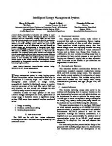
1. Introduction Plug-in hybrid car is a kind of special configuration which is a combination of pure electric vehicles and the conventional hybrid electric vehicle. Plug-in hybrid car has a large capacity of power battery that can charge the battery by power grid, so it has certain electric range [1-2]. Because of its special structure of energy distribution, Plug-in hybrid car power supply control is more complex than traditional hybrid system. The high efficient and energy saving energy management strategy becomes the key to its research [3-5]. HIL simulation is the key step of "V" cycle control system in the development process, HIL simulation platform can maximum close to the real vehicle environment. The HIL simulation can not only verify the effectiveness of the developed control strategy of the control system, but also match and optimize its parameters, so it can improve the design success rate and reduce the risk of developing. The main commercial tool chains of HIL simulation includes LabCar, dSPACE, ADRTS [6]. CAN bus has been widely used in electric vehicle control system, due to its advantages such as good real-time feature, high reliability, quick communications rate, simple structure, high flexibility and so on[7]. So it is more close to practical application that professional CAN bus simulation tools are integrated into the hardware-inloop simulation. In this paper, PHEB Powertrain structure and energy management Strategy came from Ref. [8] .First, control strategy was downloaded into the hardware based on the MotoTron control system development process. Then real-time kernel of PHEB simulation model was generated by Simulink automatic code generation technology, the real-time kernel of PHEB model was downloaded into VTSystem platform for the real-time simulation system development. The control system and real-time simulator was connected by the real CAN bus, and the CAN bus performance features were evaluated by CANoe software. The control functions and performance of the energy management system of the PHEB can be tested and improved. 2. Development of HIL simulation platform that integrate CAN monitor and evaluation function 2.1 PHEB powertrain structure and control strategy Energy management system Clutch
CAN bus
ECU
Engine
ISG
Differential
Traction motor Main reducer
ISG controller BMS
Power Battery Pack
Traction motor Electric cable controller
High-voltage distribution box
Fig.1. Powertrain architecture.
951
952
Lu Yi et al. / Energy Procedia 88 (2016) 950 – 956
In this paper, the plug-in hybrid bus powertrain adopts series-parallel structure, specifically shown in Figure 1, where the engine and ISG motor are mechanically integrated; the ISG motor is connected to the main drive motor through a clutch, specific model can reference Ref. [8] There are three kinds of energy consumption modes for PHSB, which are electric vehicle mode (EV), CD mode and CS mode. In this paper, the drive motor alone drives the vehicle during the EV mode, and all of the required energy for PHSB driving comes from the power battery packs. In the CD mode, both of the drive motor and the engine drive the PHSB, and the SoC of the power battery packs would be decreased gradually. In the CS mode, the engine provides most of the energy to drive the PHSB, and the SoC of power battery packs was maintained within an appropriate range until the PHSB stops. The energy consumption modes switching control strategy is shown in Figure 2, specific model can reference Ref. [8] Start SoC, SoC_CD, SoC_CS, o Y
SoC≥SoC_CD N SoC≥SoC_CS
Y
N EV mode
CS mode
CD mode
N SoC≥SoC_CS+o
Y
Fig.2. Mode switching control strategy.
2.2 PHEB energy management system PHEB energy management system development process was shown in Figure 3.Fisrt, PHEB energy management strategy model was set up input/output interface by MotoHawk toolkit integrated in the Simulink environment. According to requirements that calibration and monitoring of the control system, calibration module and monitoring module for parameters or variables of energy management strategy were set up. Then the real-time kernel of PHEB simulation model was generated by Simulink automatic code generation technology. Finally, CAN bus communication baud rate and the PC port was set up by MotoTune software. MotoTune software can calibrate and monitor the control parameters of energy management system online, PHEB energy management system was developed.
953
Lu Yi et al. / Energy Procedia 88 (2016) 950 – 956
MotoHawk The Simulink environment development of the control strategy Underlying module selection and configuration of MotoHawk
MotoHawk interface Settings of control strategy Automatic code generation
Energy management system
MotoTune
Communication port and baud rate setting
CAN card connect to host computer
Control program flash Control system power up
Online calibration and monitoring
Fig.3. Control system development Based on MotoTron.
2.3 PHEB real-time simulation system PHEB vehicle real-time simulation system development process is shown in Figure 4. First, the development of PHEB vehicle simulation model is completed in the MATLAB/Simulink environment, Specific model can reference Ref. [8]. By CANoe toolkit integrated in the Simulink environment, input/output interface of PHEB energy management strategy model were set up. Then the real-time kernel of PHEB simulation model was generated by Simulink automatic code generation technology, and the definition of hardware-in-loop simulation platform bus node protocol was completed by CANoe software. Finally, the real-time kernel of PHEB model was downloaded into VTSystem platform for the real-time simulation system development. CAN bus interface card can be used in data interaction between real-time simulation system and the control system. Real-time simulator development CANoe CAN ANoe signal si ignal iinput nput
Simulink S imuliink modle modl le
CANoe CA ANoe signal signal g l output outp t ut u
MATLAB/Simulink MA ATLA AB/S Simulli Si link k Embed Emb bed bed d
CANoe C AN Noe
Ethernet Ethe hern r ett cable cabl blle Real-time simulation board
Control system based on the MotoTron
AN CAN Pow Power wer signal siignal Analog Ana A allog signal siignaal
CAN bus board Signal output board Signal acquisition board VTSystem
Fig.4. Real-time simulation system development based on VTSystem.
954
Lu Yi et al. / Energy Procedia 88 (2016) 950 – 956
2.4 HIL simulation platform of driver-in-loop In order to make the HIL simulation platform be closer to real vehicle environment, real vehicle door key was used to make energy management system charged, and energy management system was input driving demand by driver controlling electronic accelerator pedal and electronic brake pedal. PHEB control system HIL simulation platform of driver-in-loop was established. Signals that Platform send and receive was shown in Figure 5, and platform's physical composition was shown in Figure 6.
USB
Energy management system development environment
CANoe Ethernet
MotoTune
CAN card
VTSystem
Real-time simulation system development environment
PHEB real-time simulation kenel CAN2H
CAN1L
CAN2L
Real-time control kenel
CAN1H
ACC Brake pedal pedal Driver-in-loop Key switch
n_ISG n Tg_req SoC Te_req Vf Tm_req Ts mode
Energy management sysytem Real controller Fig.5. Structure of HIL simulation platform for receiving and sending signal. MotoTune
CANoe
CAN2 channel
Key switch
Hub Controller
CAN Card connect to CAN1 channel
Acceleration pedal
Brake pedal VTSystem
Fig.6. Hardware-in-loop simulation platform.
955
Lu Yi et al. / Energy Procedia 88 (2016) 950 – 956
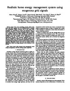
PHEB control system was in communication with PC MotoTune by CAN1 channel, so CAN1 channels were responsible for flash program and online monitoring or calibration of the control parameters. PHEB control system was also connected with CAN bus card of VTSystem to get in communication with PHEB real-time simulation system. VT System can get in communication with PC CANoe by Internet, so CANoe can monitor all message and pedal signal from signal acquisition boards in real time which are on CAN2 bus. 3. Experiment of HIL simulation To verify the validity of the control strategy, this section conducted a number of experiments by HIL simulation platform. CTBDC was downloaded in VTSystem real time board in experiments, and a complete experiment included 3 CTBDCs. Initial value of power battery SoC was set to 85%, and the total capacity was set to 10 A∙H. Simulation results are shown in the following diagram. 300 CTBDC Velocity
Demand power Total power
200 Power/kW
Velocity(km/h)
80 60
100
40 20
0
-100
0 0
500
1000
1500
2000 Time/s
2500
3000
3500
4000
-200
EV 0
Fig.7. Velocity following under driver operation.
CD&CS
CD
500
1000
1500
2000 Time/s
2500
3000
3500
4000
Fig.8. Power following under driver operation
100
SoC SoC=30%
80
SoC/%
60 40 20 EV 0
0
500
CD 1000
1500
2000 Time/s
CD&CS 2500
3000
3500
4000
Figure 9. SoC
HIL platform proves that the controller can manage energy of the vehicle model in line with driver’s expectations. Logic function can be realized normally. It shows that the control model has the conditions for the operation of the vehicle, and can be used as a part of the vehicle controller to participate real vehicle experiment in the future. 4. Conclusion In this paper, a rule based energy management strategy is used. In order to verify the reliability and real-time performance of the developed energy management strategy, the driver-in-loop's hardware-inloop simulation platform is built. Based on automatic code generation technology, those pieces of commercial software (MotoHawk, MotoTune) are used to develop PHEB energy management system. Then, VTSystem is used to develop PHEB real time simulation system. Driver-in-loop operation is realized through electronic acceleration pedal and electronic brake pedal. CANoe is used to monitor HIL simulation platform.
956
Lu Yi et al. / Energy Procedia 88 (2016) 950 – 956
China Transit Bus Driving Cycle is used as a target velocity. HIL test results show that vehicle velocity and power in real time simulation can follow the demand velocity and demand power well, so the developed energy management system can meet the requirements of dynamic performance. CD mode and CS mode can switch reversible in the second half of the ride, and SOC is stable in 30%. Working time of CD mode is effectively extended while SOC is stable, so fuel economy has been improved, which is consistent with the goal of the global optimization theory.The energy consumption per 100 km is 14.1 L diesel and 11.9 kW•h electricity with an initial SoC of 85%, so the economy requirements of the PHEB can be guaranteed. It shows that PHEB energy management system has good real-time performance and reliability. Copyright Authors keep full copyright over papers published in Energy Procedia Acknowledgements This work was supported by the National High Technology Research and Development Program of China (2013BAG05B00). The author would also like to thank the reviewers for their corrections and helpful suggestions. References [1] Bashash S, Moura S J, Forman J C, et al. Plug-in hybrid electric vehicle charge pattern optimization for energy cost and battery longevity. Journal of power sources, 2011, 196(1): 541-549. [2] Li G, Zhang X P. Modeling of plug-in hybrid electric vehicle charging demand in probabilistic power flow calculations. Smart Grid, IEEE Transactions on, 2012, 3(1): 492-499. [3] Moura S J, Fathy H K, Callaway D S, et al. A stochastic optimal control approach for power management in plug-in hybrid electric vehicles. Control Systems Technology, IEEE Transactions on, 2011, 19(3): 545-555. [4] Shankar R, Marco J, Assadian F.The novel application of optimization and charge blended energy management control for component downsizing within a plug-in hybrid electric vehicle. Energies, 2012, 5(12): 4892-4923. [5] Wirasingha, S.G.; Emadi, A. Classification and review of control strategies for plug-in hybridelectric vehicles. IEEE Trans. Veh. Technol. 2011, 60, 111–122. [6] Wang L, Zhang Y, Yin C, et al. Hardware-in-the-loop simulation for the design and verification of the control system of a series–parallel hybrid electric city-bus. Simulation Modelling Practice and Theory, 2012, 25: 148-162. [7] Zhou, F.; Li, S.Q.; Hou, X. Development method of simulation and test system for vehicle body CAN bus based on CANoe. In Proceedings of the World Congress on Intelligent Control and Automation (WCICA), Chongqing, China, 25–27 June 2008; pp. 7515–7519. [8] Peng J.K, Fan H, He H.W, Pan. D. A Rule-Based Energy Management Strategy for a Plug-in Hybrid School Bus Based on a Controller Area Network Bus. Energies, 2015, 8(6): 5122-5142.
Biography Hongwen He is currently a Professor with the National Engineering Laboratory for Electric Vehicles, Beijing Institute of Technology and a researcher with the Beijing Coinnovation Center for Electric Vehicles. His research interests include power battery modeling and simulation on electric vehicles, design, and control theory of the hybrid power train.