A hard real time system for simulation and controller implementation has been developed, based on Real ... not know if the information it is getting comes from ... for controller auto-tuning based on experimental data. .... established database allocated in the hard disk. Al- .... dead time (FOPDT or SOPDT) model is obtained.
Proceedings of the 5th WSEAS International Conference on Telecommunications and Informatics, Istanbul, Turkey, May 27-29, 2006 (pp503-508)
Hardware/Software Environment for Process Identification, Robust Controller Design and Hard Real Time Implementation Luis Garc´ıa, Manuel J. L´opez, Jos´e Lorenzo Universidad de C´adiz Dpto Ingenier´ıa de Sistemas y Autom´atica Calle Chile 1, 11003 C´adiz SPAIN Abstract: In this paper we propose a new hardware/software environment for designing and testing control systems based on H2 and H∞ methods, where an innovative procedure is used for controller tuning. Model identification and controller design are carried out by means of a new software ControlAvH, which makes transparent for the user the mathematical complexity associated with controller design, and additionally provides a friendly user interface. A hard real time system for simulation and controller implementation has been developed, based on Real Time Linux (Linux-RTAI). The complete system provides a flexible and scalable environment for controller design, implementation and evaluation with hard real time restrictions. Key–Words: Software engineering, control engineering, real time control, system identification, robust control.
1
Introduction
Traditionally, there has been a gap between the control engineers who design the components of the control system and the software engineers who implement them. So that a thorough understanding of the methodologies used in both disciplines would make the overall process more cohesive. Component-based design of control systems has several advantages over the current practice of design, especially for streamlining the transition from simulation to real implementation. Setting and abiding by standards for the interfaces between the components facilitates rapid prototyping from the simulation stage to the implementation stage. The basic idea is: Ideally, controllers, signal processing/filtering components would not know if the information it is getting comes from the simulation code or from the sensor itself. Software components may be objects such as Java application or C++ program. Properties such as encapsulation, inheritance and polymorphism are useful for implementing components [1], [4], [9], [6]. Based in this approach, we have developed a new hardware/software environment for designing and testing control systems. Controllers are designed based on H2 and H∞ methods, using an innovative procedure for controller auto-tuning based on experimental data. Model identification and controller design are carried out by means of a new software application for Windows XP: ControlAvH. This software makes transparent for the user the mathematical complexity associ-
ated with controller design, and additionally provides a friendly user interface which facilities monitoring, analysis and controller validation tasks. In order to test control systems in realistic environments and to evaluate hardware/software in the loop performance, a hard real time system based on Real Time Linux under PC platform and on data acquisition cards has been developed (EPESC). ControlAvH makes controller tuning and by means of EPESC the controller is implemented and tested; for which ControlavHEPESC system provides a flexible and scalable environment for controller design, implementation and evaluation with hard real time tests. The complete system, EDECOS (Environment for Design and Evaluation of Control Systems), is used for testing and evaluating controller design by hard real time simulation. The rest of the paper is organized in sections as follows: In section 2 ControlAvH Tune and EPESC system are described. Section 3 shows system identification methods implemented in ControlAvH, and in section 4 the implemented controller design methodology used in this work is outlined. Section 5 shows some illustrative simulation tests, and finally, conclusions are summarized in section 6.
2
EDECOS System
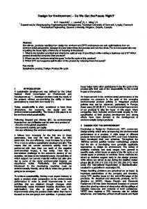
We have developed an Environment for Design and Evaluation of Control Systems (EDECOS), which consits of several components such as it is showed in Fig. 1. The main parts of the system EDECOS, which
Proceedings of the 5th WSEAS International Conference on Telecommunications and Informatics, Istanbul, Turkey, May 27-29, 2006 (pp503-508)
has been developed by our group (GAPSIS), are ControlAvH software and EPESC system. ControlAvH is used for auto-tuning controllers and EPESC function is to test controller implementation in hard real time control.
shown.
Figure 2: ControlAvH Tune structure
Figure 1: EDECOS components and connectivity ControlAvH Tune has been developed with Builder C++ [5], which is a last generation RAD (Rapid Application Development) tool that incorporates a great quantity of standards with a very fast and efficient compiler. The base language is C++ which permits rapidity, flexibility and portability of the developed software . Builder C++ permits us to design the different interfaces that the user has to execute. In the main screen of the application the following elements are considered: 1) Graphical screen for signals evolution, 2) start and stop buttons of the control system, 3) online information of the run times of different tasks, 4) set of buttons to use the graphic system, 5) controller parameters for PID, H2 or H∞ and sample time. By means of ControlAvH software application controller design and analysis are made. In order to carry out the application design we have used methods based on real time systems techniques [1], [4], [6] and on automatic control theory applied to robust controller design [21], [18], [7]; with the objective to implement different phases related with controller design and validation. This approach can be seen in Fig. 2, where ControlAvH Tune application architecture is
Each application component can be represented with classes, objects and tasks within of the application. By means of object oriented programming (OOP) high flexibility is obtained, which permits an easy joint among different components. Besides, that facilities to develop structured software in order to divide complex algorithms in smaller modules of easy resolution. Each one of components can be assembled within a generic part that can be implemented by an object oriented framework [1], [4], [6]. As it can be seen in Fig. 1, the application has an operation mode (MODE 1) which works in soft real time controlling directly the process by means of data acquisition cards. Nevertheless, in MODE 2 ControlAvH works only as controller computation and evaluation platform, so that in this case the controller (hard real time) is implemented in EPESC. Connection between ControlAvH Tune and EPESC is made by Ethernet. In MODE 1, ControlAvH works as autonomous system and it incorporates functions for controller design, analysis and controller implementation; which supposes an element of additional complexity. Data acquisition and control algorithms execution for industrial processes require strict time restrictions and reliability, due to what the following functionality characteristics must be incorporated: 1) Coordination among real-time tasks, 2) processing of interruptions and messages within the system, 3) input/output device drivers to insure that they do not lose data, 4) inlet and outlet time restriction specifications of the system, 5) databases precision. To de-
Proceedings of the 5th WSEAS International Conference on Telecommunications and Informatics, Istanbul, Turkey, May 27-29, 2006 (pp503-508)
velop this software application with such restrictions, it is very important to take into account software engineering principles to avoid possible bottlenecks and to be able to get the optimal performance from hardware and software. ControlAvH has been developed under Windows XP, so that only soft real time is guaranteed. Data from real time signals that the control application must register are the following: Time, process variable (PV), controller output (CO) and setpoint (SP), since error signal is obtained from E=SPPV. These data are used by algorithms related with system identification methods, controller design and implementation, control system analysis, system simulation, as well as system temporary evolution visualization interface. Due to for system identification the software must work in real time (at least soft real time), the storage system can not reside in an established database allocated in the hard disk. Although a possibility is to use a virtual disk in memory RAM, however this technique is little standardized, and is very dependent upon the Operating System. The adopted solution implements the storage system through a class that reserves main memory dynamically. The application is based on a monolithic architecture under Windows OS, and the amount of memory available to reserve in this system is 2 Gbytes. Data communication and interface system implements the following methods: 1) Ethernet via TCP/IP, 2) RS232 interface, 3) Sockets, 4) NetDDE communication standard, 5) OPC communication standard. Methods 1 and 2 are directly related to hardware components and to the operating system of the computer, for what the developed software is far away from open standards implemented by means of middleware software. The data acquisition devices that we have worked with are from National Instruments [15]. By means of the NIDAQ library we have implemented functions of higher level that enable its communication. The software technologies NetDDE and OPC have been implemented in ControlAvH Tune for distributed communication among computers. These methods permit to establish communication among computers in a network, which facilitates to share data of distributed equipments with client-server structure. For each one of the communication methods given before, a library for Builder C++ has been implemented. Commercial software tools for control systems, such as VisSim from Visual Solutions [19] or Matlab/Simulink from The MathWorks [14], are aimed at design and analysis. Matlab is used in conjunction with the Simulink package to provide a blockdiagram-based graphical user interface along with some expanded simulation capabilities. To ease system implementation, the Real-Time Workshop Toolbox can be used to generate C code automatically
from Simulink block diagram. VisSim works in similar way. Both products tend to generate monolithic code rather than component-base code, which makes it more difficult to validate or update the code. Matlab/Simulink has been mainly used for developing and implementing TuHiCo Toolbox (Tuning of H-infinity and H-2 Controller Toolbox) and GARCO (Genetic Algorithms for Robust Controller Design) Toolbox (see Fig. 1). EPESC: Hard Real Time Control and Simulation. EPESC system is based on PC-based controllers and PC-based plant simulators; due to PC-based environments are cheaper than the industrial-grade processors and have a more open architecture. This open architecture means that third-party vendors are able to supply more of the components. Communication between PCs is based on the Ethernet hardware, as it is outlined in Fig. 1. Low-cost communication protocols suggested the use of TCP/IP or UDP/IP, which are nonproprietary communication protocols. The TCP/IP protocol guarantees, via implicit acknowledgment, receipt of data packets, but occupies a wider network bandwidth. The UDP/IP protocol is faster, but does not guarantee absence of packet losses. Basically, the communication between PC1 and PC2 consists of controller matrices, tuning parameters and data for controller analysis and fine tuning. For that, we have adopted the TPC/IP protocol. The essence of real-time systems is that they are able to respond to external stimuli within a certain predictable period of time. Building real time computing systems is challenging due to requirements for reliability and efficiency, as well as for predictability in the interaction among components. Real-time operating systems (RTOS) such as VxWorks [20], QNX [16] and LynxOS [12] facilitate real-time behavior by scheduling processes to meet the timing constraints imposed by the application. Control systems are among the most demanding of real-time applications. There are constraints on the allowable time delays in the feedback loop (due to latency and jitter in computation and in communication), as well as the speed of response to an external input such as changing environmental conditions or detected faulted conditions. If the timing constraints are not met, the system may become unstable. EPESC system consists of hardware (input/output interface and electronic cards for data acquisition) and a software application developed with C/C++ language, Linux Operating System and RTAI (Real Time Application Interface for Linux). RTAI lets to develop applications with strict timing constraints, but has the difference with respect to other real time operating systems (QNX, VxWorks, LynxOS) that, like Linux itself, this software is a community effort and
Proceedings of the 5th WSEAS International Conference on Telecommunications and Informatics, Istanbul, Turkey, May 27-29, 2006 (pp503-508)
freeware. RTAI supports several architectures, such as x86/Pentium or PowerPC [17]. Such as it is shown in Fig. 1, EPESC is used for hard real time controller implementation and for process simulator, both implemented with PC.
3
System identification
System identification is essential for controllers design techniques based on process model, which go from PID controller [2], [3] to more sophisticated methods such as H2 and H∞ control [21], [18], [7]. In industrial processes control, generally, control engineers must carry out controller design and tuning using, mainly, experimental data of the plant; and theoretical studies are not always available and/or useful for controller design. For that, an usual and practical approach employs a process mathematical model which is obtained from experimental data when the process is working near of a specified operating point [10], [3]. In order to get useful mathematical models which can be used for posterior linear controller design, we have selected and implemented a set of identification techniques which we have probed with real processes and simulated systems and which are specially useful for PID, H2 and H∞ controller design. The following identification methods have been implemented in ControlAvH Tune: 1) Method based on the process reaction curve (RCM). With this method a first (or second) order plus dead time (FOPDT or SOPDT) model is obtained. These models are widely used in process control to design PID controllers, and most of the industrial process have dynamics which may be approximated with some of these models. 2) Methods based on Finite Impulse Response (FIR) model, and on Finite Step Response (FSR) model. 3) Method based on pulse frequency response (PFR) and Fourier transform. 4) Methods based on stochastic models (SM), for ARX/ARMAX processes and general stochastic model; which are specially indicated when stochastic disturbances and measurement noise are significant. These identification methods have been previously implemented and tested in Matlab, for which TuHiCo Toolbox was used [11], and later, adaptation and real time properties have been added to ControlAvH Tune.
4 H2 and H∞ Controller Design For controller design, an equivalent conventional closed loop is considered, which consists of plant (G), controller Gc , set-point or reference signal (r), measurement noise (n), disturbances acting at the plant input (di ) and at the plant output (do ). The signals to
evaluate the performance of the system are the control signal (u), the output signal (y), and the error signal (e = r − y); where signals are multivariable and nominal mathematical models for G and Gc are considered LTI (Linear Time Invariant). In this scheme, it is considered a vector z, which is used to include signals required to characterize the behavior of the closed-loop system, and a vector w which contains external inputs (set-points, disturbances and noise). So that, the behavior of the closed-loop system is given by z = Tzw w, where input-output transfer function Tzw depends on the weighting transfer functions employed in the design problem. In our approach, H2 and H∞ controllers are designed for robustness and performance specifications expressed in the frequency domain; but indicators based on time domain response such as overshoot, rise time and settle time, are considered too. In practice, it is difficult to obtain specified time responses, for what we employ a innovative tuning method [11], which gives parameters for controller pre-tuning, controller evaluation indicators and a method for controller fine tuning. In the first step, pre-tuning values for performance and robustness are established by means of the suboptimal H∞ problem, kTzw k∞ < γ (γ > 0) is considered, with Tzw = [WS S dWR Gc S WT T ]T where S = (I + GGc )−1 is the sensitivity function, T = (I + GGc )−1 GGc is the complementary sensitivity function, and R = Gc S is the control sensitivity function; or by means the optimal H2 problem, minGc kTzw k2 , where the weighting transfer functions are obtained from the identified model of the plant following the pre-tuning formulae given in [11], valid for SISO and MIMO processes. In conventional approach of H∞ control, controller is designed for robustness and performance specifications expressed in the frequency domain [21],[7]; but usual indicators based on time domain response such as overshoot, rise time and settle time, are not considered a priori. In practice, it is difficult to obtain the specified time responses using this approach, for what in EDECOS (see Fig. 1) a method to satisfy time response specifications as well as robustness properties is implemented. For that, H∞ control theory and genetic algorithms (GA) are employed in our design. We have implemented the following procedure for controller design: 1) Time domain specifications are established for rise time (tr ), overshoot (Mp ), settle time (ts ) and stationary error (ess ) for a step change in set-point. 2) Suboptimal H∞ problem, kTzw k∞ < γ (γ > 0) is considered. 3) Weighting transfer functions are given by the set, {WH } = {Wr , Wn , Wdo , Wdi , WT , WR , WS },
Proceedings of the 5th WSEAS International Conference on Telecommunications and Informatics, Istanbul, Turkey, May 27-29, 2006 (pp503-508)
where pre-tuning parameters of WH are obtained following [11]. 4) Controller is solved through standards algorithms for H∞ and H2 problems. If more adjusted restriction on time response is necessary, genetic algorithms are used, employing the following objective function: f (k) = w1 |Mp (k)−Mpo |+w2 |tr (k)−tro |+w3 |ess |, where Mpo , tro , ess are respectively the specified (objective) overshoot, rising time and steady-state error; and wi (i = 1, 2, 3) are weighting factors. Here, GA are used for obtaining weighting transfer functions parameters, once these parameters are fixed, conventional algorithms are used for solving kTzw k∞ < γ, or minGc kTzw k2 .
rn-
Wr - e Wn
e
- WS -z1
q
6 -e 6
? -WR -z2
doWdo diWdi
- e6
G
u
e
-
Gc
Figure 3: Generalized plant for H∞ and H2 control
5
Simulation tests
In this section we present some illustrative simulation examples for MIMO systems: P1 corresponds to a stable system with two inputs and two outputs (rocket propeller), P2 has an unstable pole with two inputs and two outputs (helicopter), and P3 is stable with three inputs and three outputs (aircraft). Next, the state space matrices of the corresponding linearized systems are given: P1: Rocket propulsor [13]
A=
B=
−65 65 −19.5 19.5 0.1 −0.1 0 0 1 0 −0.5 −1 0 0 0.4 −0.4 65 0 0 0 0 0 0 0.4
A=
B=
, CT =
0 0 1 0
0 0 0 1
−0.02 0.005 2.4 −32.0 −0.14 −0.44 −1.3 −30.0 0 0.018 −1.6 1.2 0 0 1 0
0 0 0.14 −0.12 0 0.36 −8.6 1 , CT = 0 0 0.35 0.009 0 57.3 0 0
P3: Aircraft [13], with matrix A =
?yq WT -z3 -e
P
�
P2: Helicopter [13] (unstable system)
0 0 1.132 0 −1 0 −0.0538 −0.1712 0 0.0705 0 0 0 1 0 0 0.0485 0 −0.8556 −1.013 0 −0.2909 0 1.0532 −0.6859
B=
0 −0.12 0 4.419 1.575
0 0 1 0 0 0 0 −1.665 0 −0.0732
T ,C =
1 0 0 0 0
0 1 0 0 0
0 0 1 0 0
All controllers have been obtained using a pre-tuning method based on previous work [11]. In Fig. 4, 5 and 6 the temporary responses for each system are given. It can be seen that step responses of P1, P2 and P3 have low loop interaction and there is not overshoot. These results correspond to pre-tuning stage with the linearized models (using TuHiCo Toolbox); nevertheless, specified time response indicators are obtained using a procedure based on genetic algorithm optimization (using GARCO Toolbox). Finally, hard real time control tests must be carried out employing the nonlinear model of the processes, EPESC system and ControlAvH Tune software, where operator can carry out the controller fine tuning in real time.
6
Concluding remarks
The software engineering application developed in this work is focused for control engineering. It results a flexible hardware/software environment for hard real time simulation and controller evaluation: EDECOS. An on-line design of H2 and H∞ regulators is realizable by means of ControlAvH Tune software; which incorporates a new and automatic method for controller tuning. In this first stage, distributed systems has not been considered, for which real-time CORBA will be used in next works.
Proceedings of the 5th WSEAS International Conference on Telecommunications and Informatics, Istanbul, Turkey, May 27-29, 2006 (pp503-508)
1 PV (SP1)
1
PV (SP1)
0.8 0.6
0.5
0
0.4 0.2
0
0.5
1
1.5 Time (sec)
2
2.5
3
0
0.5
1
1.5 Time (sec)
2
2.5
3
0
0.5
1
1.5 Time (sec)
2
2.5
3
0 0
0.5
1
1.5 Time (sec)
2
2.5
3
PV (SP2)
1 −0.2
0.5
0 1
0.6
1 PV (SP3)
PV (SP2)
0.8
0.4 0.2 0 −0.2
0 0
0.5
1
1.5 Time (sec)
2
2.5
3
Figure 4: P1 time responses for changes in SP1 and SP2
1
PV (SP1)
0.8 0.6 0.4 0.2 0 −0.2
0
0.5
1
1.5 Time (sec)
2
2.5
3
0
0.5
1
1.5 Time (sec)
2
2.5
3
1
PV (SP2)
0.8 0.6 0.4 0.2 0 −0.2
0.5
Figure 5: P2 time responses for changes in SP1 and SP2
References: [1] A. Abran and J.W. Moore, executive editors, Guide to the Software Engineering Body of Knowledge. IEEE Computer Society, 2004. [2] K.J. Astrom and B. Wittenmark, Adaptive Control. Addison-Whesley, 1995. [3] K.J. Astrom and T. Hagglund, PID Controllers. Instrument Society of America, 1995. [4] S. Bennet, Real Time Computer Control. Prentice-Hall, 1998. [5] Builder C++.
http://www.borland.com.
[6] V. Gazi, M. L. Moore, K.M. Passino, W.P. Shackleford, F.M. Proctor, J.S. Albus, The RCS Handbook. Tools for Real-Time Control Suystems Software Development. Wiley, 2001.
Figure 6: P3 time responses for changes in SP1, SP2 and SP3
[7] M.J. Grimble, Robust Industrial Control: Optimal Design Approach for Polynomial Systems. Prentice Hall, 1994. [8] D. Gu, P.H. Petkov, M.M. Konstantinov, H∞ and H2 Optimization Toolbox in SLICOT. http://www.slicot.de, SLICOT software library, 1999. [9] B. S. Heck, L.M. Wills and G.J. Vachtsevanos, Software Technology for Implementing Reusable, Distributed Control System. IEEE Control System Magazine pages 21-35, February 2003. [10] L. Ljung, System Identification: Theory for the User. Prentice Hall, 1987. [11] M.J. L.´opez, Contributions to Advanced Process Control. Methods for H∞ Controller Tuning. C´adiz University, 1999. [12] LynxOS RTOS. http://www.lynuxworks.com [13] Pang G.K.H., A.G.J. MacFarlane, An expert system approach to computer-aided design of Multivariable Systems. Springer, 1988. [14] MathWoks Inc. Matlab. http://www.mathworks.com [15] National Instruments Corporation. Measurement and automation catalog. http://www.natinst.com [16] QNX Software Systems. http://www.qnx.com [17] RTAI. http://www.aero.polimi.it/ rtai [18] S. Skogestad, I. Postlethwaite, Multivariable Feedback Control. Wiley, 2003. [19] Visual Solutions Inc. VisSim. htttp://www.vissim.com [20] VxWorks RTOS. http://www.windriver.com [21] K. Zhou, J. C. Doyle and K. Glover, Robust and Optimal Control. Prentice Hall, 1996.