HELLAS: A Specialized Architecture for Interactive ... - Semantic Scholar
Recommend Documents
INTRODUCTION. Internet Protocol Multimedia Subsystem (IMS) ... ment) how IMS-TV can support interactive and ... to safeguard business and consumer integri- ... Rittwik Jana, John Murray, and Christopher W. Rice, AT&T Labs Research.
Specialized Computer Support Systems for Medical Diagnosis. Relationship with the Bayes' Theorem and with Logical. Diagnostic Thinking. Update. âNo one ...
Communicated by Henry Lardy, September 13, 1974. ABSTRACT. Specialized lambda transducing phages have been isolated carrying approximately half the ...
Nov 21, 2016 - Abstract: Children and adolescents with highly disabling chronic pain of high intensity and frequency are admitted to specialized pain ...
Recently, we suggested that onychodermis might be in- volved in the development of onychomatricoma based on histology and CD10 immunohistochemistry10.
Oct 14, 2015 - Wong, H.; Yauch, R.L. Discovery and preclinical development of vismodegib. Expert Opin. Drug Discov. 2014, 9, 969â984. [CrossRef] [PubMed].
Janse and Warner ten Kate. REFERENCES. [1] J.F.K. Buford, Architectures and Issues for Distributed. Multimedia Systems, in J. F. K. Buford(Ed.), Multimedia.
[Gerhardt-Powals, 1996], mobile applications (e.g., [Bertini et al., 2006]) ... its developers, because the cost of early interface changes is one-quarter that of late ...
A specialized fast cross-correlation for acoustical measurements using coded sequences a). John N. Daigle. Department of Electrical Engineering, Anderson ...
Feb 22, 2013 - Naeije M: Measurement of condylar motion: a plea for the use of the condylar kinematic centre. J Oral Rehabil. 2003, 30(3):6. 26. Seitz SM ...
this automaton is translated into a C code to be executed. This multistage ..... generate a C (or Ada) code implementing the automaton. In Section 4.1, we have ...
a scene in a screenplay. A screenplay may contain some blocking, the general mood of the scene, even ..... As Syd Field wrote,. âDrama is conflict,â (Field 1994).
availability of an intelligent default suggestion mechanism for commands. .... The result of its computations is the domain of y â u, which is the matcher of. R(y) and R(u). Thus ... We use Argument Agents as generic name for both agent types.
ments (premises, conclusions and additional arguments). .... Predicate Agents searching for premise arguments .... demand suggestions in no particular order.
calls into an operational, automated DA call center and an. FRN set size of 25000 numbers, the new architecture is capable of delivering more than 17% correct ...
Psychological and neurophysiological concepts related to perceptual .... measurable relations: Gestalt psychology proposes a number of Gestalt laws,.
TOWARD A GENERIC ARCHITECTURE FOR MULTISOURCE INFORMATION FUSION. John R. Josephson and B. Chandrasekaran. Ohio State University.
agents are dedicated to the evaluation of the sensors information (target .... A Java server has been hosted on the PPC for allowing the communication between ...
The template is based on a VLIW processor with a reconfigurable in- struction set. .... the ARM Thumb (a), the REAL DSP (b) and the Chimaera (c). The sizes of ...
The architecture described in [ 3] proposed a centralized broker architecture for ... model the sequence of the message exchange from the viewpoint of an ...
republish, to post on servers or to redistribute to lists, requires prior specific permission and/or a fee. ..... non-player characters, while the exact information can be received directly from the ..... 1500 archers on a 28.8: Network programming a
sensor nodes. Internet. Fig. 1. A possible scenario for heterogeneous WSNs with management devices. ..... By clicking on the hosting MN (e.g. mn01) .... installation, as these SN platform features the fastest radio module (CC2420 with.
Nov 30, 2011 - Ali, K.; Hassanein, H. Underwater wireless hybrid sensor networks. In Proceedings of the IEEE. International Symposium in Computers and ...
HELLAS: A Specialized Architecture for Interactive ... - Semantic Scholar
ABSTRACT Applications involving interactive modeling of deformable objects require highly iterative, floating-point intensive numerical simulations. As the complexity of these models increases, the computational power required for their simulation quickly grows beyond the capabilities of current general purpose systems. In this paper, we present the design of a low–cost, high–performance, specialized architecture to accelerate these simulations. Our aim is to use such specialized hardware to allow complex interactive physical modeling even on consumer-grade PCs. In this paper, we present details of the target algorithms, the HELLAS architecture, simulation results and lessons learned from our implementation.
Categories and Subject Descriptors B.7.1 [Integrated Circuits]: Types and Design Styles— algorithms implemented in hardware
General Terms Computer Graphics
interactive physical modeling, deformable objects, floating– point intensive, specialized hardware
1.
more realistic models, it is likely that the computational resources required by these simulations may continue to exceed those provided by the incremental advances in generalpurpose systems [12]. This has created an interest in the use of specialized hardware that provides high performance computational engines to accelerate such floating-point intensive applications [6, 7]. Our research focuses on the design of such specialized systems. However, our approach has several important differences as compared to previous work in this area: (i) we specifically target algorithms that are numerically stable, but are much more computationally intensive than those used by existing hardware implementations [3,6]; (ii) we aim to design a low-cost implementation that can allow these applications to be run at interactive speeds even on consumergrade systems; and (iii) rather than implement only a particular application in hardware, we propose a reconfigurable system that can support a broad class of applications (fluid dynamics, ray tracing, etc.) that use algorithms similar to deformable object modeling. In this paper, we describe the design and implementation of such a specialized hardware system, which we term HELLAS.
1.1
Keywords
INTRODUCTION
Interactive physical modeling of deformable objects is important for a number of applications areas like 3D gaming [8], surgical simulations [4], wargame simulations and others. Interactive simulation of such models requires highly iterative, floating-point intensive, numerical computations and is difficult because the simulation must be advanced under real-time constraints. With an increasing demand for
Permission to make digital or hard copies of all or part of this work for personal or classroom use is granted without fee provided that copies are not made or distributed for profit or commercial advantage and that copies bear this notice and the full citation on the first page. To copy otherwise, to republish, to post on servers or to redistribute to lists, requires prior specific permission and/or a fee. ACM SE’06 March 10-12, 2006, Melbourne, Florida, USA Copyright 2006 ACM 1-59593-315-8/06/0004 ...$5.00.
Existing work on the design of special–purpose hardware focuses mainly on the following areas: (i) acceleration of specific applications (e.g. the GRAPE project that targets N-body gravity computations [10]) and (ii) implementation of less computationally expensive, but numerically unstable, algorithms (e.g. simple explicit integration techniques) for physical modeling [3,6]. Recent work has proposed the use of Graphics Processing Units (GPUs) (for example, NVIDIA’s GeForce FX) for accelerating sparse linear solvers [7]. But these suffer from drawbacks which we explain in Section 5. Due to well-known problems in performing floating point arithmetic using programmable logic [9], FPGAs are also not a suitable platform for implementing these algorithms. Further, due to the widespread interest for deformable object modeling in the graphics community [14], there is an active need for specialized systems to accelerate these applications. Recently, Ageia Technologies [1] has proposed a specialized processor, called Physics Processing Unit (PPU) [2], to accelerate physics–related calculations in the context of computer gaming. However, very few technical details of their design are publicly available. This paper describes the design and implementation of a
point. Large simulation time steps are required to meet real-time constraints and the main concern when choosing an algorithm is its numerical stability when performing such steps. It would be convenient to use a simple explicit integration technique, such as forward Euler (p. 710 of [15]), but these techniques frequently become unstable if a large static step size is used [5]. Stability could be enhanced by using an adaptive step size, but this approach is unsuitable in interactive simulation because any step size would have to be broken down into a (very) large number of explicit steps. This makes it impossible to guarantee completion within the time needed to update the display. For the applications mentioned above, we would prefer to trade accuracy for speed and stability, which has led to the adoption of implicit methods for interactive simulation. Baraff et al. [5] justify the use of implicit integration techniques to allow large simulation steps. This class of algorithms results in a system of partial differential equations (PDEs) that are linearized in each time step. The linear system thus obtained is sparse and an iterative solver such as Conjugate Gradient (CG) [13] can be applied to produce the solution. Thus, every simulation step consists of two loops - an outer loop which linearizes the PDEs and sets up the sparse system which is then iteratively solved by the linear solver in the inner loop. The reader is referred to the work by Baraff and Witkin [5] for a thorough treatment of this approach. A rough outline of the algorithm structure can be given as follows:
Memory Footprint
4
5
x 10
Number of 32−bit words
4.5 4 3.5
Cube
3
Cloth
2.5 2 1.5 1 0.5 0
1
2
3
4
5
6
Subdivisions
(a) Memory Footprint
6
8
x 10
FLOPS per Simulation Iteration
7
6
Cube FLOPS
5
4
Cloth
3
2
1
0
1
2
3
4
5
6
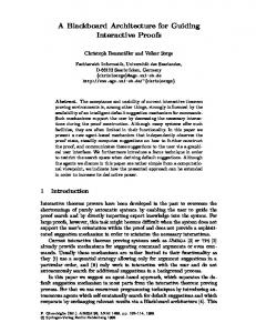
for (each simulation iteration) do linearize PDEs for (each solver iteration, while error > tolerance) do various matrix/vector operations update display
Subdivisions
(b) FLOPS Figure 1: Computational Resources for different Model Complexities low cost, proof–of–concept system to allow real–time physical modeling of complex scenes. We first present a brief description of the algorithms used for modeling and simulation of deformable objects. We outline our rationale behind designing specialized hardware to accelerate these algorithms based on a simulation study. We then provide details of the HELLAS architecture, its operation and the design flow we followed for its implementation. Finally, we describe results using a software prototype of HELLAS and our ongoing work on a hardware prototype. Our first implementation is a small, proof–of–concept system and was heavily constrained by the available die area for fabrication (only 7.5 sq. mm. was available). Hence, currently the hardware is not high– performance, however, simulation studies using our software prototype demonstrate the potential gain from hardware acceleration.
2.
ALGORITHM DETAILS
Among several different methods, mass-spring systems are commonly used for representing and animating deformable objects. In this approach, an object is described as a collection of mass points connected by springs. Simulation is achieved by advancing through (in our case uniform) discrete time steps and computing the degrees of freedom (DOFs), such as position, velocity, etc., associated with each mass
57
We measured the computational resources required for such a simulation in terms of the memory and the number of floating point operations (FLOPS) for different levels of modeling detail. We analyzed these for models ranging from a simple 2D mesh (“cloth”) to a complex 3D uniform grid (“cube”). Figure 1 shows the memory footprint and FLOPS vs. the number of subdivisions, which correspond to the level of detail, for each model. We observe that, with increasing model complexity, both the amount of memory and the FLOPS required grow rapidly. Current general purpose systems typically support up to 4 streaming floating-point functional units per chip and hence are unlikely to provide the high performance required to simulate such complex models in real-time. Hence, we believe that specialized hardware is likely the best solution to accelerate these algorithms. More details on our simulation study can be found in [16].
3.
THE HELLAS ARCHITECTURE
Our design was motivated by the observation that the high computational power required for detailed simulations can be provided by increasing the number of streaming floatingpoint units (FPUs). Further, simulations show that such applications exhibit large amounts of parallelism due to matrix operations and consist of relatively simple iterations (of the CG solver) that require only a small amount of memory for each iteration. Hence, very high performance can be obtained by distributing computations over a large number of independent units on a single chip where each unit provides
56
128x40
WestOvrWrdIn
OvrWrdData
1
2
CMEM CE
R1 R2 R3
40
Bank = 4
Bank = 7
[6:0] + 33 0’s
CMEM Addr
OvrWrdCtrl
56
CMEM Wrt
NorthOvrWrdIn
CMEM
PC
CMEM OE
OR OvrWrd
40
3
Bank = 0 32
R4
128x32
R4
OMEM
16
South/East OvrWrdOut
ResultSel
PC−Enable
YCoord
COMM
[31:0] + 8 0’s
OutWrdSel
R1/R2/R3/R4 Wrt
XCoord
R1/R2/R3/R4 OE
CLK
R1/R2/R3/R4 CE
R1/R2/R3/R4 Addr
R1/R2/R3/R4 AddrSel
[31:0] + 8 0’s
32
WestCommIn 32
NorthCommIn 32
EastCommIn
(from CMEM)
32
SouthCommIn DIRECTION
Figure 2: Architecture of a Single Processing Element W ON−CHIP
N
INTER−
S
I/O CTRL
0
CMEM PC
CONNECT
00 − NOP
E
10 − PUT INTER−PE
CLK
COMM
PC−ENABLE X−COORD FPU
Y−COORD
1
OMEM 0 128x32
5
8
PE
OPCODE
128x40
XCoord YCoord
15
Bank
55
Offset
VALUE
000 − 011 OMEM 111 PC
01 − LookUp
100 CMEM
11 − FoundIt
101,110 UNUSED
OMEM 1 128x32
(a) OverRide Mode
OMEM 2 128x32 OMEM 3 128x32
3
0
(0,0)
OPCODE ARITHMETIC
0000 − NOP 0001 − ADD 0010 − SUB 0011 − MULT 0100 − MAC 0101 − DIV CONTROL − 0110 − BLZ 0111 − LOAD COMM 1000 − STORE
INPUT
BOARD
CLK
LEVEL INTER− CONNECT
PC−ENABLE OUTPUT
(n−1,n−1)
12
R1
21
Bank 0
39
30
R2 R3
R4
Offset 1
8
(b) Compute Mode
Figure 3: HELLAS Architecture Overview Figure 4: Command Formats for different modes a tight integration of floating-point arithmetic and memory. By using a simple on-chip interconnect between these units, a high performance, low-cost architecture can be designed. Thus, HELLAS consists of a regular array of independent processing elements (PEs) where each PE integrates a fast FPU with a small control and operand memory. Inter-PE communication is enabled by directly linking each PE (except those at the boundaries) to its cardinal neighbors (East, West, North and South). Large off-chip communication delays are avoided by allowing off-chip transfers only at the north-west (i.e. PE[0][0]) and south-east (i.e. PE[n-1][n1]) corners of the chip. Figure 3 illustrates an overview of HELLAS.
3.1
PE Architecture
Each PE consists of a FPU, 4 SRAM banks, each with 128x32 operand memory (OMEM), a single 128x40 SRAM bank as control memory (CMEM), inter-connect register (COMM), I/O processing units for on-chip and off-chip links and a small control unit. The FPU is capable of performing
58
addition, subtraction, multiplication, multiply-accumulate and division of 32-bit floating-point numbers. Having four OMEM banks allows operations of the form A + B × C → D to be performed in a single clock cycle. Each PE is uniquely identified by its X-coordinate and Y-coordinate. For efficient on-chip communication without a large routing overhead, the design employs a simple nearest-neighbor interconnect. Figure 2 provides a detailed illustration of the PE architecture.
3.2
PE Instruction Set Architecture
The PE array operates in two different modes, termed as the OverRide and Compute modes, selected using a single global signal called PC-Enable (for Pipe-Compute). The OverRide mode uses a 56-bit control word (Figure 4(a)) that identifies the target PE and specifies the location (bank and offset) where the data/instruction is read/written. PUT and LookUp are used to write and read the memory banks, re-
(a) Die Photo
(b) Packaged IC
Figure 5: HELLAS Implementation spectively. Every LookUp results in a FoundIt response that populates the VALUE field with the resulting data. The Compute mode ISA supports a 40-bit control word that specifies the opcode, up to three source operands, and a single location for the result write-back (Figure 4(b)). Each location field uses 2 bits to specify the OMEM bank and 7 bits for the offset within the bank. The opcode consists of the arithmetic instructions, ADD, SUB, MULT, MAC and DIV, and a conditional branch instruction, BLZ. Interconnect is supported using the LOAD and STORE instructions. LOAD is used to access the COMM of a neighboring PE specified by a DIR field (north, west, south, east). STORE is used to write to the local COMM so that it can be read by any of the neighboring PEs.
3.3
Operation
During operation, a schedule of instructions is determined a priori on a host machine and downloaded to the PE array using the OverRide mode. At each clock cycle, data and instructions are piped across the array in a 2D wave starting from the north-west corner. The target PE is identified in each instruction and if the command is not for the PE then it sends the data unchanged to it’s south and east neighbors. If the command is for the PE, then the required operation is performed according to the opcode. In the Compute mode, each PE executes the instruction from the CMEM location pointed by the program counter (PC) and stores the result in its OMEM. Results can be communicated to neighboring PEs using the COMM register. This simple dual-mode scheme results in reduced overhead for off-chip transfers and allows control of the array using just two global signals – clock and PC-Enable.
3.4
Implementation
We followed a register–transfer–level (RTL) to layout design flow using the Cadence suite of CAD tools. The entire system was represented in VHDL and the simulation, synthesis, floorplanning and place–and–route was performed using these CAD tools. We used the TSMC 0.18 µm standard cell library provided by ArtisanTM for synthesis. The
59
operand and control SRAMs were designed using a 0.18 µm memory compiler, also from ArtisanTM . The chip was fabricated by MOSIS [11] as a 84-pin Leadless Chip Carrier (LCC) package. We had to make a number of modifications to our initial design in order to fit it into the 7.5 sq. mm. area limit specified by MOSIS. First, to reduce the number of I/O pins, we modified the I/O processing block of each PE so that the 56-bit input word was fed and read to/from each PE using two consecutive cycles with 32 bits of data each. Although this reduced the operating frequency, the functionality of the chip was largely unaltered. Second, we had to reduce the number of PEs so that the final chip contained only a 2x2 array of PEs. Figure 5 shows the die photo and the packaging of the fabricated chip. The final design consists of 99000 NAND2 equivalent gates and can support a maximum clock rate of 227 MHz. The average power consumption (assuming a switching probability of 0.5 at each internal node) was found to be 35 mW. However, this data (obtained from the synthesis tool) does not include the area, timing and power required by the SRAM banks as we did not have the layout views of the memory blocks (the memory blocks were represented as “black boxes” in the VHDL description). We hope to get more accurate data using actual fabricated chips.
4. 4.1
PROTOTYPE TESTING Methodology
Our current design is a proof-of-concept system and hence our intent was to prove the viability of HELLAS to support deformable object modeling rather than focus on a high performance implementation. To achieve this, we first designed a cycle-accurate functional simulator of HELLAS to study the execution characteristics of deformable object modeling applications and their mapping to the HELLAS architecture. Second, to study the execution of the mapped operations on the test chips, we designed a hardware prototype that allows the chip to be connected to a Linux host using a parallel port. The details of the software and hardware prototypes and the lessons learned from them are provided
Figure 6: The HELLAS Hardware Prototype in the following sections.
4.2
Software Prototype
The software prototype consists of our implementation of the algorithms proposed by Baraff et al. [5] and their mapping onto the HELLAS architecture. The prototype currently supports solid object simulations of two models: the 2D mesh (“cloth”) and 3D uniform grid (“cube”). Models are generated automatically with an arbitrary level of detail specified by the user. We believe that these models are representative of the range of model complexities that one might wish to simulate. A relatively simple gravity– driven simulation was used. In the “cloth” simulation, one edge of the cloth was constrained and no collision detection was used. For the “cube” simulation, simple collision detection using control points was used (control points are additional points connected to the mass points by zero–length stiff springs). The prototype runs two parallel simulations – one on the native processor and the other on the HELLAS simulator. The simulator starts by describing the models at the specified complexity and then applies implicit integration (as explained in Section 2) resulting in a large sparse linear system. This system is linearized and solved by a Conjugate Gradient Solver using multiple iterations. Each iteration is executed on the host machine as well as the HELLAS simulator and the values obtained by both simulations are compared to check the accuracy of the simulator. Figure 7 shows a snap-shot of both the models during simulation on the HELLAS simulator. Since our main aim was to study the execution of these applications on HELLAS, we made some minor simplifications to the simulator. First, we assumed that each PE has unlimited operand and control memory. Second, to keep the simulation simple, we designed a schedule where only one of the PEs performed all the computations while the others were used solely for communication. We ensured that these caveats do not affect the PE array functionality in any way.
4.3
Hardware Prototype
For our hardware prototype, we were limited to the use of low-tech components due to severe budget constraints. A parallel port was used as the communication channel be-
60
(a) Cloth with 6 subdivisions
(b) Cube with 4 subdivisions
Figure 7: Snaphots of models simulated using the software prototype
tween the host Linux system and the prototype. The prototype system’s clocks are generated directly from parallel port control signal pins, greatly limiting the prototype system’s maximum clock frequency. The chip accepts 32 bits of data and produces 32 bits of data per clock cycle. Data between the host and prototype systems are multiplexed four bits per clock cycle, further limiting the rate at which the chip itself can be clocked. As a result of these constraints, the prototype’s clock frequency is 16.1 KHz. Physically, the prototype system consists of three parts: input subsystem, the chip, and output subsystem. The input subsystem includes eight four bit registers, independently controlled to latch the multiplexed input data. The output subsystem is four eight-to-one multiplexers. Both subsystems use voltage converters to convert between the parallel port’s TTL voltage levels and the 1.8 V levels of the chip. The entire system was breadboarded with discrete wires. The chip uses a 1.8 V power supply. At the test system’s low clock frequency of 16.1 KHz, chip current draw was unmeasurable. Figure 6 illustrates the block diagram and the actual implementation of the prototype. Currently we are running regression tests to check the correct operation of the fabricated chips. We intend to use these chips to
demonstrate sample animation sequences using simple models. Our philosophy behind this prototype has been to design a small proof-of-concept system to demonstrate the viability of HELLAS and not to develop a high-performance implementation. Once this viability has been established, we plan to focus on building a second generation system that would focus primarily on high performance. However, it is clear that as the number of streaming floating-point units on HELLAS are increased, the performance obtained would likely be much higher than that provided by general-purpose systems.
5.
CONCLUSIONS AND FUTURE WORK
A number of lessons were learned during the design of HELLAS and from our analysis using the simulator which allow us to point to future research directions in this area. Recall that deformable object simulation consists of two loops - the outer loop which linearizes the PDEs and the inner, solver loop which performs matrix operations (Section 2). From our analysis, we found that it would be difficult to achieve high performance by accelerating only the inner loop in hardware because the I/O overhead for every simulation iteration would dominate the total execution time. Recent work which proposes the use of Graphics Processing Units (GPUs) (for example, NVIDIA’s GeForce FX) for accelerating sparse linear solvers [7] is also likely to suffer from such high I/O overhead. Hence, both the loops need to be implemented in hardware to achieve speed-up. However, we found that the control memory in our current implementation was insufficient to handle the large number of instructions to support both the loops. Thus, increasing the control memory size would be a priority in designing future generation systems. The efficiency of HELLAS also depends on the fraction of PEs that are actively involved in computations in any given cycle. This, in turn, is determined by the schedule of operations provided to the array by the host machine. In future systems, we plan to focus on algorithms that can provide an efficient mapping of a large class of applications onto HELLAS such that the array utilization is maximized. In summary, the eventual goal of the HELLAS project is to develop a complete, specialized physical modeling system that can be plugged in to consumer systems to allow interactive deformable object modeling. Lessons from the current implementation indicate that off-chip communication is likely the most important bottleneck to achieving high performance as model complexity is increased. We intend to explore new architectures that will allow us to reduce off-chip transfers by downloading the entire simulation loop (and not just the sparse system solver) to the specialized processor. We also plan to focus on exploring new applications and compiler support for automatic porting to the HELLAS ISA.
6.
[3] J. Armstrong, B. Vick, and E. Scott. Platform based physical response modeling. In Proc. High Performance Computing Symposium, April 2004. [4] F. S. Azar, D. N. Metaxas, and M. D. Schnall. Methods for modeling and predicting mechanical deformations of the breast under external perturbations. Med Image Anal., 6(1):1–27, March 2002. [5] D. Baraff and A. Witkin. Large steps in cloth simulation. In ACM SIGGRAPH, Annual Conference Series, pages 43–54, 1998. [6] B. Bishop, T. Kelliher, and M. Irwin. Sparta: Simulation of physics on a real-time architecture. In Great Lakes Symposium on VLSI, Evanston, IL, pages 159–168, March 2000. [7] J. Bolz, I. Farmer, E. Grinspun, and P. Schroder. Sparse matrix solvers on the GPU: Conjugate Gradi ents and Multigrid. In ACM SIGGRAPH, 2003. [8] Game Developer’s Conference - Keynotes. http://www.gdconf.com/conference/keynotes.htm, 2005. [9] G. Govindu, L. Zhuo, S. Choi, and V. Prasanna. Analysis of high-performance floating-point arithmetic on fpgas. In Reconfigurable Architectures Workshop, IPDPS, April 2004. [10] J. Makinoa, T. Fukushige, and M. Koga. A 1.349 tflops simulation of black holes in a galactic center on grape-6. In Proc. High Perf. Networking and Computing Conf., 2000. [11] Mosis Integrated Circuit Fabrication Service. http://www.mosis.org. [12] Semiconductor, Industry, and Association. International Technology Roadmap for Semiconductors. http://public.itrs.net, December 2002. [13] J. ShewChuk. An Introduction to the Conjugate Gradient Method Wihout the Agonizing Pain. http://www-2.cs.cmu.edu/ jrs/jrspapers.html, August 1994. [14] A. Witkin and D. Baraff. Physically based modeling: Principles and practice. In Lecture Notes, ACM SIGGRAPH, 1997. [15] S. Yakowitz and F. Szidarovsky. An Introduction to Numerical Computation. MacMillan Publishing Company, New York, NY, 1986. [16] S. Yardi, B. Bishop, and T. Kelliher. An analysis of interactive deformable solid object modeling. In International Conference on Modeling, Simulation and Visualization Methods, pages 95–99, Las Vegas, NV, June 2003.
REFERENCES
[1] Ageia Technologies Inc. http://www.ageia.com. [2] Ageia Technologies Inc. Physics, Gameplay and the Physics Processing Unit. http://www.ageia.com/products/physx.html, March 2005.
61
Hellas is the historical name of the country Greece. The HELLAS architecture was named so because it is a second generation system to an earlier FPGA–based implementation which was called SPARTA (which is the name of one of the first cities in ancient Greece).