Hindawi Publishing Corporation Mathematical Problems in Engineering Volume 2014, Article ID 912815, 12 pages http://dx.doi.org/10.1155/2014/912815
Research Article Hierarchical Velocity Control Based on Differential Flatness for a DC/DC Buck Converter-DC Motor System R. Silva-Ortigoza,1 C. Márquez-Sánchez,1 F. Carrizosa-Corral,2 M. Antonio-Cruz,1 J. M. Alba-Martínez,1,3 and G. Saldaña-González4 ´ Instituto Polit´ecnico Nacional, CIDETEC, Area de Mecatr´onica, Unidad Profesional Adolfo L´opez Mateos, 07700 M´exico, DF, Mexico 2 Instituto Tecnol´ogico de Culiac´an, Departamento de Metal-Mec´anica, 80220 Culiac´an, SIN, Mexico 3 ´ DGETI-SEP, Centro Nacional de Actualizaci´on Docente, Area de Control, 13420 M´exico, DF, Mexico 4 Universidad Tecnol´ogica de Puebla, Divisi´on de Mecatr´onica, 72300 Puebla, PUE, Mexico 1
Correspondence should be addressed to R. Silva-Ortigoza;
[email protected] Received 18 February 2014; Accepted 29 March 2014; Published 24 April 2014 Academic Editor: Her-Terng Yau Copyright © 2014 R. Silva-Ortigoza et al. This is an open access article distributed under the Creative Commons Attribution License, which permits unrestricted use, distribution, and reproduction in any medium, provided the original work is properly cited. This paper presents a hierarchical controller that carries out the angular velocity trajectory tracking task for a DC motor driven by a DC/DC Buck converter. The high level control is related to the DC motor and the low level control is dedicated to the DC/DC Buck converter; both controls are designed via differential flatness. The high level control provides a desired voltage profile for the DC motor to achieve the tracking of a desired angular velocity trajectory. Then, a low level control is designed to ensure that the output voltage of the DC/DC Buck converter tracks the voltage profile imposed by the high level control. In order to experimentally verify the hierarchical controller performance, a DS1104 electronic board from dSPACE and Matlab-Simulink are used. The switched implementation of the hierarchical average controller is accomplished by means of pulse width modulation. Experimental results of the hierarchical controller for the velocity trajectory tracking task show good performance and robustness against the uncertainties associated with different system parameters.
1. Introduction DC machines are extensively used in many industrial applications, such as servo control and traction tasks, due to their effectiveness, robustness, and the traditional relative ease in the devising of appropriate feedback control schemes [1]. However, when starting DC motors, it is possible to observe abrupt transient problems in the armature circuit, such as variations in the voltage, current, and angular velocity of the motor shaft. Moreover, the usual method of applying PWM signals directly as the motor armature voltage presents similar undesired issues in its dynamic behavior [2]. Such drawbacks can be addressed by using DC/DC power converters. These converters allow the smooth start of a DC motor by applying the required voltage in accordance with the demanded task, which is generally the tracking of either a desired angular velocity or an angular position trajectory. In the particular
case of the DC/DC Buck converter, its two energy storing elements reduce the noisy shape caused by the hard switching of the PWM. For these reasons, in order to regulate the angular velocity of the DC/DC Buck converter-DC motor system, different controllers have been designed. Lyshevski in [1] proposed fourth-order mathematical models for some combinations of DC/DC power converters and a DC motor. Additionally, Lyshevski designed PI controllers for the direct regulation of the motor shaft speed. In contrast to this previous work, Linares-Flores and SiraRam´ırez presented in [3–5] the design of smooth angular velocity controllers for a DC motor powered by a DC/DC Buck converter. An average smooth starter, based on differential flatness, for the velocity regulation of a DC motor powered via a DC/DC Buck converter was presented in [3]. There, the motor armature inductance and the converter capacitor current are considered as negligible; therefore a
2 second-order model is used to design the controller. LinaresFlores and Sira-Ram´ırez [4] introduced a GPI average control law for the angular velocity trajectory tracking task using the flatness of the combined system. To this end, they employed the mathematical model obtained in [3]. Likewise, for this same system and task, based on a fourth-order model, the design of a dynamic output feedback controller via the energy shaping and damping injection method was presented in [5]. In the works of Linares-Flores and Sira-Ram´ırez [3–5], the effectiveness of the proposed controllers was verified by numerical simulations. Antritter et al. in [2] and LinaresFlores in [6] (partially published in [7]), concerning the angular velocity trajectory tracking task in DC/DC Buck converter-DC motor systems, presented a flatness-based average controller, which was experimentally implemented by employing a PWM through acquisition cards. However there was no experimental validation for different parametric uncertainties of the system. Also, for this system, El Fadil and Giri in [8] elaborated an average controller via the backstepping approach and designed both nonadaptive and adaptive versions. They show, through numerical simulations that include a PWM, that the adaptive version performs well against uncertain load torque changes. Nevertheless, neither smooth references nor any parametric uncertainties of either the converter and the motor were considered. On the other hand, a comparative evaluation, via numerical simulations, of the performance of several control strategies such as PI, PI + Fuzzy Logic, and LQR for angular velocity trajectory tracking of a DC motor powered by a DC/DC Buck converter was presented by Ahmad et al. in [9]. Similarly, Sureshkumar and Ganeshkumar in [10], via numerical simulations, compared the performance of both PI and backstepping controllers related to angular velocity regulation of the aforementioned system. More recently, Sira-Ram´ırez and Oliver-Salazar in [11] proposed a robust control based on an active disturbance rejection control and differential flatness, considering the presence of an unknown time-varying load, for two different combinations of DC/DC Buck converters and DC motors. Numerical simulations showed the robustness of that technique for the angular velocity control of the motor shaft. In the study of Silva-Ortigoza et al. [12] a two-stage controller based on differential flatness for the sensorless velocity control of a DC motor driven by a DC/DC Buck converter has been presented. It has been shown via realistic simulations, which included a Σ-Δ-modulator, that the proposed control scheme effectively provides robustness to the tracking performance in the presence of uncertainties associated with the system parameters. Finally, Silva-Ortigoza et al. in [13] presented a smooth starter, via a DC/DC Buck converter, for the angular velocity trajectory tracking task of a DC motor. They designed a hierarchical controller that includes a control based on differential flatness for the DC motor and a cascade control, designed through a sliding mode control and a PI control, for the Buck converter. The robustness of the hierarchical controller was shown via experimental tests. Additionally, important contributions about the integration of other DC/DC power converters with DC motors were presented in [6, 14–16].
Mathematical Problems in Engineering Based on the literature review previously presented, the problem of controlling the DC/DC Buck converter-DC motor combined system has been addressed by two methods: (i) by using a fourth-order model that leads to very long control laws, which are generally complex to implement and (ii) by using a second-order model, achieved by neglecting parameters or states of the system, which is impractical for low and medium power applications (as stated in [8]). In this paper, as a variation from method (i), controls for the motor and the converter models are considered separately (see [12, 13]). Additionally, the literature reviewed shows that, generally, experimental validation has not been performed when there are multiple parameter uncertainties for either the converter or the motor. Motivated by the hierarchical control approach used in mobile robotics [17], where the equation that governs the high level control imposes the desired profile to be followed by a low level control through an inner control loop (e.g., [18–20]), in this paper, as a continuation of [12], the experimental validation of a hierarchical controller for the angular velocity trajectory tracking task of a DC/DC Buck converter-DC motor system is presented. In particular, this work presents a flatness-based control. Furthermore, since the proposed hierarchical controller approach is based on the system average model, it uses a PWM implementation. The performance of the hierarchical controller strategy is verified experimentally, showing robustness under severe parameter uncertainties. This paper is structured as follows. The design of the control laws associated with the hierarchical controller for the DC/DC Buck converter-DC motor system is presented in Section 2. With the purpose of evaluating its performance, Section 3 presents the experimental results. Finally, conclusions are drawn in Section 4.
2. Hierarchical Velocity Control for the DC/DC Buck Converter-DC Motor System This section presents a solution to the angular velocity trajectory tracking problem for the DC/DC Buck converterDC motor system via a hierarchical controller. The main characteristics of this controller are as follows. (1) A high level control: this control, based on differential flatness, provides a desired voltage profile that commands the DC motor to achieve the angular velocity trajectory tracking task. (2) A low level control: this control, also based on differential flatness, is designed to ensure that the DC/DC Buck converter voltage tracks the desired voltage profile generated by the high level control. (3) Similar to the approach used in mobile robotics (e.g., [18–20]), the controls described in the items (1) and (2) are interconnected to solve the angular velocity trajectory tracking problem. The DC/DC Buck converter-DC motor system is shown in Figure 1.
Mathematical Problems in Engineering
𝜐
C −
D
R
S
𝜔
𝜗 −
+ E −
DC/DC Buck converter
DC motor
Figure 1: DC/DC Buck converter-DC motor system.
𝑑𝑖𝑎 = 𝜗 − 𝑅𝑎 𝑖𝑎 − 𝑘𝑒 𝜔, 𝑑𝑡
(1)
where 𝜗 is the motor armature voltage, 𝑖𝑎 is the armature current, 𝑘𝑒 is a constant due to the counter-electromotive force, 𝑘𝑚 is the motor torque constant, 𝐿 𝑎 is the armature inductance, 𝑅𝑎 is the armature resistance, 𝐽 is the rotor and load inertia, and 𝑏 is the viscous friction coefficient due to both the motor and the load. In order to synthesize the control strategy, the system (1) is expressed in matrix form; that is, 𝜒̇ = A1 𝜒 + B1 𝜗,
(2)
𝑦1 = C1 𝜒,
1 B1 = ( 𝐿 𝑎 ) ; 0
𝑇
0 C1 = ( ) . 1 (3)
The controllability matrix associated with (2) is determined by 𝑅 1 − 2𝑎 𝐿 𝐿 C1 = (B1 A1 B1 ) = ( 𝑎 𝑘 𝑎 ) . 𝑚 0 𝐽𝐿 𝑎
(4)
R
(0 1) C−1 1 𝜒=
𝐽𝐿 𝑎 𝜔. 𝑘𝑚
(6)
Therefore, without loss of generality, only the angular velocity state is taken as flat output; that is, (7)
Using (1), a direct calculation shows that the differential parameterization of the variables in terms of 𝐹1 and its derivatives is determined by 𝑖𝑎 =
1 (𝐽𝐹1̇ + 𝑏𝐹1 ) , 𝑘𝑚
(8)
𝜔 = 𝐹1 , 𝜗=
(9)
𝐽𝐿 𝑎 ̈ 𝑏𝑅 1 𝐹1 + (𝑏𝐿 𝑎 + 𝐽𝑅𝑎 ) 𝐹1̇ + ( 𝑎 + 𝑘𝑒 ) 𝐹1 . 𝑘𝑚 𝑘𝑚 𝑘𝑚
(5)
the system (2) is controllable and therefore differentially flat (see [21]). The flat output of the system is obtained by
(10)
From (10), it is clear that if the DC motor control is chosen such that 𝐽𝐿 𝑎 𝑏𝑅 1 𝜇𝑚 + (𝑏𝐿 𝑎 + 𝐽𝑅𝑎 ) 𝐹1̇ + ( 𝑎 + 𝑘𝑒 ) 𝐹1 , 𝑘𝑚 𝑘𝑚 𝑘𝑚
(11)
then the trajectory tracking problem related to the motor shaft speed is reduced to controlling the following system: 𝐹1̈ = 𝜇𝑚 .
(12)
Thus, if 𝐹1∗ is the desired angular velocity trajectory, it is required to choose 𝜇𝑚 , called the auxiliary control variable, in such a way that 𝐹1 → 𝐹1∗ as 𝑡 → ∞. A choice of 𝜇𝑚 that accomplishes this task is given as follows: 𝑡
𝜇𝑚 = 𝐹1̈∗ − 𝛾2 [𝐹1̇ − 𝐹1̇∗ ] − 𝛾1 [𝐹1 − 𝐹1∗ ] − 𝛾0 ∫ [𝐹1 − 𝐹1∗ ] 𝑑𝜏. 0
Since 𝑘 det C1 = 𝑚2 ≠ 0, 𝐽𝐿 𝑎
C
−
multiplying the last row of the inverse controllability matrix C1 by 𝜒 [21]; that is,
𝜗=
𝑇
where 𝜒 = (𝑖𝑎 𝜔) and 𝑘 𝑅𝑎 − 𝑒 𝐿 𝐿 𝑎); A1 = ( 𝑎 𝑘𝑚 𝑏 − 𝐽 𝐽
+
𝐹1 = 𝜔.
𝑑𝜔 𝐽 = − 𝑏𝜔 + 𝑘𝑚 𝑖𝑎 , 𝑑𝑡
−
𝜐
Figure 2: Ideal representation of the DC/DC Buck converter.
2.1. Control of a DC Motor via Differential Flatness. This subsection is dedicated to the design of a control based on the differential flatness property, which carries out the angular velocity trajectory tracking task (related to the motor shaft speed). To this end, a mathematical model of the DC motor, which assumes that the armature inductance is different from zero, expressed in terms of the motor shaft speed 𝜔 is used, which is given by [21] 𝐿𝑎
L
i
u=1
ia
+
+
Ra
u=0
i u
E
La
L
Q
3
(13)
Introducing (13) into (12) and defining the angular velocity tracking error as 𝑒1 = 𝐹1 − 𝐹1∗ , after deriving the resulting equation, the following closed-loop tracking error dynamics is obtained: 𝑒1⃛ + 𝛾2 𝑒1̈ + 𝛾1 𝑒1̇ + 𝛾0 𝑒1 = 0,
(14)
4
Mathematical Problems in Engineering
Figure 3: Block diagram of the hierarchical controller.
i
S
D G
MUR840
+ E −
R
C
Ra ia
+ P5200 voltage differential probe
u
La
L
NTE2984
𝜃
𝜐
GNM5440E DC motor
−
𝜃 E6B2-CWZ6C encoder
5V
u G
8 7
330 Ω
2
6 S
5
u
NOT
u
PWM
uav
Hierarchical controller
NTE3087
330 Ω
ADC
𝜐
𝜔
d dt
3
Incremental encoder unit
DS1104
Figure 4: Block diagram of the connections.
which has the following associated characteristic polynomial: 𝑝1 (𝑠) = 𝑠3 + 𝛾2 𝑠2 + 𝛾1 𝑠 + 𝛾0 .
(15)
Thus, in order to obtain that 𝑒1 → 0 as 𝑡 → ∞, that is, 𝐹1 → 𝐹1∗ , it is required that (15) be a Hurwitz polynomial. Based on the following Hurwitz polynomial: 2 ), 𝑝1𝑑 (𝑠) = (𝑠 + 𝑎1 ) (𝑠2 + 2𝜁1 𝜔𝑛1 𝑠 + 𝜔𝑛1
2 𝛾1 = 2𝜁1 𝜔𝑛1 𝑎1 + 𝜔𝑛1 ;
𝜗=
𝐽𝐿 𝑎 𝑏𝑅 1 𝜇𝑚 + (𝑏𝐿 𝑎 + 𝐽𝑅𝑎 ) 𝜔̇ + ( 𝑎 + 𝑘𝑒 ) 𝜔, 𝑘𝑚 𝑘𝑚 𝑘𝑚
(18)
where 𝑡
(16)
where 𝑎1 > 0, 𝜔𝑛1 > 0, and 𝜁1 > 0, by equating (15) with (16) it is found that the parameters 𝛾2 , 𝛾1 , and 𝛾0 are determined by 𝛾2 = 𝑎1 + 2𝜁1 𝜔𝑛1 ;
In conclusion, the obtained control expression is
2 𝛾0 = 𝑎1 𝜔𝑛1 . (17)
𝜇𝑚 = 𝜔̈ ∗ − 𝛾2 (𝜔̇ − 𝜔̇ ∗ ) − 𝛾1 (𝜔 − 𝜔∗ ) − 𝛾0 ∫ (𝜔 − 𝜔∗ ) 𝑑𝜏, 0
(19)
such that 𝜔 → 𝜔∗ as 𝑡 → ∞. 2.2. Control of a DC/DC Buck Converter Based on Differential Flatness. From the results obtained, it can be observed that
Mathematical Problems in Engineering
5
the voltage profile 𝜗 required for the DC motor to follow a desired angular velocity trajectory 𝜔∗ is determined by (18). Consequently, since this voltage is produced by a DC/DC Buck converter, a control is needed for this converter to reproduce the desired voltage profile 𝜗. A simplified electronic circuit of a DC/DC Buck converter is shown in Figure 2. The corresponding average model for this switched converter is given by [22] 𝐿
𝑑𝑖 = − 𝜐 + 𝐸𝑢av , 𝑑𝑡
(20)
𝑑𝜐 𝜐 𝐶 = 𝑖− , 𝑑𝑡 𝑅
where 𝑖 is the current across the inductor and 𝜐 is the output capacitor voltage. The control input 𝑢av is the average signal, bounded by the interval [0, 1], associated with the switch position function. The system parameters are constituted by 𝐿, the inductance of the input circuit; 𝐶, the capacitance of the output filter; and 𝑅, the output load resistance. The external voltage source has the constant value 𝐸. In order to synthesize a control for the DC/DC Buck converter, the system (20) is expressed by 𝑥̇ = A2 𝑥 + B2 𝑢av ,
(21)
𝑦2 = C2 𝑥, 𝑇
the following differential parameterization of the system is obtained: 1 𝑖 = 𝐶𝐹2̇ + 𝐹2 , 𝑅 𝜐 = 𝐹2 , 𝐿𝐶 ̈ 𝐿 ̇ 1 𝐹 + 𝐹 + 𝐹. 𝑢av = 𝐸 2 𝑅𝐸 2 𝐸 2
𝐸 B2 = ( 𝐿 ) ; 0
𝑇
0 C2 = ( ) . 1 (22)
Thus, the system controllability matrix (21) is 𝐸 C2 = (B2 A2 B2 ) = ( 𝐿 0
0 𝐸 ), 𝐿𝐶
(23)
(28) (29)
𝐿𝐶 𝐿 ̇ 1 𝐹 + 𝐹, 𝜇 + 𝐸 𝑐 𝑅𝐸 2 𝐸 2
(30)
then the trajectory tracking task associated with the output voltage of the DC/DC Buck converter is simplified to controlling the following system: 𝐹2̈ = 𝜇𝑐 .
(31)
Thus, if 𝐹2∗ is the desired output voltage trajectory, it is necessary to choose 𝜇𝑐 in such a way that 𝐹2 → 𝐹2∗ as 𝑡 → ∞. A choice of 𝜇𝑐 that achieves this task is determined by 𝑡
𝜇𝑐 = 𝐹2̈∗ − 𝛽2 [𝐹2̇ − 𝐹2̇∗ ] − 𝛽1 [𝐹2 − 𝐹2∗ ] − 𝛽0 ∫ [𝐹2 − 𝐹2∗ ] 𝑑𝜏. 0
which is clearly full range, as det C2 =
(27)
From (29), it is evident that if 𝑢av is chosen to be 𝑢av =
where 𝑥 = (𝑖 𝜐) and 1 0 − 𝐿 A2 = ( 1 1 ); − 𝐶 𝑅𝐶
Figure 5: Experimental prototype.
2
𝐸 ≠ 0. 𝐿2 𝐶
(24)
Hence, the system (21) is controllable and therefore differentially flat (see [21]). Then, the flat output of the converter is 𝐹2 = (0 1) C−1 2 𝑥=
𝐿𝐶 𝜐. 𝐸
(25)
Therefore, without loss of generality, the voltage of the DC/DC Buck converter is taken as a flat output; that is, 𝐹2 = 𝜐.
(26)
Thus, the system state variables 𝑥, and the control input 𝑢av , can be written in terms of 𝐹2 and its derivatives. Using (20),
(32)
In order to show that a 𝜇𝑐 given by (32) achieves the objective, it is substituted into (31) and the resultant integro-differential expression is differentiated once with respect to time. Then, defining the voltage tracking error to be 𝑒2 = 𝐹2 − 𝐹2∗ , the following closed-loop tracking error dynamics can be found: 𝑒2⃛ + 𝛽2 𝑒2̈ + 𝛽1 𝑒2̇ + 𝛽0 𝑒2 = 0.
(33)
The characteristic polynomial associated with (33) is 𝑝2 (𝑠) = 𝑠3 + 𝛽2 𝑠2 + 𝛽1 𝑠 + 𝛽0 .
(34)
The values of the design parameters 𝛽2 , 𝛽1 , and 𝛽0 are chosen so that the closed-loop characteristic polynomial (34) has all of its roots in the left half of the complex plane, that is, in
6
Mathematical Problems in Engineering 20
10
(V)
(rad/s)
15
10
5 5
0
0 0
1
2
3
4
5
0
6
1
2
3 t (s)
4
5
6
1
2
3
4
5
6
t (s) 𝜔∗ 𝜔
𝜗 𝜐
0.3
(A)
1.5
0.2
1
0.5
0.1
0
0 0
1
2
3 t (s)
4
5
6
0
t (s) uav
i
Figure 6: Experimental results with uncertainties in 𝑅.
order to arrange that 𝑒2 → 0 as 𝑡 → ∞. Thus, the controller parameters of the converter were chosen so as to achieve the following desired closed-loop characteristic polynomial: 2 ), 𝑝2𝑑 (𝑠) = (𝑠 + 𝑎2 ) (𝑠2 + 2𝜁2 𝜔𝑛2 𝑠 + 𝜔𝑛2
(35)
taking into account that 𝑎2 > 0, 𝜔𝑛2 > 0, and 𝜁2 > 0. Hence, the gains of the flatness-based control are given by 𝛽2 = 𝑎2 + 2𝜁2 𝜔𝑛2 ;
2 𝛽1 = 2𝜁2 𝜔𝑛2 𝑎2 + 𝜔𝑛2 ;
2 𝛽0 = 𝑎2 𝜔𝑛2 . (36)
2.3. Hierarchical Velocity Controller. Similar to the hierarchical control approach used in mobile robotics, the two controls given by (18) and (37) are now interconnected to provide a solution to the angular velocity trajectory tracking problem of the DC motor driven by a DC/DC Buck converter. Thus, in Figure 3, a block diagram shows the integration of the hierarchical controller scheme proposed in this research. Starting from the mathematical model of the DC motor, 𝐿𝑎
In conclusion, the control expression obtained is 𝐿𝐶 𝐿 1 𝑢av = 𝜇 + 𝜐̇ + 𝜐, 𝐸 𝑐 𝑅𝐸 𝐸 where ∗
∗
∗
∗
𝜇𝑐 = 𝜐̈ − 𝛽2 (𝜐̇ − 𝜐̇ ) − 𝛽1 (𝜐 − 𝜐 ) − 𝛽0 ∫ (𝜐 − 𝜐 ) 𝑑𝜏, 0
∗
so that 𝜐 → 𝜐 as 𝑡 → ∞.
𝑑𝜔 𝐽 = − 𝑏𝜔 + 𝑘𝑚 𝑖𝑎 , 𝑑𝑡
(37) 𝑡
(38)
𝑑𝑖𝑎 = 𝜗 − 𝑅𝑎 𝑖𝑎 − 𝑘𝑒 𝜔, 𝑑𝑡
(39)
it was found that the control associated with this model is determined by (18) and (19); that is, 𝜗=
𝐽𝐿 𝑎 𝑏𝑅 1 𝜇 + (𝑏𝐿 𝑎 + 𝐽𝑅𝑎 ) 𝜔̇ + ( 𝑎 + 𝑘𝑒 ) 𝜔, 𝑘𝑚 𝑚 𝑘𝑚 𝑘𝑚
(40)
Mathematical Problems in Engineering
7
20 12
8 (V)
(rad/s)
15
10
4 5
0
0 0
1
2
3 t (s)
4
5
0
6
𝜔∗ 𝜔
1
2
3 t (s)
4
5
6
1
2
3 t (s)
4
5
6
𝜗 𝜐
0.9
0.4
0.3 (A)
0.6 0.2 0.3 0.1
0
0 0
1
2
3 t (s)
4
5
6
0 uav
i
Figure 7: Experimental results due to 𝐸 uncertainties.
where
where 𝑡
𝜇𝑚 = 𝜔̈ ∗ − 𝛾2 (𝜔̇ − 𝜔̇ ∗ ) − 𝛾1 (𝜔 − 𝜔∗ ) − 𝛾0 ∫ (𝜔 − 𝜔∗ ) 𝑑𝜏. 0
(41)
As the DC motor is connected to the DC/DC Buck converter, whose mathematical model is given by 𝑑𝑖 𝐿 = − 𝜐 + 𝐸𝑢av , 𝑑𝑡 𝑑𝜐 𝜐 𝐶 = 𝑖− , 𝑑𝑡 𝑅
(42)
the control associated with the converter was found to be determined by (37) and (38); that is, 𝐿𝐶 𝐿 1 𝑢av = 𝜇𝑐 + 𝜐̇ + 𝜐, 𝐸 𝑅𝐸 𝐸
(43)
𝑡
𝜇𝑐 = 𝜐∗̈ − 𝛽2 (𝜐̇ − 𝜐∗̇ ) − 𝛽1 (𝜐 − 𝜐∗ ) − 𝛽0 ∫ (𝜐 − 𝜐∗ ) 𝑑𝜏, 0
∗
𝜐 = 𝜗.
(44)
Thus, the desired voltage trajectory 𝜐∗ for the DC/DC Buck converter is determined by the voltage profile 𝜗, which is obtained by the DC motor control. This allows accomplishing the tracking of the desired angular velocity trajectory 𝜔∗ .
3. Experimental Results In this section, the experimental results for the closed-loop system are presented in order to evaluate the performance of the proposed hierarchical controller.
8
Mathematical Problems in Engineering 20
12
15
(V)
(rad/s)
8 10
4 5
0
0 0
1
2
3 t (s)
4
5
0
6
𝜔∗ 𝜔
1
2
3 t (s)
4
5
6
1
2
3 t (s)
4
5
6
𝜗 𝜐 0.3
0.75
0.2 (A)
0.5
0.1
0.25
0
0 0
1
2
3 t (s)
4
5
6
0 uav
i
Figure 8: Experimental results from changes in 𝐿 and 𝐶.
The hierarchical controller implementation requires the measurement of 𝜐 and 𝜔, which are associated with the voltage of the converter capacitor and the motor shaft speed, respectively. Thus, 𝜐 is measured by a Tektronix P5200 voltage differential probe and 𝜔 is estimated by an incremental rotary encoder Omron E6B2-CWZ6C. The hardware implementation of the hierarchical controller is performed via a DS1104 electronic board from dSPACE, using Matlab-Simulink. In Figure 4, a block diagram shows the connections of the DC/DC Buck converter, the DC motor, the hierarchical controller, and the electronic circuit employed to isolate the DS1104 board from the converter. It is worth mentioning that the DS1104 board produces the complement of 𝑢, that is, 𝑢, due to the fact that the isolation circuit inverts the logical input. A picture of the prototype is shown in Figure 5. Since the controller cannot appropriately command the DC/DC Buck converter switch position, as it was designed
based on its average model, a PWM is used for this implementation. The PWM frequency is set to a switching rate of 50 kHz by using one of the DS1104 output pins. The DC motor used in these experiments is an Engel GNM5440E (1600 rpm@24 V and a gearbox G3.1 with a 14.5 : 1 reduction ratio), whose parameters are 𝐿 𝑎 = 2.219 mH, 𝑅𝑎 = 965 mΩ, 𝑏 = 129.6 mN⋅m⋅s,
𝑘𝑒 = 120.1 mN⋅m/A, 𝑘𝑚 = 120.1 mV⋅s/rad,
(45)
𝐽 = 118.2 mkg⋅m2 .
The parameters of the DC/DC Buck converter are 𝐿 = 4.94 mH,
𝐶 = 224.4 𝜇F,
𝑅 = 28 Ω,
𝐸 = 52 V. (46)
Mathematical Problems in Engineering
9
20 12
(V)
(rad/s)
15
10
8
4 5
0
0 0
1
2
3 t (s)
4
5
0
6
𝜔∗ 𝜔
1
2
3 t (s)
4
5
6
1
2
3 t (s)
4
5
6
𝜗 𝜐
0.8 0.4
(A)
0.6
0.4
0.2
0.2 0
0 0
1
2
3 t (s)
4
5
6
0 uav
i
Figure 9: Experimental results related to 𝑏𝑚 .
The results are obtained from the particular case where the desired angular velocity trajectory is defined by 3
𝜔∗ (𝑡) = 1 + 2.5𝜋 [(1 − 𝑒−2𝑡 ) (1 + sin 5𝑡)] .
(47)
All experiments were performed at a sampling time of 𝑇 = 10 𝜇s. The parameters associated with the controller gains of the motor (𝛾2 , 𝛾1 , 𝛾0 ) and of the converter (𝛽2 , 𝛽1 , 𝛽0 ), which are determined by (17) and (36), respectively, were chosen to be 𝑎1 = 215,
𝜁1 = 0.707,
𝜔𝑛1 = 155.40,
𝑎2 = 13,
𝜁2 = 0.580,
𝜔𝑛2 = 1150.
(48)
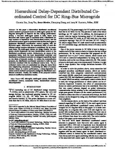
The first experiment is meant to highlight the effectiveness of the hierarchical controller design. It is performed by applying drastic load changes determined by 𝑅 for 𝑡 < 2.6 s { { { {50%𝑅 = 14 Ω for 2.6 ≤ 𝑡 < 3.8 s, 𝑅𝑚 = { { 𝑅 for 3.8 ≤ 𝑡 < 5 s, { { 21%𝑅 ≈ 5.9 Ω for 𝑡 ≥ 5 s. {
(49)
The corresponding results are shown in Figure 6. It is clear that the mechanical variable 𝜔 follows the desired trajectory 𝜔∗ , which shows the effectiveness of the designed hierarchical controller under abrupt changes of 𝑅. In Figure 6, it can be observed that smaller values than the nominal value of 𝑅 cause a significant increase of 𝑖. On the other hand, changes of 𝑅 higher than 100% from its nominal value are not
10
Mathematical Problems in Engineering
20
12
15
(V)
(rad/s)
8 10
4 5
0
0 0
1
2
3 t (s)
4
5
0
6
𝜔∗ 𝜔
1
2
3 t (s)
4
5
6
1
2
3 t (s)
4
5
6
𝜗 𝜐
0.3
0.8
0.6 (A)
0.2
0.4 0.1 0.2
0
0 0
1
2
3 t (s)
4
5
6
0 uav
i
Figure 10: Experimental results for 𝐽𝑚 .
considered, as the current would decrease, implying that less is demanded of the system. The proposed hierarchical controller is also experimentally robust with respect to the main power source, which can be observed by setting the following experimental changes: 𝐸 { { 𝐸𝑚 = {57.7%𝐸 = 30 V { {𝐸
for 𝑡 < 2.6 s, for 2.6 ≤ 𝑡 < 3.8 s, for 𝑡 ≥ 3.8 s.
(50)
Figure 7 shows the experimental behavior of the mechanical and electrical variables of the system when abrupt changes occur in 𝐸. It can be observed that the trajectory tracking task is successfully performed, since 𝜔 → 𝜔∗ . On the other hand, if the primary power supply were to change to a value higher than 𝐸, it would be observed that 𝑢av → 0, implying that less
is demanded of the system; therefore such changes were not executed. Moreover, Figure 8 shows that the trajectory tracking task is successfully performed according to the design goal, even when the system has significant abrupt changes in 𝐿 and 𝐶. The experimental changes proposed in this work are defined by 𝐿 { { 𝐿 𝑚 = {200%𝐿 = 9.88 mH { {𝐿
for 𝑡 < 2.6 s, for 2.6 ≤ 𝑡 < 3.8 s, for 𝑡 ≥ 3.8 s.
𝐶 { { { {150%𝐶 ≈ 334.4 𝜇F 𝐶𝑚 = { { 𝐶 { { {50%𝐶 = 112.2 𝜇F
for for for for
𝑡 < 2.6 s, 2.6 ≤ 𝑡 < 3.8 s, 3.8 ≤ 𝑡 < 5 s, 𝑡 ≥ 5 s.
(51)
Mathematical Problems in Engineering
11
Likewise, experimental emulation of the viscous friction coefficient was tested in the system and the results are shown in Figure 9. The proposed changes are 𝑏 { { { {500%𝑏 𝑏𝑚 = { { 𝑏 { { 800%𝑏 {
for for for for
𝑡 < 2.6 s 2.6 ≤ 𝑡 < 3.8 s, 3.8 ≤ 𝑡 < 5 s, 𝑡 ≥ 5 s.
References (52)
Finally, Figure 10 presents the results when the motor inertia is drastically changed in accordance with the following expression: 𝐽 { { 𝐽𝑚 = {141.7%𝐽 { {𝐽
for 𝑡 < 2.6 s, for 2.6 ≤ 𝑡 < 3.8 s, for 𝑡 ≥ 3.8 s.
work was partially supported with funds from the Fondo Mixto de Fomento a la Investigaci´on Cient´ıfica y Tecnol´ogica CONACYT-Gobierno del Estado de Puebla.
(53)
4. Conclusions Motivated by the hierarchical control approach applied in mobile robotics, this paper presented the experimental validation of a hierarchical controller, based on differential flatness, for the angular velocity trajectory tracking problem of a DC/DC Buck converter-DC motor system. The hierarchical controller was composed of two controls: the first one was designed for the DC motor and the second one was dedicated to the DC/DC Buck converter. Then, these controls were interconnected emulating the approach used in mobile robotics. According to the experimental results herein reported, here, the angular velocity trajectory tracking task, associated with a DC motor driven by a DC/DC Buck converter, was successfully achieved by the proposed hierarchical controller. Moreover, it showed robustness against the uncertainties associated with several system parameters. Finally, it is worth mentioning that, in practice, these kinds of changes happen neither simultaneously nor in such extreme conditions with respect to their nominal values. Nevertheless, these experiments were meant to validate the effectiveness of the proposed controller, thus presenting a glimpse of its possible future industrial applications.
Conflict of Interests The authors declare that the research was conducted in the absence of any commercial, financial, or personal relationships that could be construed as a potential conflict of interests.
Acknowledgments R. Silva-Ortigoza acknowledges financial support from Secretar´ıa de Investigaci´on y Posgrado del Instituto Polit´ecnico Nacional (SIP-IPN), SNI-Mexico, and the IPN programs EDI and COFAA. The work of C. M´arquez-S´anchez and M. Antonio-Cruz was supported by CONACYT-Mexico and PIFI scholarships. G. Salda˜na-Gonz´alez acknowledges the Fondo Mixto CONACYT, since the publication of this
[1] S. E. Lyshevski, Electromechanical Systems, Electric Machines, and Applied Mechatronics, CRC Press, Boca Raton, Fla, USA, 1999. [2] F. Antritter, P. Maurer, and J. Reger, “Flatness based control of a Buck-converter driven DC motor,” in Proceedings of the 4th IFAC Symposium on Mechatronic Systems, pp. 36–41, RuprechtKarls-University, Heidelberg, Germany, September 2006. [3] J. Linares-Flores and H. Sira-Ram´ırez, “A smooth starter for a DC machine: a flatness based approach,” in Proceedings of the 1st International Conference on Electrical and Electronics Engineering, pp. 589–594, Acapulco, Mexico, September 2004. [4] J. Linares-Flores and H. Sira-Ram´ırez, “Sliding mode-delta modulation GPI control of a DC motor through a Buck converter,” in Proceedings of the 2nd IFAC Symposium on System, Structure and Control, pp. 405–409, Oaxaca, Mexico, December 2004. [5] J. Linares-Flores and H. Sira-Ram´ırez, “DC motor velocity control through a DC-to-DC power converter,” in Proceedings of the 43rd IEEE Conference on Decision and Control, pp. 5297– 5302, Atlantis, The Bahamas, December 2004. [6] J. Linares-Flores, Control suave de velocidad de motores de CD mediante convertidores de potencia CD/CD [Ph.D. thesis], Secci´on de Mecatr´onica del Departamento de Ingenier´ıa El´ectrica del CINVESTAV-IPN, Mexico City, Mexico, 2006. [7] J. Linares-Flores, A. Orantes-Molina, and A. Antonio-Garc´ıa, “Arranque suave para un motor de CD a trav´es de un convertidor reductor CDCD,” Ingenier´ıa Investigaci´en y Tecnolog´ıa, vol. 12, no. 2, pp. 137–148, 2011. [8] H. El Fadil and F. Giri, “Accounting of Dc-Dc power converter dynamics in DC motor velocity adaptive control,” in Proceedings of the IEEE International Conference on Control Applications, pp. 3157–3162, Munich, Germany, October 2006. [9] M. A. Ahmad, R. M. T. Raja Ismail, and M. S. Ramli, “Control strategy of buck converter driven dc motor: a comparative assessment,” Australian Journal of Basic and Applied Sciences, vol. 4, no. 10, pp. 4893–4903, 2010. [10] R. Sureshkumar and S. Ganeshkumar, “Comparative study of proportional integral and backstepping controller for buck converter,” in Proceedings of the International Conference on Emerging Trends in Electrical and Computer Technology, pp. 375–379, Tamil Nadu, India, March 2011. [11] H. Sira-Ram´ırez and M. A. Oliver-Salazar, “On the robust control of Buck-converter DC-motor combinations,” IEEE Transactions on Power Electronics, vol. 28, no. 8, pp. 3912–3922, 2013. [12] R. Silva-Ortigoza, J. R. Garc´ıa-S´anchez, J. M. Alba-Mart´ınez et al., “Two-stage control design of a buck converter/DC motor system without velocity measurements via a Σ − Δ-modulator,” Mathematical Problems in Engineering, vol. 2013, Article ID 929316, 11 pages, 2013. [13] R. Silva-Ortigoza, V. M. Hern´andez-Guzm´an, M. AntonioCruz, and D. Mu˜noz-Carrillo, “DC/DC Buck power converter as a smooth starter for a DC motor based on a hierarchical control,” IEEE Transactions on Power Electronics, In press.
12 [14] J. Linares-Flores, H. Sira-Ram´ırez, J. Reger, and R. SilvaOrtigoza, “An exact tracking error dynamics passive output feedback controller for a Buck-Boost-converter driven DC motor,” in Proceedings of the 10th IEEE International Power Electronics Congress, pp. 1–5, Puebla, Mexico, October 2006. [15] J. Linares-Flores, J. Reger, and H. Sira-Ramirez, “Load torque estimation and passivity-based control of a boostconverter/DC-motor combination,” IEEE Transactions on Control Systems Technology, vol. 18, no. 6, pp. 1398–1405, 2010. [16] V. M. Hern´andez-Guzm´an, R. Silva-Ortigoza, and R. V. Carrillo-Serrano, Control Autom´atico: Teor´ıa de Dise˜no, Construcci´on de Prototipos, Modelado, Identificaci´on y Pruebas Experimentales, Colecci´on CIDETEC–IPN, Mexico City, Mexico, 2013, http://www.controlautomatico.com.mx/. [17] R. Silva-Ortigoza, M. Marcelino-Aranda, G. Silva-Ortigoza et al., “Wheeled mobile robots: a review,” IEEE Latin America Transactions, vol. 10, no. 6, pp. 2209–2217, 2012. [18] A. W. Divelbiss and J. T. Wen, “Trajectory tracking control of a car-trailer system,” IEEE Transactions on Control Systems Technology, vol. 5, no. 3, pp. 269–278, 1997. [19] R. Silva-Ortigoza, G. Silva-Ortigoza, V. M. Hern´andezGuzm´an, V. R. Barrientos-Sotelo, J. M. Albarr´an-Jim´enez, and V. M. Silva-Garc´ıa, “Trajectory tracking in a mobile robot without using velocity measurements for control of wheels,” IEEE Latin America Transactions, vol. 6, no. 7, pp. 598–607, 2008. [20] R. Silva-Ortigoza, C. M´arquez-S´anchez, M. Marcelino-Aranda et al., “Construction of a WMR for trajectory tracking control: experimental results,” The Scientific World Journal, vol. 2013, Article ID 723645, 17 pages, 2013. [21] H. Sira-Ram´ırez and S. K. Agrawal, Differentially Flat Systems, Marcel Dekker, New York, NY, USA, 2004. [22] H. Sira-Ram´ırez and R. Silva-Ortigoza, Control Design Techniques in Power Electronics Devices, Springer, London, UK, 2006.
Mathematical Problems in Engineering
Advances in
Operations Research Hindawi Publishing Corporation http://www.hindawi.com
Volume 2014
Advances in
Decision Sciences Hindawi Publishing Corporation http://www.hindawi.com
Volume 2014
Journal of
Applied Mathematics
Algebra
Hindawi Publishing Corporation http://www.hindawi.com
Hindawi Publishing Corporation http://www.hindawi.com
Volume 2014
Journal of
Probability and Statistics Volume 2014
The Scientific World Journal Hindawi Publishing Corporation http://www.hindawi.com
Hindawi Publishing Corporation http://www.hindawi.com
Volume 2014
International Journal of
Differential Equations Hindawi Publishing Corporation http://www.hindawi.com
Volume 2014
Volume 2014
Submit your manuscripts at http://www.hindawi.com International Journal of
Advances in
Combinatorics Hindawi Publishing Corporation http://www.hindawi.com
Mathematical Physics Hindawi Publishing Corporation http://www.hindawi.com
Volume 2014
Journal of
Complex Analysis Hindawi Publishing Corporation http://www.hindawi.com
Volume 2014
International Journal of Mathematics and Mathematical Sciences
Mathematical Problems in Engineering
Journal of
Mathematics Hindawi Publishing Corporation http://www.hindawi.com
Volume 2014
Hindawi Publishing Corporation http://www.hindawi.com
Volume 2014
Volume 2014
Hindawi Publishing Corporation http://www.hindawi.com
Volume 2014
Discrete Mathematics
Journal of
Volume 2014
Hindawi Publishing Corporation http://www.hindawi.com
Discrete Dynamics in Nature and Society
Journal of
Function Spaces Hindawi Publishing Corporation http://www.hindawi.com
Abstract and Applied Analysis
Volume 2014
Hindawi Publishing Corporation http://www.hindawi.com
Volume 2014
Hindawi Publishing Corporation http://www.hindawi.com
Volume 2014
International Journal of
Journal of
Stochastic Analysis
Optimization
Hindawi Publishing Corporation http://www.hindawi.com
Hindawi Publishing Corporation http://www.hindawi.com
Volume 2014
Volume 2014