HIERARCHICAL VISUALIZATION IN A SIMULATION-BASED EDUCATIONAL MULTIMEDIA WEB SYSTEM
Juan de Lara1,2 1
School of Computer Science, McGill University, 3480 University Street, Montreal, Canada Email:
[email protected]
Manuel Alfonseca2 2
ETS Informática, Universidad Autónoma de Madrid, Ctra. De Colmenar, km. 15, 28049 Madrid, Spain Email:
[email protected]
Keywords:
Web-based simulation, distance learning, courseware, electronics, OOCSMP.
Abstract:
This paper presents a system that generates web documents (courses, presentations or articles) enriched with interactive simulations and other hypermedia elements. Simulations are described using an object oriented continuous simulation language called OOCSMP. This language is complemented by two higher language layers (SODA-1L and SODA-2L). SODA-1L describes pages or slides, while SODA-2L builds courses, articles or presentations. A compiler (C-OOL) has been programmed to generate Java applets for the simulation models and HTML pages for the document pages. The paper focus on some new capabilities added to OOCSMP to handle different graphic detail levels of the system being simulated. Different views are shown as cascade windows, whose multimedia elements can be arranged and synchronized with the simulation execution. The new capabilities have been tested by extending a previously developed course on electronics.
1. INTRODUCTION Distance learning is ever more popular as a result of the increasing use of computers and the Internet. The growing demand is creating a need of better tools and techniques to build educational materials that can take advantage of all the possibilities offered by the Web (Schutte 1997). Higher education is moving from a teachercentered paradigm to a student-centered paradigm (Maly et al., 1997) where the student plays a more active role in the learning activity. Visual Interactive Simulation (VIS) (Campos and Hill, 1998) is an effective framework for such learning, because it simplifies theory understanding, encourages 'learning by discovery' and experimentation and makes the learning process more pleasant. Our approach is to integrate simulation tools with multimedia elements. This makes it possible to express in a richer way the knowledge being
provided, and gives the student a better comprehension of the problem: explanations by means of video, images, texts, etc. are not statically included in an HTML page, but are dynamically synchronized with the simulation execution. Using the Internet for distance education, one has the advantage that it offers common communication protocols and standards. It is also possible to install extensions in web browsers, that permit a richer interaction with the HTML pages. These extensions are called plug-ins. We use the Java Virtual Machine (Java, 2002) and VRML browsers (VRML, 2002) to make interactive simulations available in the Internet. Hierarchical thinking is a common strategy for systems modelling. Systems are usually made of subsystems, which in their turn are built by coupling other simpler components, and so forth. This procedure, which makes complex systems easier to tackle, is specially useful in electronic circuit design. To simulate such hierarchical systems, one needs to visualize the results at different levels in the
hierarchy. This approach is also appropriate from an educational point of view. This paper describes some extensions added to our system to generate web documents based on interactive simulations. The extensions make it possible to show and interact with different levels of the system being simulated. Detail levels are arranged in cascade windows and can be combined and synchronized with multimedia elements. The extensions have been tested by simulating an electronic circuit at different detail levels. This model has been added to a previously developed web course on electronics. The tool puts stress in key aspects of web development, such as maintainability, reusability, common look, etc. The paper is organized as follows: section 2 presents an overview of our system; section 3 describes the extensions added to show different detail levels (an example of an electronic circuit is presented); section 4 explains the extensions added to include multimedia elements in the detail windows; section 5 shows how the sample electronic circuit was added to the course; finally, section 6 presents the conclusions and the future work.
compact and permits some degree of interaction between the three language layers. The language and the compiler have been designed with an educational focus. Some of their features are: • •
•
•
•
2. GENERATING SIMULATION BASED WEB DOCUMENTS The OOCSMP continuous simulation language was designed in 1997 (Alfonseca et al., 1997) as an object oriented extension to CSMP (IBM, 1972), a language sponsored by IBM in the seventies and the eighties. A compiler (C-OOL) was built to translate OOCSMP code into C++ or Java applets. This approach simplifies the generation of simulation based web courses for technical and scientific subjects, containing interactive simulations. A few of these courses (gravitation, partial differential equations, ecology and basic electronics) can be accessed from:
Several forms of output display can be used by the same simulation. With our user interface, the student may modify parameters and object attributes, or sometimes add or delete objects during the simulation execution. This enhances the possibilities of student interaction and problem exploration. The user interface can be configured by means of compiler options to fit the student background. For example, to present a simulation to a naive user, the interface will be restricted to prevent the student to change model parameters. On the other hand, if the student is an expert, more possibilities can be provided to change the model, such as buttons to add or delete simulation objects. Alternative models can be designed, to be accessed from the main simulation. In this way, the teacher can plan interesting situations that arise when a parameter is changed, an object is added, etc. Multimedia elements may be included in the main simulation panel, and synchronized with the simulation execution. Thus, model behavior explanations will be presented in the appropriate moment.
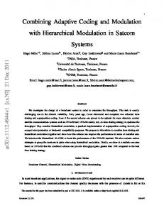
Figure 1 shows a working scheme of C-OOL when it is used to compile OOCSMP simulation models.
http://www.ii.uam.es/~jlara/investigacion Other approaches are possible, such as developing an API to a standard simulation package, but this would force the user to install such a package, which usually is not free. With our approach, the user just needs a web navigator (most of them come with a Java Virtual Machine nowadays). On the other hand, the integration of the simulation language (OOCSMP) with the page building system (SODA-1L and 2-L) makes it more
Figure 1: Working scheme of C-OOL On the left-hand side of Figure 1, MGEN is shown. This is a graphical, interactive tool written in Java that helps in the modelling of systems described by partial differential equations. This tool is able to generate OOCSMP code that can be reused in OOCSMP models.
It must also be noted that automatic documentation for the OOCSMP models is automatically obtained in the form of HTML pages. The language has been extended to produce, not only web courses, but also other kinds of documents, such as presentations and articles. For this purpose, the language was provided with two higher level layers (shown in Figure 2):
beginning of the course, the student chooses a profile, which can be changed during the navigation through the course pages. The user may also access information prepared for users with other profiles, although if these accesses occur very often, the system will suggest a permanent profile change.
•
3. EXTENSIONS TO SHOW DIFFERENT DETAIL LEVELS
•
The description of document pages is covered by a set of instructions called SODA-1L (de Lara and Alfonseca, 2001) (Simulation Course Description Language 1st Level). This set of instructions allows us to describe web documents containing hypermedia elements that are not available in plain HTML, such as simulations, two and three dimensional graphics, and maps of isosurfaces. SODA-1L forms a higher language abstraction layer than OOCSMP, because models defined in OOCSMP can be treated as hypermedia elements from the SODA-1L viewpoint. The level called SODA-2L (Simulation Course Description Language 2nd Level) can group several SODA-1L pages to build a course, a presentation or an electronic article. SODA-2L has primitives to add navigation links, headers, footnotes and indexes to the pages. These elements can be embedded in the resulting HTML pages, or added as frames. At this level, interface details that are common to all the pages are defined, which makes the SODA-1L pages very easy to reuse.
Figure 2: Our Three-Layered System Both SODA-1L and 2L are able to deal with different user profiles: texts, images and simulations can be put in the page depending on this. These profiles are set by the course designer and are fixed. The adaptive abilities are supported by technologies such as JavaScript and cookies, which run entirely on the client side (Alfonseca et al., 2001). At the
OOCSMP has different output forms that can be combined in a single problem. One of these is called a CONNECTIONPLOT and is used to generate a visual representation of the equations to be solved. This is also an input form, because the compiler generates widgets to change the values of the inputs. This output form is especially useful when the equations represent electric or electronic circuits, and has been used to generate the course on basic electronics mentioned in the previous section. The models included in the course represent electronic circuits. Complex circuits have been built by encapsulating simpler ones as block modules. In this way, 4 bit adders are modeled using 1-bit adders, which on their turn are built using basic logic gates. The new extensions added to the language make it possible to visualize different system detail levels. Our previous version of the tool only allowed to see the top level (for example, the 4-bit adder module). With the new extensions, when the user clicks on a module, an emerging window shows its internal circuits, e.g. a set of connected 1-bit adders; and so on, until we reach the bottom level, with no compound blocks. The designer of the simulation can control which levels the user can access. This is useful if the simulation is going to be presented to people with different levels of expertise. If the user is naive, the system can be tailored to show only the top level; if the user is an expert, more freedom can be given, allowing all the detail levels to be displayed. The extensions have been implemented by allowing the OOCSMP programmer to insert CONNECTIONPLOT sentences inside OOCSMP classes. Objects of classes that contain such instructions can be expanded. If a class contains several methods, the CONNECTIONPLOT instruction can have a parameter to indicate the method whose equations will be shown. These extensions will be explained with an example: a model that computes the 2-complement of a 4-bit number. To build this model, five 1-bit remainder blocks will be used, each of them made of
basic gates. Thus, the system will have three detail levels. Listing 1 shows part of the OOCSMP code that defines the 1-bit remainder modules. CLASS REST1 { ICON ic:=”rest1.gif” [64,64] ACTION A0, B0, C0 ACTION := IOR(AND(NOT(A0),EOR(B0,C0)),... C1 := IOR(AND(NOT(A0),IOR(B0,C0)),AND(... GETCARRY GETCARRY := C1 CONNECTIONPLOT ACTION }
Listing 1: Definition of a 1-bit remainder module The ICON instruction assigns an icon to the class, which will be used to represent objects in this class in the output forms that will be chosen later. In this case, the selected icon is a predefined gif file, which can be changed in subsequent constructor invocations. It also specifies the size of the graphic file in pixels. The class also defines two methods (ACTION and GETCARRY), the first is used to compute the remainder of three bits, the third one being a carry. It also computes a new carry (C1), which is returned by method GETCARRY. The last instruction in the class (CONNECTIONPLOT) lets objects of this class to be expanded. This instruction may specify the method that must be shown (ACTION in our case). If the parameter is not given, the method to be shown is the DYNAMIC (which is the main simulation loop of the class). The OOCSMP basic logic blocks IOR, AND, NOT, etc. have associated predefined icons that will be used for this representation. In the next step, a complementer is defined, using objects of class REST1. The OOCSMP code is shown in listing 2. As before, a predefined icon is declared, followed by 5 objects of class REST1. This class has a method (DYNAMIC) that connects the 1-bit remainder modules to obtain the 2-complement of the binary number represented by B0...B3. Instruction CONNECTIONPLOT is included to allow the expansion of this level. The instruction does not carry any parameters, thus DYNAMIC is the method to be expanded. The icon associated to the
REST1 objects is used to build the graphical representation. INCLUDE “REST1.csm” CLASS COMP2 { ICON ic:=”comp2.gif” [64,64] REST1 re1() REST1 re2() REST1 re3() REST1 re4() REST1 re5() DYNAMIC B0, B1, B2, B3 R0 :=re1.ACTION (0, B0 , 0 ) R1 :=re2.ACTION (0, B1 , re1.GETCARRY() ) R2 :=re3.ACTION (0, B2 , re2.GETCARRY() ) R3 :=re4.ACTION (0, B3 , re3.GETCARRY() ) R4 :=re5.ACTION (1, re4.GETCARRY(), 0 ) CONNECTIONPLOT }
Listing 2: Definition of a 4-bit complementer We also need a main simulation model, which basically has to declare some input and output variables, connect them to an object of class COMP2, set some simulation parameters and select also a CONNECTIONPLOT as the output form. Once this model is compiled with C-OOL, the applet shown in figure 3 is obtained. The background window shows the top simulation level, where the COMP2 object is represented using its associated graphical file and the inputs and outputs are shown as labeled boxes. The user can change the inputs (from 1 to 0 and vice versa) by clicking on them. The compiler generates digital or analog valued widgets appropriately. If there are several levels open (as in this case) any change to one input (or output) is propagated automatically to all the level windows. The foreground window represents the second level, showing the innards of the COMP2 object. Constants in the equations, labeled as “CONST”, are shown in blue and cannot be changed. If the user should not be able to open the detail windows, the programmer just has to remove the CONNECTIONPLOT instructions inside the classes (in Listings 1 and 2). In the future, this will be done automatically, as it is possible to define different user levels in the SODA-2L language.
Figure 3: A moment in the simulation, the first two levels are shown.
4. ADDING MULTIMEDIA TO THE DETAIL WINDOWS In previous versions of the language, it was possible to include multimedia elements (video, audio, dynamic text and images) in the main simulation window. The video and audio elements were implemented using the Java Media Framework (JMF) (JMF2.0, 2002). These elements can be placed in the simulations by including one or several instructions (VIDEOPANEL, AUDIOPANEL, TEXTPANEL or IMAGEPANEL) in the main simulation program. These instructions have parameters to synchronize the presentation of the multimedia elements with the simulation execution. Different texts or images can be shown, depending on the values of OOCSMP expressions. In this way, explanations are given to the student in the correct instant, when something is happening in the simulation, in a richer way than with static HTML pages. The new extensions let us place multimedia elements in detail windows. This is useful, because sometimes explanations specific to the detail windows have to be given. To implement these extensions, no change in the language grammar was needed, it was enough to
allow the programmer to include the multimedia instructions inside a class. The programmer can arrange different panels in a detail window, which is theoretically divided into a 3x3 grid. Thus one can place at most 9 different panels in each detail window (CONNECTIONPLOTs or multimedia elements), although the latter can also be shown in separate windows. Their position is specified in the first parameter of these instructions, which can take the values N, S, E, W, NW, SW, NE, SE, C, WINDOW, or several, if a panel should occupy more than one position. For example, assume that we want to place an explanatory text and an image in the first detail level window (the foreground window in figure 3). The text will describe the construction of the electronic circuit, and the image will change depending on the user inputs and will show a scheme of the operations to be performed when computing the 2-complement. As we have a 4-bit number, we will need 16 different pictures. In this way the student will be able to compare the behavior of the circuit with the manual operations, see why the circuit works, and understand why the circuit has been built in this way. To implement these changes, we only have to change in listing 3 the last instruction of the COMP2 class (CONNECTIONPLOT), and declare some new attributes to store the parameters of the DYNAMIC section. This is necessary, because we want to use these values in the IMAGEPANEL instruction to display the appropriate image. The final code is: INCLUDE “COMP2.csm” VALUE B0, B1, B2, B3 VALUE := B0+B1*2+B2*4+B3*8 CLASS MMCOMP2 : COMP2 { DYNAMIC B0, B1, B2, B3 A0 := B0 A1 := B1 A2 := B2 A3 := B3 CONNECTIONPLOT [C,S] IMAGEPANEL [E], START (VALUE(A0,A1,A2,A3)=0),”i0.gif”, START (VALUE(A0,A1,A2,A3)=1),”i1.gif”, ... START (VALUE(A0,A1,A2,A3)=15),”i15,gif” TEXTPANEL [SE], DEFAULT “cirexpl.txt” }
Listing 3: 4-bit complementer with multimedia elements
Figure 4: A moment in the execution of the multimedia enhanced model Notice that we inherit all the simulation code from the previous module, but the DYNAMIC method is extended to store the parameters in auxiliary variables. This class also changes and adds some output forms. We have also defined a global function to calculate the decimal value of a binary number, which is used by the IMAGEPANEL output to decide the appropriate file to display at each moment. Notice that the textual explanation is static. The DEFAULT parameter makes the output display the associated file if none of the previous conditions is true (all the conditions are tested at every time step in the simulation). In this example, where there are no previous conditions, the text never changes. Figure 4 shows an instant in the execution of the previous model (embedded in a main simulation model).
5. INTEGRATING THE EXAMPLE IN THE COURSE ON ELECTRONICS In (Alfonseca et al., 2001) we described a course on electronics which was built using older versions of our tools. In this section, we show how to add the previous example to the old course. We will take advantage of the SODA-1L and SODA-2L levels to describe the course page where the example is going to be placed, and to add the page at the appropriate position in the course. We have also prepared a SODA-2L script to compile the entire course. The course page is described using the SODA1L language. SODA-1L is a label-based language that makes it possible to invoke simulations written in OOCSMP. When describing the course pages, the focus must be set on the contents, because the common features (the appearance) of all the pages are described in the upper level (SODA-2L). This level distinction improves reusability, integration and maintainability.
The SODA-1L code is similar to the examples presented in (de Lara and Alfonseca, 2001) and (Alfonseca et al, 2001). A scheme of the SODA-2L script is shown in listing 4. [1] [2] [3] [4] [5]
INCLUDE "macros.csm" INCLUDE "styles.csm" COURSE "Digital systems" BACKGROUND="WHITE" FONT TITLE TYPE="Tahoma", SIZE="+4", COLOR="BLACK" [6] AUTHOR Juan de Lara, Manuel Alfonseca [7] EMAIL
[email protected],
[email protected] [8] WEBADDRESS www.ii.uam.es/~jlara www.ii.uam.es/~alfonsec [9] FOOTNOTE “footnote.csm” [10] SIMULATIONS -noFrame -noScaleWindow noLeyenda -WIDTH= 500 -HEIGHT= 350 [11] PAGE "modules.csm" [12] PAGE "comb.csm" [13] PAGE "seq.csm" ...
Listing 4: Script to compile the course on electronics The first two lines include files with macros and styles used in the course. SODA macros show the compiler how to translate certain patterns into HTML, SODA styles are similar to those used in usual text processing applications. The third line declares that the document will be a course (it is also possible to generate presentations and interactive articles). This line and the next configure the fonts and the colors to be used in the course. Lines 5-7 declare information about the course authors. This information can be accessed by means of the SODA variables \AUTHOR, \EMAIL and \WEBADDRESS anywhere in the SODA-2L files. This makes it possible to define headers or footnotes in a general way, increasing reusability and maintainability. For example, line 8 includes a footnote (a reference to the SODA-1L file “footnote.csm”) which will appear in all the pages in the course. This footnote shows some information about the authors. As this is done using the aforementioned SODA variables, the footnote remains completely general and can be used in other courses, even those authored by other people. Lines 9-10 configure the user interface of the simulations described in OOCSMP, which are invoked from the SODA-1L pages of the course. The pages in the course are defined in lines 11 and following. This script is input to C-OOL, which compiles every page in the course, generating HTML. If one of the pages invokes a simulation, C-OOL also compiles it, generating several Java files.
In this way, adding or deleting a page from the course only means adding one line to the SODA-2L script. Navigation links between pages are included automatically, by means of the SODA-2L instruction NAVIGATION (not shown in this example), thus the rest of the script would remain unchanged. The course is accessible at the Internet in: http://www.ii.uam.es/~jlara/investigaci on/ecomm/electronica/modules.html
6. CONCLUSIONS AND FUTURE WORK This paper describes some extensions to several tools and languages that we have used to simplify the generation of Internet courses based on simulations. These extensions allow us to show different detail levels, optionally placing and synchronizing multimedia elements inside those detail levels. The extensions have been described by means of a model of a 4-bit complementer, which has been integrated with an existing course on electronics. The system saves the course designer the need to program in low level languages such as Java or HTML, putting stress in key points in web development such as maintainability, reusability, integration and easy testing. It also makes easy to enhance the web materials with multimedia elements. Adding new pages to existing courses is also simplified, as the new page is inserted in our SODA-2L script, and the links are updated automatically by the compiler. Due to technological and cultural changes, teachers will put more and more materials and courses on the web. Most teachers are not experts in Web programming. In this context, our system is very useful, and in fact it is being used in several teaching innovation projects, in such diverse areas as electronic circuits or mechanics. Evaluations based on the student use and view of the courses are still to be collected in these two cases. A simplified version of the model described in section 4 has also been included in a course under development on basic computer science. The course is being developed in the framework of a teaching innovation project, sponsored by the Universidad Autónoma de Madrid. This will provide us with feedback about the student reactions. At present, we are working in a graphical modelling environment, called AToM3 (de Lara and Vangheluwe, 2002), (A Tool for Multi-Formalism and Meta-Modelling). That is, we can model in different formalisms, and also define the formalisms
themselves. This flexibility will permit building both simulation models and HTML pages in a graphical way. This would simplify the design of the courses and the selection and inclusion of multimedia elements. We also intend to automate the decision of opening new detail levels during the simulation. This decision will be made depending on the profile assigned to the user. Details about user profiles are defined in the SODA-2L language layer. We are also working on an OOCSMP interpreter, with the aim of letting the student to make changes in the simulation models at run time, thus extending the possibilities of experimentation. In our example, changes to the electronic circuits could be made on the fly.
7. ACKNOWLEDGMENTS This paper has been sponsored by the Spanish Interdepartmental Commission of Science and Technology (CICYT), project number TEL19990181
REFERENCES Alfonseca, M., Pulido, E., Orosco, R., de Lara, J. 1997. "OOCSMP: an object-oriented simulation language". ESS'97, Passau, pp. 44-48. Alfonseca, M., de Lara, J., Ortega, A. 2001. "Developing Adaptive Web Courses Based on Simulation: A Thick Client Approach". EUROMEDIA'01. Valencia. April 2001. Campos, A.M.C., Hill D.R.C. 1998. “An Agent-Based Framework for Visual-Interactive Ecosystem Simulations”. TRANSACTIONS of the SCS International 15, 4: 139-152. de Lara, J., Alfonseca, M. 2001. “Constructing Simulation-Based Web Documents”. IEEE Multimedia, Special Issue on Web Engineering, January-March 2001, pp. 42-49 de Lara, J., Vangheluwe, H. 2002. “AToM3: A Tool for Multi-Formalism and Meta-Modelling”. In Proceedings of Fundamental Approaches to Software Engineering, FASE’2002. Lecture Notes in Computer Science, Springer. To Appear. See also the AToM3 home page: http://moncs.cs.mcgill.ca/MSDL/research /projects/AtoM3.html IBM Corp. 1972. Continuous System Modelling Program III (CSMP III) and Graphic Feature (CSMP III
Graphic Feature) General Information Manual. IBM Canada, Ontario, GH19-7000. Java home page: http://java.sun.com Java Media Framework home page: http://java.sun.com/products/java-media/jmf/2.0 Maly, K., Overstreet, C.M., González, A., Denbar, M., Cutaran, R., Karunaratne, N., Srinivas., C. J. 1997. “Use of Web Technology for Interactive Remote Instruction”. Proceedings of the Web’97 Conference. In Internet at : http://www7.scu.edu.au/programme/posters/1855/com 1855.htm Schutte. 1997. “Virtual Teaching in Higher Education: The New Intellectual Superhighway or Just Another Traffic Jam?”. http://www.csum.edu/sociology/virexp.htm
VRML97 Specification in Internet at: http://www.web3d.org/Specifications/VRML97