The proposed address generation (AGEN) unit operates with a modified version of the low-order-interleaved mem- ory access approach. Our design supports ...
High-bandwidth Address Generation Unit Humberto Calder´on, Carlo Galuzzi, Georgi Gaydadjiev and Stamatis Vassiliadis Computer Engineering Laboratory, Electrical Engineering Dept.,EEMCS, TU Delft, The Netherlands Email:{H.Calderon,C.Galuzzi,G.N.Gaydadjiev,S.Vassiliadis}@ewi.tudelft.nl, WWW home page: http://ce.et.tudelft.nl
Abstract. In this paper we describe an efficient data fetch circuitry for retrieving several operands from a n-bank interleaved memory system in a single machine cycle. The proposed address generation (AGEN) unit operates with a modified version of the low-order-interleaved memory access approach. Our design supports data structures with arbitrary lengths and different (odd) strides. A detailed discussion of the 32-bit AGEN design aimed at multiple-operand functional units is presented. The experimental results indicate that our AGEN is capable of producing 8 x 32-bit addresses every 6 ns for different stride cases when implemented on VIRTEX-II PRO xc2vp30-7ff1696 FPGA device using trivial hardware resources.
1
Introduction
Nowadays, performance gains in computing systems are achieved by using techniques such us pipelining, optimized memory hierarchies [1], customized functional units [2], instruction level parallelism support (e.g. VLIW, Superscalar) and thread level parallelism [3] to name a few. These time and space parallel techniques require the design of optimized address generation units [4–7] capable to deal with higher issue and execution rates, larger number of memory references, and demanding memory-bandwidth requirements [8]. Traditionally, highbandwidth main memory hierarchies are based on parallel or interleaved memories. Interleaved memories are constructed using several modules or banks. Such structures allow distinct banks access in a pipelined manner [9]. In this paper we propose an AGEN for efficient utilization of n-way-interleaved main memory containing vector data, e.g. supporting kernels like SAD (sum of absolute differences) and MVM (matrix-vector multiply) operations. More specifically, the main contributions of this paper are: – An AGEN design capable of generating 8 x 32-bit address in a single cycle. In addition, arbitrary memory sequences are supported using only one instruction. – An organization that uses optimized Boolean equations to generate the 8 offsets instead of an additional adders stage.
2
– An FPGA implementation of the proposed design able to fetch 1.33 Giga operands per second from an 8-way-interleaved memory system using only 3% of the targeted device. The remainder of this paper is organized as follows. Section 2 outlines the necessary background on interleaved-memory systems. Section 3, presents the considered vector architecture, the memory interleaving mechanism and the design of the AGEN Unit. In Section 4, we discuss the experimental results in terms of used area and latency. Finally, in Section 5 conclusions and future work are presented.
2
Background
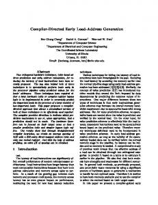
The use of multiple memory banks for providing sufficient memory bandwidth is the key element when memory system performance is evaluated [10]. The accessing of consecutive data elements separated by a fixed addressing distance is called a stride. The stride describes the relationship between the operands and their addressing structure. A memory organized with several banks which store elements in a stride manner is called an interleaved memory [11, 12]. Given that an n-bit address memory field can be divided into 1) memory-unitnumber and 2) address in memory unit (memory-address), two main addressing techniques arise from this basic address division as depicted on Figure 1. (a) High interleaved addressing mapping utilizes the low address bits v as memory-address in the unit, while the higher bits u represent the memoryunit-number. This technique is used by the traditional scalar processors with multiple memory pages. (b) Low interleaved memory mapping use the low address bits u to point out the memory-unit-number, while the higher memory bits v are the memoryaddress. u Memory Unit Number
v Address in a memory unit
(a) High Interleaved address mapping
v
u
Address in a memory unit
Memory Unit Number
(b) Low Interleaved address mapping
Fig. 1. Interleave memory formats.
The data in low-interleaved-address mapping is distributed in a round-robin like fashion among the memory banks. For example, in the memory system with 8 banks and data structure with stride =1, as presented in Figure 2, word 0 is stored in bank 0, word 1 is stored in bank 1. In general, word x is located in bank x MOD 8. In this figure, one Major Cycle (memory latency) is subdivided in 8 Minor Cycles. The retrieving of 8 consecutive elements will take one Major Cycle and 7 additional Minor Cycles. This is due to the fact that the eight consecutive elements from the memory banks are retrieved in parallel. Those read values are stored in intermediate data registers from which are issued to
3
the functional units in a pipelined manner (using 7 additional Minor Cycles). With this memory architecture the retrieving of x single-word elements will take Major Cycle + (x − 1) Minor Cycles. Minor Cycle R0
Word 0
R8
Word 8
R9
R1
Word 1
Word 9 R2
Word 2
Word 4
Word 6
Word 17
Word 47
Bank 0
Word 33
Word 40
Word 48
Bank 1
Word 26
Word 34
Word 41
Word 49
Bank 2
Word 27
Word 34
Word 42
Word 50
Bank 3
Word 28
Word 35
Word 43
Word 51
Bank 4
Word 29
Word 36
Word 44
Word 52
Bank 5
Word 30
Word 37
Word 45
Word 53
Bank 6
Word 31
Word 38
Word 46
Word 54
Bank 7
Word 25 R18
Word 18
Word 11
Word 19
R4
R12
Word 12
Word 20 R13
Word 13
Word 21
R6
R14
Word 14
Word 22
R7
Word 7
Major Cycle
Word 39
R17
R5
Word 5
Read of Word 24
Word 32
R11
R3
Word 3
Word 24
R10
Word 10
R24
R16
Word 16
Word 15
R15
Word 23
Fig. 2. Interleaved memory pipelined access to memory
3
AGEN Unit design
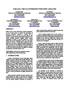
We consider a vector co-processor consisting of a group of reconfigurable functional units [13, 14] coupled to a core processor. Figure 3 presents this organization. An arbiter is used to distribute the instructions between the vector unit and the scalar processor following the paradigm proposed in [15]. Please note that many current platforms implement similar approaches, e.g. the Fast Simplex Link interface and the Auxiliary Processor Unit (APU) controller for MicroBlaze and PowerPC IP cores [16]. The memory banks presented in Figure 3 are built using dual ported memories, e.g. BRAMs [17] in case of FPGA implementation, shared by both processors, the scalar and the vector. One port of the BRAM is used by the scalar processor as a linear array memory organization with high interleaved address mapping. The second port is used by the vector unit. The memory access from the vector processor side requires dedicated AGEN unit (different from the one embedded into the core processor) that generates the addresses for the 8-way interleaved memory organization in the correct sequence order. The vector data is distributed in an interleaved-way, scattered by the stride values, that requires 8 different addresses for each memory access. The AGEN unit is configured to work with single or multiple groups (with the same stride) of streamed data using a single instruction. The AGEN special instruction configures the base addresses, the stride and the length of the particular streaming data format. The memory accesses can be performed in parallel with the execution phase of a previous iteration using the decoupled approach as presented in [2].
4 Instruction bus
Data bus
Control bus Vector Hardware Vector Vector Register Accelerators Register Register Files Files Files N - way Bus Vector Register Vector Vector Register Files Register Register Files Files Files
Arbiter
Control N-way Bus Swith
CORE
N-way Bus
PROCESSOR
Address Generation Unit
addresses
Memory Memory Memory Banks Memory Banks Memory Banks Memory Banks Memory Banks Banks Banks
8-way interleaved
Fig. 3. Block diagram of the reconfigurable Custom Computing Unit
3.1
Memory-interleaving mechanism
In this paragraph the mechanism to retrieve n data elements in parallel is presented. Figure 4, shows eight different stride cases, with odd strides ≤ 15 for eight memory banks. For example, the stride shown in case (b), is three. One can see, that in all of the cases the data is uniformly distributed in the memory banks. This fact suggests the feasibility of an AGU capable to generate the effective addresses of n data elements every major cycle. This can be formally stated as follows: n data elements stored in n memory banks can be retrieved in a single major cycle if the stride is an odd integer and n is a power of two. Otherwise stated this can be extended as follows: n data elements stored in n memory banks can be retrieved in a single major cycle if gcd(n,Stride)=1.
Fig. 4. Example of 8-way interleaved memory banks with odd strides ≤ 15.
The notation gcd(a, b) is used for the greatest common divisor. Two integers a, b are relatively prime if they share no common positive factors (divisors) except
5
of 1, e.g gcd(a, b) = 1. Extension to the general case: Let’s consider n banks of memory each holding m memory cells. The m×n memory array can be represented as a matrix [m×n] where each column corresponds to a memory bank. In addition, the cell i of the memory bank j corresponds to the matrix element with indexes (i, j). We denote this matrix as A and consider n = 2h and m for its dimensions, with h, m ∈ N. In addition, the stride of the data structures stored on the memory is an integer Str = 2q + 1, q ∈ N. From now on, the data stored in the memory banks will be considered as matrix A elements. Let the n consecutive data elements placed in different memory banks be denoted by: a0 , ..., an−1 . (1) Remark 1. Every element aα , with α = 0, ..., n − 1, is identified in the matrix by its row-index i, with i = 0, 1, ..., m − 1, and its column-index j, with j = 0, 1, ..., n−1. This means that there exists a one-to-one relation among aα and the indexes couple (iα , jα ). Additionally, the couple (iα , jα ) can be used to represent aα as a number in base n, obtainable as juxtaposition of iα as most significant digit and jα as least significant digit. The two indexes can also be used in a base 10 representation. Therefore, we have the following chain of equivalent representations for aα : aα ↔ (iα , jα ) ↔ (iα jα )|n ↔ (niα + jα )|10 .
(2)
As an example, Table 1 shows the chain of representations as defined in (2) for a case where n = 8 and Str = 3. Table 1.
Correspondence aα ↔ (iα , jα ) ↔ aα|n ↔ aα|10 for n = 8 and Str = 3.
Element aα
Row-Index iα
Column-Index jα
a0
0
0
00
0
a1
0
3
03
3
a2
0
6
06
6
a3
1
1
11
9
a4
1
4
14
12
a5
1
7
17
15
a6
2
2
22
18
a7
2
5
25
21
aα|8 aα|10
Remark 2. Without loss of generality, we can assume that the first element a0 stored in the matrix remains at position (i0 , j0 ) = (0, 0). Lemma 1. The number of rows necessary to hold n elements with stride Str = 2q + 1, q ∈ N is Str. Proof. The number of cells (♯cell ) necessary to store n elements with stride Str is ♯cell = n + (Str − 1) n = n(2q + 1). Therefore, the number of rows is ♯cell
mod n = n(Str) mod n = Str.
(3)
6
� Remark 2 and Lemma 1 imply that the necessary rows to store the n elements with stride Str are: {0, 1, ..., Str − 1} (4) The n data aα can be defined recursively. If a0 = (i0 , j0 ) the elements a2 , ..., an−1 can be recursively defined as follows: aα = aα−1 + Str.
(5)
Theorem 1. Let n be the number of elements aα , with α = 0..n − 1, stored in a matrix A, m × n, with n = 2h . Let the stride be the integer Str ∈ N. If (iα , jα ) and (iβ , jβ ) are the couples of indexes identifying aα and aβ in the matrix and gcd(n, Str) = 1, we have: jα 6= jβ ∀α, β ∈ [0, ..., n − 1].
(6)
Proof. Without loss of generality, by Remark 2, we can assume (i0 , j0 ) = (0, 0). By contradiction let jα = jβ . We have two possible cases: (1) iα = iβ and (2) iα 6= iβ . The first case is not possible: more precisely, if iα = iβ will lead to aα = aβ since jα = jβ (see Remark 1). In the second case: iα 6= iβ . Firstly, by (4), it follows: iβ − iα ∈ [0, Str − 1].
(7)
Without loss of generality we can assume β > α. By (5) we have: aβ = aβ−1 + Str = aβ−2 + 2Str = ... = aα + xStr,
(8)
with x ∈ N and x < n; it is straightforward to show that x = β − α. By using the representations in base 10 of aα and aβ (see (2)), the equation (8) becomes: niβ + jβ = niα + jα + xStr,
(9)
taking into account the assumption jα = jβ we can rewrite (9) as n(iβ − iα ) = x Str.
(10)
Since gcd(n, Str) = 1 and n divides the product x Str, it follows that n is a divisor of x. This implies that: x = r n, with r ∈ N. Therefore x > n which contradicts the original hypothesis. As a consequence, it must be that jα 6= jβ , for all α, β ∈ [0, ..., n − 1]. � Remark 3. The previous theorem can be reformulated saying that if n data elements are stored in n memory banks with a fixed stride Str and the gcd(n, Str) = 1, each data element is stored in a different memory bank.
7
Corollary 1. By Theorem 1 it follows that the data are stored in different memory banks if n = 2h and Str is an odd integer and viceversa if n is an odd integer and Str = 2h . Example: Let’s consider the case (b) presented in Figure 4. In this example, n = 8, the Str= 3. This is also the case considered in Table 1. Column 3 of Table 1, shows that each element of this data structure belongs to a different column and therefore to a different memory bank. This follows by Theorem 1. If there exist two elements aα , aβ with the same column index then there exists x < 8 such that: n(iβ − iα ) = x(2q + 1) (q = 1 in this case). Considering that n = 8 in our example, n(iβ − iα ) can be either 8 or 16. The difference cannot be 0 since in that case iα = iβ and therefore aα = aβ . As a consequence, we have two cases 8 = 3x or 16 = 3x and both equations don’t have an integer solution for x. 3.2
The AGEN Design
As stated in [18] effective address computation is performance-critical. The AGEN unit described in this section generates eight addresses for fetching data elements simultaneously from an 8-way interleaved memory system at high speed. The AGEN is designed to work with multi-operand units [13, 14] and uses a special-purpose-instruction such as the ones presented in [19]. In Figure 5 an example of such instruction is presented. The multiple base addresses in this instruction are necessary for cases with multiple indices such as SAD and MVM operations. 0
8
12
16
20
24
28
31
Fig. 5. Compound Instruction
The 4-bit instruction fields depicted in Figure 5, define the registers containing the addresses and/or the length and the stride parameters of the data structure to be accessed. More precisely they are: – Basei (i = 1, 2, 3). These registers contain the memory addresses that point to the first elements of an data arrays to read or write in the interleaved memory organization. For example, the minuend and subtrahend in the sum of absolute differences (SAD) instruction or multiplicand, multiplier and addendum in multiply-accumulate (MAC) operations. – Length. This register holds the number of n-tuples (cycles) needed to gather y-elements from the memory. For example, when length value is 10 and n = 8, 80 elements will be retrieved in 10 memory accesses. – Stride. This register holds the distance between two consecutive data elements in an n-way interleaved memory. In our case the possible strides are odd numbers in the range between 1 and 15. Thus, strides are expressed as 2q + 1, with 0 ≤ q ≤ 7. In our design, these eight possible stride values are encoded using three bits. – Index. The address stored in this register has two uses:
8
• The register contains the vertical distance between two consecutive groups of n elements. For example, Figure 4 (a) presents the index (also referred as vertical stride) that is equal to 9. • Sometimes the AGEN can be used to retrieve a single data word. In this case the register value is used as an offset address. Equation (11) describes the effective address (EA) computation. EA is obtained by the addition of a pre-computed base-stride (BS) value, the index (IX) value and the memory-bank offsets represented by Ai(0...3). Figure 6(e) depicts the 8 x EA generators for the targeted 8-way interleaved memory system.
EAi = BS + Ai(0...3) + IX
∀ 0 ≤ i ≤ 7 ∧ RES ≥ 0
Hardwired Encoder “Digitwise Strider” Adder
Subtractor
Register
Register
3/2 counter array 2/1 adder
3/2 counter array 2/1 adder
3/2 counter array 2/1 adder
(11)
Adder Register
3/2 counter array 2/1 adder
3/2 counter array 2/1 adder
3/2 counter array 2/1 adder
3/2 counter array 2/1 adder
3/2 counter array 2/1 adder
Fig. 6. Address Generation Unit: (a) Accumulator for BS computing, (b) Accumulator for loop control, (c) Hardwired encoder, (d) Index Accumulator, (e) Final addition Effective Address computing
The first addendum term (BS) of equation(11) is computed using the following relation: BS = Base + k.Stride. During the first cycle, BS is equal to the base address, therefore a 0 value is used for the second term. Thereafter, the stride offset is added for each k iteration. Note that the stride value is equal to the offset between two consecutive data elements in the same column (see also Figure 4). In Figure 6(b) the subtractor used for counting the number of memory accesses is presented. In each clock cycle, e.g. equivalent to 8 iterations of an unrolled loop, the subtractor value is decremented by one until it reaches zero. A negative value of the subtractor result (underflow) asserts the “Int” flag, indicating the end of address generation process. Figure 6(c) represents the hardwired logic for computing the offset-value Ai(0...3) which will be discussed in address transformation subsection in more details. Finally, Figure 6(d) shows the IX computation. The accumulator structure presented in Figure 6 (a) is composed by two stages partially (4-bits only) shown in Figure 7. The first stage consists of an 4/2 counter which receives the SUM and the Carry signals of the previously
9
computed value. The other two inputs (shown left on the figure) receive the muxes outcomes used to select the appropriate operands (base and stride values) as explained above. The second stage consist of a 2/1 adder that produces the BS values.
Fig. 7. Main accumulator circuitry
Address transformation: The stride values supported by our implementation are encoded using 3 bits represented by S2 S1 S0 . The pattern range 0002 ..1112 encodes the 2q + 1 stride values with 0 ≤ q ≤ 7. A hardwired logic is used to transform the encoded stride values into the corresponding A0(0...3) ,.., A7(0...3) address offsets using a memory-bank-wise operation. A “memory-bank-wise” address is created based on the stride value. For example, consider Figure 4 (c) that presents the case for stride = 5. In this case, concerning banks 1 and 4 offset values of 3 and 2 are required. These correct memory-bank-wise values are generated by our hardwired logic. Please note that our approach supports all possible odd stride values in the range between 1 and 15. The exact transformations are presented as a set of equations in Table 2. Table 2. Hardwired Encoder - Set up Table of Equations Bank
A0
A1
A2
0
0
0
0
0
1
S2 · S1 · S0 + S2 · S1 · S0 +
S2 · S1
S2 · S0 + S1 · S2
S2 · S1
S2 · S1 · S0 + S2 · S0 +
S2 · S1 · S0
S2 · S0
A3
S2 · S1 · S0 + S2 · S1 · S0 2
S1
S2 · S1 3
S2
S2 · S0
S2 · S1
S2 · S1
4
S0
S1
S2
0
5
S2
S2 · S0
6
S1
S2 · S1 + S2 · S0 +
S2 · S1 · S0 + S2 · S1 · S0 S2 · S1 · S0 S2 · S1 · S0
S2 S1 S0
S2 · S1 + S2 · S0
0
S2 · S1 · S0 7
S2 · S1 · S0 + S2 · S1 · S0 +
S2 · S1
S2 · S1 · S0 e.g. the address bit A2 for bank 1 will be: A2 = S2 · S0 + S1 · S2 . This value (offset) is added to the current Base address value for obtain EA
10
4
Experimental Results Analysis
The proposed address generation unit was described using VHDL, synthesized and functionally validated using ISE 7.1i Xilinx environment [20]. The target device used was VIRTEX-II PRO xc2vp30-7ff1696 FPGA. Table 3 summarizes the performance results in terms of delay time and hardware utilization of the complete AGEN unit as well as the major sub-units used in our proposal.
Table 3. The Address Generation unit and embedded arithmetic units Time delay (ns) Unit
Hardware used
Logic Delay Wire Delay Total Delay Slices
Address Generation Unit
4.5
Hardwired encoder (Digitwise) ‡ 4:2 counter ‡ 3:2 counter ‡ 32-bit CPA (2/1) adder ‡
673
LUTs
1.4
6.0
1072
0.3
-
0.3
9
16
0.5
0.5
1.0
72
126
0.3
-
0.3
37
64
2.2
0.7
2.9
54
99
‡: Embedded circuitry into AGEN unit. Those are presented without I/O buffers delays.
From Table 3 it can be seen that the 32-bit CPA adder used is the most expensive component in terms of delay. The latency of this adder can be additionally improved using a deeper pipeline of the CPA as shown in [21]. This will improve the overall performance of the proposed unit but will require a deeper pipelined organization. The last is important for technologies with lower memory latency like the Virtex 4 and Virtex 5 devices [22]. The AGEN unit proposed here uses 3 stage pipeline. The first two pipeline stages correspond to the accumulator for BS computation (Figure 6(a)) and the third one to the 3/2 counter array and the final 2/1 adder. The latter forms the critical path for our implementation. The proposed AGEN reaches an operation frequency of 166 MHz. Otherwise stated, our proposal is capable to generate 1.33 Giga addresses of 32-bits (totaling 43.5 Gbps) from an 8-way interleaved memory. Concerning the silicon area used by the proposed AGEN, the total unit uses only 3 % and 4 % of the targeted device in terms of slices and LUTs respectively.
5
Conclusions
A detailed description of an efficient vector address generation circuitry for retrieving several operands from an n-bank interleaved memory system in a single machine cycle was presented. The proposal is based on a modified version of the
11
low-order-interleaved memory approach. The theoretical foundation of the proposed approach that guarantees the trivial indexing structure was also presented. Moreover, a new AGEN unit capable to work with dedicated multi-operand instruction that describes inner loops was introduced. An analysis of the latency of the proposed unit indicates that it is capable to generate 8 x 32 bit addresses every 6 ns. In addition, our design uses only 3 % of the hardware resources of the targeted FPGA device. Our future work will focus on defining the complete ISA for the embedded functional units as well as the design of a more efficient reconfigurable interconnect switch with the aim of diminishing the latency and area cost of our implementation. We are also considering the design and analysis of the complete vector facility.
References 1. Corbal, J., Espasa, R., Valero, M.: Three-Dimensional Memory Vectorization for High Bandwidth Media Memory Systems. Proceedings of the 35th Annual IEEE/ACM International Symposium on Microarchitecture, 2002. (MICRO-35) (November 2002) 149 – 160 2. Espasa, R., Valero, M.: Exploiting instruction- and data-level parallelism. IEEE Micro (September 1997) 20 – 27 3. Mamidi, S., Blem, E.R., Schulte, M., Glossner, C.J., Iancu, D., Iancu, A., M.Moudgill, S.JinturkarRoesler, Nelson, B.: Instruction Set Extensions for Software Defined Radio on a Multithreaded Processor. Proceedings of the 2005 international conference on Compilers, architectures and synthesis for embedded systems (September 2005) 266–273 4. Wijeratne, S.B., Siddaiah, N., Mathew, S.K., Anders, M.A., Krishnamurthy, R.K., Anderson, J., Ernest, M., Nardin, M.: A 9-GHz 65-nm Intel Pentium 4 Processor Integer Execution Unit. IEEE Journal of Solid-State Circuits (January 2007) 26 – 37 5. Mathew, S., Anders, M., Krishnamurthy, R., Borkar, S.: A 4-GHz 130-nm address generation unit with 32-bit sparse-tree adder core. IEEE Journal of Solid-State Circuits, (May 2003) 689 – 695 6. Kim, J., Sunwoo, M.: Design of address generation unit for audio DSP. Proceedings of 2004 International Symposium on Intelligent Signal Processing and Communication Systems, 2004. ISPACS 2004. (November 2004) 616 – 619 7. Cho, J., Chang, H., Sung, W.: An FPGA based SIMD processor with a vector memory unit. Proceedings of the 2006 IEEE International Symposium on Circuits and Systems, 2006. ISCAS 2006. (May 2006) 525 – 528 8. Hirano, K., Ono, T., Kurino, H., Koyanagi, M.: A New Multiport Memory for High Performance Parallel Processor System with Shared Memory. Proceedings of the Design Automation Conference ASP-DAC ’98 (February 1998) 333–334 9. Postula, A., Chen, S., Jozwiak, L., Abramson, D.: Automated Synthesis of Interleaved Memory Systems for Custom Computing Machines. Proceedings of the 24th Euromicro Conference (August 1998) 115 – 122
12 10. Sohi, G.: High-bandwidth Interleaved Memories for Vector Processors- a Simulation Study. IEEE Transactions on Computers (January 1993) 34 – 44 11. Hwang, K., Briggs, F.: Computer Architecture and Parallel Processing. McGrawHill (1984) 12. Seznec, A., Lenfant, J.: Interleaved parallel schemes. IEEE Transactions on Parallel and Distributed Systems (December 1994) 1329 – 1334 13. Calder´ on, H., Vassiliadis, S.: Reconfigurable Multiple Operation Array. Proceedings of the Embedded Computer Systems: Architectures, Modeling, and Simulation (SAMOS05) (July 2005) 22–31 14. Calder´ on, H., Vassiliadis, S.: Reconfigurable Fixed Point Dense and Sparse MatrixVector Multiply/Add Unit. Proceedings of the IEEE International Conference on Application-Specific Systems, Architectures, and Processors (ASAP 06) (September 2006) 311–316 15. Vassiliadis, S., Wong, S., Gaydadjiev, G., Bertels, K., Kuzmanov, G., Panainte, E.: The MOLEN Polymorphic Processor. IEEE Transactions on Computers 53(11) (November 2004) 1363–1375 16. XILINX, I.: http://www.xilinx.com/ipcenter/. (2007) 17. XILINX-LogiCore: Dual-Port Block Memory v7.0 - Product Specification. DS235 Xilinx (December 2003) 18. Sanu, M., Mark, A., Ram, K., Shekhar, B.: A 4GHz 130nm Address Generation Unit with 32-bit sparse-tree adder core. In The 11th IEEE International Parallel Processing Symposium (IPPS 97) (April 1997) 310–314 19. Juurlink, B., Cheresiz, D., Vassiliadis, S., Wijshoff, H.A.G.: Implementation and Evaluation of the Complex Streamed Instruction Set. Int. Conf. on Parallel Architectures and Compilation Techniques (PACT) (September 2001) 73–82 20. XILINX, I.: The XILINX Software Manuals, XILINX 7.1i. http://www.xilinx.com/support/sw manuals/xilinx7/ (2005) 21. XILINX-LogiCore: Adder/Subtracter v7.0 - Product Specification. DS214 Xilinx (December 2003) 22. XILINX, I.: http://www.xilinx.com/products/design resources/mem corner/. Memory Solutions (2007)