PoznaÅ University of Technology, were qualified as the best performing ..... Length. Type. Provider. S01 Poznan Hall2. 8 secs. Natural - indoor. PoznaÅ University .... [17] J. Seo, H. Wey, S. Lee, K. Sohn, âMotion information sharing mode for.
> REPLACE THIS LINE WITH YOUR PAPER IDENTIFICATION NUMBER:
TIP-09741-2012R2
REPLACE THIS LINE WITH YOUR PAPER IDENTIFICATION NUMBER: standard, in early 2011 MPEG announced a Call for Proposals (CfP) on 3D Video Coding Technology [16]. Each proposed technology had to meet the condition that a standard bitstream (either AVC-compliant or HEVC-compliant) for a single view may be extracted from the entire bitstream. In response to the CfP, over 20 proposals were submitted in two categories: backward compatible with AVC and compatible with HEVC. The proposals were ranked using subjective quality assessment of the decoded and rendered video clips. The assessments were done in a large experiment that involved 12 laboratories and over 600 viewing subjects who assessed about 2700 video clips. The results were disclosed during the MPEG meeting in Geneva in November 2011. In the HEVC-compatible class, the proposals from Fraunhofer Institute – H. Hertz Institute, Berlin, and from Poznań University of Technology, were qualified as the best performing ones. The latter proposal exploits dependencies between views and depth maps in order to increase the overall coding efficiency (similarly as in [17-19]). The 3D scene information contained in depth maps was also already used to speed up the encoder mode decision [9]. Other approaches use special techniques for depth coding [7,8]. Some of them rely on independent coding of depth that allows to use the standard coding technology for the MVD format but provides limited compression efficiency. In 2012, the standardization projects for MVD video ware developed by MPEG and by ITU-T/ISO/IEC Joint Collaborative Team on 3D Video Coding Extension Development (JCT-3V). For MVC, independent depth coding [20] was included into a standard draft [21]. A more sophisticated MVC extension for MVD is also under development [22]. The MVC-like inter-view disparitycompensated prediction was also implemented on top of the HEVC technology. The adoption of MVC coding scheme to HEVC provides coding gains similar or better than MVC gains over AVC [23]. The respective standard draft is under development [24]. In the course of these standardization activities, some new tools described in this paper were also implemented in the test models [25,26] and used as a starting point for development of 3D video coding standards. II. ASSUMPTIONS AND OVERVIEW OF THE PAPER The paper presents a detailed description of the compression technology proposed by Poznań University of Technology in the response to the call [16] of MPEG. The novelty of this proposal consists in new coding tools and in a the selection of the tools resulting from extensive experiments. Hitherto, this technology was only briefly described in an MPEG document [27] and in conference contributions [28-30] that concerned some selected aspects only. The aim of this paper is to present the entire proposed technology and the most important coding tools. Some tools have been already described in the conference papers [19,31]. For those tools only brief descriptions are given in this paper; more details can be found in the references. This paper also presents the new extensive experimental results obtained by the authors.
TIP-09741-2012R2
REPLACE THIS LINE WITH YOUR PAPER IDENTIFICATION NUMBER: III. DISOCCLUDED REGION CODING As already mentioned in Introduction, the encoded views are assumed to correspond to the camera locations that are relatively close one to each other. Therefore the views are highly correlated, and the coding tools that bring most of the compression gains are those that exploit inter-view similarities. Of course, those tools are only used in the side views and are not used for the base view that is encoded using the standard HEVC technique. Here, we are going to describe such a new tool called Disoccluded Region Coding, which was proposed by the authors in order to obtain very efficient representations of the side views [29,30]. In Disoccluded Region Coding, view synthesis is used as a primary inter-view prediction mechanism. With reference to the already encoded views and the respective depth maps, a virtual side view is synthesized in the position of the view currently being coded. For the case of 3-view coding, the side views are synthesized from the base view (Fig. 3). For view synthesis the Depth-Image-Based Rendering (DIBR) is used. It is assumed that the intrinsic and extrinsic parameters of cameras are present in the transmitted bitstream for all views. In the experiments (see Section VIII) the we have used a stateof-the-art DIBR implementation developed by MPEG in View Synthesis Reference Software [32]. In the straightforward implementation of the view-synthesis prediction, residuals of the prediction (i.e. prediction errors) are sent to the decoder. Alternatively, the omission of the residuals is signaled in the bitstream. A major drawback of such a solution is considerable yet unjustified transmission payload that either comes from the transmitted residuals or from the signaling of their presence or absence. Disoccluded Region Coding was proposed in order to omit this drawback. Its idea is based on the observation that a side view consists of two types of distinctive regions (Fig. 3): Regions that can be synthesized in the decoder from the decoded base view also usually no prediction error needs to be transmitted. Disoccluded regions that cannot be synthesized from the base view and must be transmitted in the bitstream. The locations and borders of those disoccluded regions can be estimated as a side-product of the DIBR-based synthesis of the side view. After synthesis of a side view, the pixels in an occluded region remain undefined. In a frame of a synthesized view, all pixels with undefined values can be easily detected. In that way, the locations and borders of those disoccluded regions are derived using the already transmitted base view and its depth map. This is doable in the same way both in the encoder and in the decoder. Therefore, there is no need to transmit the locations and borders of the disoccluded regions. The above-mentioned observation yields that that a side view consists of two distinctive regions: Synthesizable regions that are not transmitted but synthesized in the decoder. Disoccluded regions are transmitted in the bitstream.
TIP-09741-2012R2
REPLACE THIS LINE WITH YOUR PAPER IDENTIFICATION NUMBER: The Coding Units with some disoccluded pixels are encoded using the inter-view disparity-compensated prediction well-known from the MVC extension of the AVC [12]. Note that prediction is only applicable to the disoccluded Coding Units in the side views, i.e. to a relatively small portion of pictures. Adaptation of the CU size is an important optimization mechanism in HEVC, and it is also exploited by Disoccluded Region Coding. Roughly, the goal is to choose the numbers and sizes of the Coding Units corresponding to disoccluded regions in such a way that all those Coding Units jointly cover the shapes of disoccluded regions (see Figs. 3 and 4). Both the encoder and the decoder use the same view synthesis algorithm with the same reference views. Therefore also the CU adaptation can be performed exactly in the same way both in the encoder and in the decoder. Moreover, the positions and the sizes of the Coding Units that contain pixels from the disoccluded regions can be derived in the decoder in exactly the same way as in the encoder. Therefore, there is no need for additional signaling in the bitstream.
TIP-09741-2012R2
REPLACE THIS LINE WITH YOUR PAPER IDENTIFICATION NUMBER:
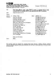
Fig. 7. High-Frequency Layer Representation in an encoder.
This estimated spatial distribution of energy is used in order to normalize the high-frequency layer. For high-frequency layer, the second component is spectral envelope. It is estimated from energy-normalized highfrequency subband using a technique similar to LPC. The resulting set of separable IIR filter coefficients (in horizontal and vertical direction) is encoded using LAR (log-area-ratio [34]) 8-bit representation. A set of those filter coefficients is estimated for each frame and transmitted to the decoder. Parameters of the noise model are highly correlated among the views. The frames of the spatial distribution of energy of all views are mapped through view synthesis to a position of the base view, and then averaged. This operation results in only one joint spatial distribution of energy (SDE). Similarly, the energy envelopes of all of the views are averaged, resulting in one joint spectral envelope.
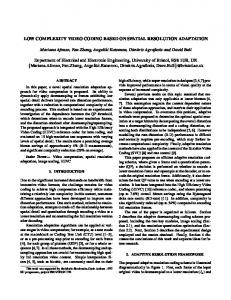
Fig. 8. Layered representation of views: low-frequency layer and Joint HighFrequency Layer Representation (SDE and LPC) – video and parameters are denoted by solid and dashed lines, respectively.
In a decoder, pseudo-random white noise is generated and then modulated by the upsampled spatial energy distribution transmitted in the bitstream and then filtered with IIR filters that reflect the envelope of the original high-frequency layer spectrum. The resultant video, which resembles the original high-frequency subband, is added to the reconstructed lowfrequency layer in order to restore the high-frequency components. V. DEPTH-BASED MOTION PREDICTION (DBMP) All of the views in a multview video sequence are projections of the same scene. Therefore, motion of the objects in the subsequent viewsis almost the same. The basic idea of this tool is to reuse motion field of the base view in the side views. The concept of DBMP was previously described in [19] for the MVC codec. Further the tool was extended [35] as a coding tool for the HEVC-based multiview video codec [36,37]. In the proposed 3D video coding technology, some
TIP-09741-2012R2
REPLACE THIS LINE WITH YOUR PAPER IDENTIFICATION NUMBER: considered as noisy, especially after classical coding which introduces uniform quantization error. This is especially disappointing for objects that reside in close distance to the camera. We propose two tools that cope with these problems: Uniform Depth Representation and Nonlinear Depth Representation. A. Consistent Depth Representation As mentioned before, the inter-view prediction based on view synthesis is widely used for both video and depth. Unfortunately, if the view synthesis algorithm uses inconsistent depth maps, it renders very annoying artifacts in the synthesized video. For that reason, the first step of the 3D video compression algorithm is the depth map inter-view consistency refinement that produces Consistent Depth Representation. The refinement technique consists of four steps: depth map smoothness improvement, depth map synthesis, inter-view depth information exchange and depth value restoration. The first step of this processing is to improve depth map smoothness by using the Mid-Level Hypothesis algorithm [38]. This algorithm increases sub-pixel precision of the artificially estimated depth maps and provides some level of alignment between the depth and the corresponding texture. This algorithm is described in more detail in [31]. The depth map synthesis is performed similarly to the view synthesis. Each depth map is synthesized from each other depth map independently. For 3-view MVD, this results in two alternative depth maps for each view. The inter-view depth information exchange consists in median filtering of alternative depth values for each view. This results in depth values that are aligned consistently in the views. The depth value restoration step ensures that the depth modifications imposed by the algorithm do not affect the overall 3D model of the scene represented by the depth maps. In general, these four steps could be repeated iteratively but the experimental results [31] indicate that the major improvement is made in the first iteration. In real-life video coding case, it is enough to do one or two iterations. B. Nonlinear Depth Representation Human perception of depth depends on absolute distance between viewed objects and the observer. A typical observer is more sensitive to depth variations close at hand than to those far away. Also, view synthesis algorithms are much more vulnerable to depth mismatch in the foreground (which results in doubling of borders of the objects) than in the background (typically resulting merely in a small displacement of the whole plane). Therefore, we propose to employ a tool called Nonlinear Depth Representation. This tool produces nonlinear representation of the depth values for compression, which consequently is equivalent to non-uniform quantization of depth. Depth samples are transformed according to a nonlinear function. An inverse transformation is done after decoding (Fig. 9). This impacts other coding and decoding operations in
TIP-09741-2012R2
REPLACE THIS LINE WITH YOUR PAPER IDENTIFICATION NUMBER:
TIP-09741-2012R2
REPLACE THIS LINE WITH YOUR PAPER IDENTIFICATION NUMBER:
TIP-09741-2012R2
REPLACE THIS LINE WITH YOUR PAPER IDENTIFICATION NUMBER: In another case - column F in Tables 2 and 3 - the synthetic noise is additionally summed with the output video (more important for subjective viewing), which improves the overall gains by about 1 percent. Such gain is not much, but also adequate to the bitrate cost of High-Frequency Layer (Fig. 13). Therefore, the main gains of the whole proposal come from: Disoccluded Region Coding, Nonlinear Depth Representation and disparity-compensated prediction (MVC-like). It is also worth noting that the remaining tools together contribute a substantial gain of approximately 2÷4% of the overall bitrate as compared to simulcast HEVC (Tables 2 and 3). The decoded stereoscopic sequences for 2-view and 3-view scenarios and bitstreams (for 8 test sequences), and decoder executables can be found at the website: http://3d-codec.multimedia.edu.pl.
A. HEVC + Nonlinear Depth Representation
B. HEVC + Disoccluded Region Coding
C. MV HEVC + Disoccluded Region Coding
D. All but Joint High-Freq.Layer Repr. switched off
E. All but high-freq. layer not added
F. Proposed codec with all tools
Test sequence S01 S02 S03 S04 Avg.
-19.6 -27.2 -29.1 -23.2 -24.8
-20.3 -55.7 -57.0 -48.8 -45.4
-26.1 -56.8 -58.0 -49.4 -47.6
-14.7 -58.0 -60.9 -54.0 -49.1
-16.9 -62.8 -61.1 -55.4 -49.1
-23.7 -59.8 -60.7 -53.7 -49.5
[2] [3] [4] [5] [6] [7]
[9] [10] [11]
[12] [13] [14]
C. MV HEVC + Disoccluded Region Coding
D. All but Joint High-Freq.Layer Repr. switched off
E. All but highfreq. layer not added
F. Proposed codec with all tools
S01 S02 S03 S04 Avg.
A. HEVC + Nonlinear Depth Representation
Test sequence
Table 3. Average bitrate reductions calculated as Bjontegaard rates for Mean Opinion Score (MOS) versus original (not preprocessed) sequences. Average (over bitrates and sequences) bitrate reduction versus HEVC simulcast
-24.5 -35.7 -8.0 -29.6 -24.5
-65.2 -67.5 -52.3 -62.0 -61.7
-67.2 -72.2 -57.4 -69.0 -66.4
-69.4 -72.6 -61.4 -68.8 -68.1
-70.1 -74.8 -62.7 -67.2 -68.7
[15]
[16] [17] [18] [19] [20]
IX. CONCLUSIONS In the paper, we have proposed a 3D video coding technology which consists of several new coding tools. The benefits and costs of individual tools have been discussed with the reference to the respective experimental results. The proposed compression technology provides bitrate reduction of the order of 60% as compared to HEVC simulcast. This figure was obtained by systematic subjective tests. It proves high compression performance of the proposed technology that allows very efficient coding of the side views. The bitrate needed for even two side views with the corresponding depth maps is mostly below 50% of the bitrate for single-view video.
9
REFERENCES [1]
[8] Table 2. Average bitrate reductions calculated as Bjontegaard rates for luma PSNR [dB] versus original (not preprocessed) sequences. Average (over bitrates and sequences) bitrate reduction versus HEVC simulcast
TIP-09741-2012R2
REPLACE THIS LINE WITH YOUR PAPER IDENTIFICATION NUMBER:
TIP-09741-2012R2