8.3.2-25
Design of Current Programmed Amorphous Silicon AMOLED Pixel Circuit B. Mazhari, Yogesh S. Chauhan Dept. of Electrical Engg. and Samtel Center for Display Technology, Indian Institute of Technology (IIT) Kanpur, India - 208016 Tel. +91–512-597924, Fax. +91-512-590063 email:
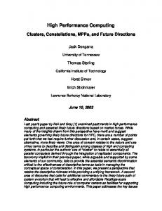
[email protected] circuits and bring out the tradeoffs between the TFT sizes and supply voltages. PIXEL CIRCUIT: ANALYSIS AND DESIGN Most current programmed AMOLED pixel circuits belong to the class of switched-current memory circuits [9]. Among the various different types of these circuits, one of them which has been used widely for AMOLED pixel design is shown in Fig. 1. Although, the switches S1-3 in the circuit are implemented using TFT1-3 , we will initially consider them to be ideal. The operation of the circuit can be divided into addressing and nonaddressing phases. In the addressing phase (S1, S2 closed and S3 open), the input programming current flows through TFT4 and also charges the capacitor CS to a suitable value of gate voltage required for the flow of this current.
ABSTRACT The present work describes in detail the design of currentprogrammed amorphous Silicon (a-Si:H) Active matrix organic light emitting diode (AMOLED) pixel circuits. The central design principle in these circuits is described and tradeoffs between TFT sizes and supply voltage elaborated. It is shown that drive currents as high as 20µA can be achieved with very good linearity. Keywords: Organic Light Emitting Diode Display, Active Matrix, Pixel driver circuit , amorphous silicon TFT circuit INTRODUCTION Organic light emitting diode (OLED) displays are being increasingly viewed as the flat panel technology of the future due to their several advantages including wide viewing angle, fast response time, thin size and low cost [13]. These displays can be built either as passive matrix panels consisting of only OLEDs or active matrix panels (AMOLED) in which the OLED is integrated with thin film transistors (TFT) in a suitable manner [4]. Passive matrix displays are simpler and cheaper but they suffer from several problems, which limit their range of applicability to low information content displays [5-6]. Although active matrix displays are more complex and expensive, they have superior characteristics and are necessary for high resolution applications. AMOLED displays can be built by integrating either amorphous Silicon TFTs [4] or Polysilicon TFTs [7]. Amorphous Silicon technology suffers from the disadvantages of small carrier mobility and the unavailability of P-type transistor but it has the advantage of being more mature and relatively cheaper as compared to Poly-Silicon TFT technology. Although currentprogrammed AMOLED displays using a-Si:H TFTs have been successfully demonstrated, they had limited current range over which the output current matched with the input programming current. In an earlier work [8] we had demonstrated that through proper TFT sizing the current range of these pixels can be increased by a factor as large as three. In the present work we present a detailed and systematic study on the design of these AMOLED pixel
Vdd
φ
S3 S2
φ CS
TFT4
S1
Idata
Fig. 1 Current Programmed pixel circuit
Because the gate voltage tracks the threshold voltage of TFT4, the effect of variation in threshold voltage is practically cancelled in this circuit. During the nonaddressing phase (S1, S2 open and S3 closed), the gate voltage on the capacitor tends to maintain the same current through TFT4 and OLED. Besides insensitivity to threshold voltage variation, another important characteristic that these current-programmed AMOLED pixel circuits must exhibit is small mismatch between the output current during the non-addressing phase and the input programming current. Ideally the relationship
327
(W/L ~1000/6) then the nonlinearity approaches less than 2%. Fig.3 (solid line) shows the effect on nonlinearity for a relatively smaller TFT3 size of 100/6 while TFT2 size is kept very large. After a certain threshold, nonlinearity increases sharply in the positive direction. Fig.3 (broken line) shows the impact on nonlinearity for TFT2 size of 100/6 while TFT3 size is now kept very large. Non-linearity again increases but in the negative direction this time. In an earlier work [8] it was reported that the major reason for sharp increase in nonlinearity was clock feedthrough effect which often plays an important role in switched-current and switched capacitor circuits. However, further investigation has revealed that non-linearity is about the same under both static and dynamic conditions, thereby discounting the clock feedthrough effects. For all the cases where nonlinearity was significant, it has been found that transistor TFT4 does not operate in saturation mode either during the addressing or non-addressing phase. In other words, nonlinearity remains small only when transistor TFT4 operates in saturation mode all the time. This is understandable because only under this condition the transistor acts as a current source whose value depends primarily on the gate-to-source voltage. The
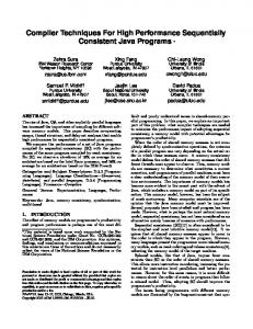
between the two current should be linear but there are a number of factors that result in non-linearity in this transfer characteristic and limit the useful current range and thereby also the gray scale in displays. To understand these factors, the circuit shown in Fig.1 was simulated with AIMSPICE simulator using the amorphous silicon TFT model (Level15 ASIA2). A Supply voltage of 25V, CS = 6pF, TFT4 size of 250µm/6µm and OLED of area 100µm x 100µm were initially assumed. The OLED model consisting of a nonlinear current source in parallel with a capacitor was chosen such that the I-V characteristics predicted by it matched well with state-of-the-art experimentally reported data. The programming period was taken to be 35µs, under what is required for VGA resolution. Fig. 2 (solid line) shows the non-linearity defined as [( I data − I out ) I data ] × 100 as a function of input
Non-linearity(%)
programming current. We assume that pixel circuits that work satisfactorily for currents as large as 20µA will be sufficient for many applications for the specified OLED area. It can be seen that the non-linearity is under 6% for current as large as 25µA. However, when the same circuit is simulated with ideal switches replaced by TFTs of sizes as reported earlier[4], then the non-linearity increases sharply with current (Fig.2 broken line) and the current range for which non-linearity is less than 5% is only 8µA. To investigate reasons for non-linearity, the circuit shown in Fig.1 was simulated with switches replaced by TFTs of different sizes. It was observed that the size of TFT1 did not play any important role as long as there is sufficient time to charge the capacitance CS. For a fixed size of TFT4 , it was observed that sizes of TFT2 and TFT3 had a large impact on nonlinearity. If sizes of both these TFTs are kept very large
Non-linearity(%)
(a)
0 -10
(b)
-20 -30 -40 0
10 0
(a)
-20
(b)
-40 5
10
15
Idata(µA)
20
10
Idata(µA)
15
20
transition of transistor TFT4 from saturation to triode region as current increases can explain the results shown in Fig.2 and Fig.3. For the case where all switches are ideal, gate and drain are shorted during the addressing phase so that transistor TFT4 operates in saturation. During the non-addressing phase, the drain voltage is equal to supply voltage and since gate voltage is less than it, TFT4 operates in saturation again. As a result non-linearity is small because M4 is in saturation all the
-30
0
5
Fig. 3 Non-linearity in Idata vs. Iout characteristics for case (a) where (W/L)2=1000µm/6µm, (W/L)3=100µm/6µm and for the case (b) where (W/L)2=100µm/6µm, (W/L)3=1000µm/6µm
-10
-50
10
25
Fig. 2 Non-linearity in Idata vs Iout characteristics for case(a) switches are ideal and case (b) switches are replaced by TFTs [(W/L)1=50µm/6µm, (W/L)2=100µm/6µm, (W/L)3 = (W/L)4 = 250µm /6µm)]
328
where both are of equal size. Under this condition, Eq.(1) allows the size of TFT4 to be computed for fixed choice of supply voltage. To obtain the precise nature of this tradeoff between TFT size and supply voltage, we use circuit simulations again. For a fixed supply voltage, the size of TFT4 is gradually increased and nonlinearity is monitored. The TFT size for which the nonlinearity falls below a specified threshold (5%) is taken as the minimum necessary size for the TFT. During these simulations, TFT2 size is kept at some large value to eliminate its effect on nonlinearity. In this manner the curves shown in Fig.4 were obtained for different values of maximum input data current. Fig.4 is very helpful in
time. When switch S3 is replaced by TFT3 of relatively small size, then during the addressing phase TFT4 operates in saturation as before. However, during the non-addressing phase, TFT4 may not operate in saturation depending on the magnitude of the current. As current increases, the voltage drop across TFT3 increases which lowers the drain voltage of TFT4. When this voltage falls below gate voltage by an amount equal to the threshold voltage, TFT4 enters triode region. The current through TFT4 now becomes sensitive to its drain-to-source voltage as well. As input current increases, the drain voltage falls leading to output current which is less than the programming current. This results in positive nonlinearity as shown in Fig.3. When only S2 is replaced by TFT of relatively smaller size, the transistor TFT4 remains in saturation mode during the non-addressing phase but may come out of saturation mode during the addressing phase. As input current increases the voltage drop across TFT2 increases which causes drain voltage to fall below the gate voltage. When this drop crosses threshold voltage, TFT4 enters triode region and the nonlinearity begins to increase. Based on these insights and using a simple MOS model, expressions can be easily derived for the constraints that must be obeyed to ensure operation of TFT4 in saturation mode during both addressing and non-addressing phases: V DD − VT − VOLED 1 1 (1) β4
β2 ≥
+
β3
≤
W4(µm)
600 400 200 0
16
20 24 VDD(V)
28
32
Fig. 4 Minimum required Size of TFT4 (TFT3) as a function of Supply voltage VDD for maximum data current varying from 530µA
max 2 I data
max I data
5 10 15 20 25 30
800
deciding the choice of supply voltage and the corresponding sizes of TFT3 and TFT4. The size of TFT2 is determined in a similar manner. For a given maximum input data current and a choice of supply voltage and TFT4 size, the size of TFT2 is gradually increased till the nonlinearity falls below the specified threshold value. Fig.5 shows the results obtained for different values of data current and supply voltages. Fig.4 and Fig.5 can now be used to design the pixel circuit for any specified
(2)
max (VDD − VT − VOLED − 2 I data β 4 )VT
max is the maximum input data where β = µCox (W / L) . I data
current for which the pixel circuit must work satisfactorily and VDD is the supply voltage. VT is the threshold voltage of TFT and VOLED is the voltage drop across OLED when max
current through it is equal to I data . Eq.(1) ensures that TFT4 operates in saturation mode in non-addressing phase and Eq.(2) ensures the same for the addressing phase. The ‘high’ value of clock voltages is also assumed to be VDD, while the ‘low’ value is taken to be zero. Although the above equations are simplistic because they are derived using a bulk MOS model, they provide useful design guidelines. For example, Eq.(1) reveals that for a specified maximum input data current and for a choice of supply voltage, there is a tradeoff between the sizes of TFT4 and TFT3 . A smaller size of TFT4 would require a larger size for TFT3 and vice-versa so that a reasonable choice is one
5 10 15 20 25 30
W2(µm)
600 400 200 0
16
20
24
28
32
VDD(V) Fig. 5 Minimum required Size of TFT2 as a function of Supply voltage VDD for maximum data current varying from 5-30µA
329
curves has been presented which allows the designer to make a suitable choice of supply voltage and TFT sizes for a specified maximum input data current. The design approach described here can be extended to Poly-Silicon TFT based AMOLED circuits as well if the kink effect is suppressed through a suitable choice of TFT4 channel length.
maximum input data current. For example, for maximum input data current of 20µA, one obtains (W/L)4 = (W/L)3 = 190/6 and (W/L)2 = 170/6. Fig. 6 shows that the match between input and output currents is excellent for this design. 25 20
REFERENCES
IOUT(µA)
15 1.
10 5 0
2.
0
5
10
15
20
Idata(µA) 3.
Fig. 6 IOUT vs. Idata transfer characteristic (solid line) for a pixel circuit designed for maximum input current of 20µA
4.
One can improve the circuit of Fig.1 through the modification shown in Fig. 7. The nonlinearity is now almost independent of size of TFT2 and it can be chosen to be as small as 50/6.
5.
Vdd
φ
6.
φ
S3
S2
7.
S1
TFT4
Idata
8.
9. Fig. 7 Improved AMOLED circuit
SUMMARY In summary, the design of a-Si:H TFT based AMOLED pixel circuit has been described in detail. A family of
330
S. R. Forrest, P. E. Burrows, and M. E. Tompson, “Organic emitters promise a new generation of displays,” Laser Focus World, vol. 31, no. 2, pp. 99-101, Feb. 1995. C. W. Tang, “An overview of organic electroluminescent materials and devices,” in Dig. Soc. For Information Display Int. Symp., 1996, vol. 27, pp. 181-184. L. J. Rothberg and A. J. Lovinger, “Status and prospects for organic electroluminescence,” J. Mater. Res., vol. 11, p. 3174-3187, 1996. Y. He, R. Hattori and J. Kanicki, “Four-thin film transistor pixel electrode circuits for active-matrix organic light emitting displays,” Jpn. J. Appl. Phys., vol. 40, p. 1199, 2001 G. Gu, and S. R. Forrest, “Design of Flat-Panel Displays Based on Organic Light-emitting Devices,” IEEE J. of Quantum Electronics, vol. 4, no. 1, p. 83, 1998. D. Braun, “Crosstalk in passive matrix polymer LED displays,” Synth. Met., 92 (1998), p. 107, 1998. Y. Hong, J. Kanicki, and R. Hattori, “Novel Poly-Si TFT pixel Electrode Circuits and Current Programmed ActiveMatrix driving Methods for AM-OLEDs,” Digest of SID’02, p.618, 2002. S.K. Bhowmik and B. Mazhari, “An improved four-TFT circuit for Active Matrix Organic Light Emitting Diode (OLED) Display,” Digest of SID’02, p.606, 2002. S.J. Daubert, D. Vallancourt, Y. Tsivids, “Current copier cells”, Electronic Letters,vol.24, no.25, p.1560, 1988.