distribution networks, and the design of on-chip decoupling capacitors. Mr. Popovich received the ...... the total current drawn from the power delivery network.
High Performance Power Distribution Networks with On-Chip Decoupling Capacitors for Nanoscale Integrated Circuits by Mikhail Popovich Submitted in Partial Fulfillment of the Requirements for the Degree Doctor of Philosophy
Supervised by Professor Eby G. Friedman Department of Electrical and Computer Engineering The College School of Engineering and Applied Sciences University of Rochester Rochester, New York 2007
ii
It has become appallingly obvious that our technology has exceeded our humanity. — Albert Einstein
iii
Dedication This work is dedicated to my parents, Mr. Evgeniy Antonovich and Mrs. Lyudmila Mikhailovna, my wife Oksana, and my daughter Elizabeth Michelle.
iv
Curriculum Vitae Mikhail Popovich was born in Izhevsk, Russia in 1975. He received the B.S. degree in electrical engineering from Izhevsk State Technical University, Izhevsk, Russia in 1998, and the M.S. degree in electrical and computer engineering from the University of Rochester, Rochester, NY in 2002, where he is completing the Ph.D. degree in electrical engineering. He was an intern at Freescale Semiconductor Corporation, Tempe, AZ, in the summer 2005, where he worked on signal integrity in RF and mixed-signal ICs and developed design techniques and methodologies for placing distributed on-chip decoupling capacitors. His professional experience also includes characterization of substrate and interconnect crosstalk noise in CMOS imaging circuits for the Eastman Kodak Company, Rochester, NY. He has authored a book and several conference and journal papers in the areas of power distribution networks in CMOS VLSI circuits, placement of on-chip decoupling capacitors, and the inductive properties of on-chip
v
interconnect. His research interests are in the areas of on-chip noise, signal integrity, and interconnect design including on-chip inductive effects, optimization of power distribution networks, and the design of on-chip decoupling capacitors. Mr. Popovich received the Best Student Paper Award at the ACM Great Lakes Symposium on VLSI in 2005 and the GRC Inventor Recognition Award from the Semiconductor Research Corporation in 2007.
Publications Book 1. M. Popovich, A. V. Mezhiba, and E. G. Friedman, Power Distribution Networks with On-Chip Decoupling Capacitors, Springer Publishing Company (in press).
Journal Papers 2. M. Popovich, R. M. Secareanu, E. G. Friedman, and O. L. Hartin, “Efficient Placement of Distributed On-Chip Decoupling Capacitors in Nanoscale ICs,” IEEE Transactions on Very Large Scale Integration (VLSI) Systems (in submission). 3. M. Popovich, M. Sotman, A. Kolodny, and E. G. Friedman, “Effective Radii of On-Chip Decoupling Capacitors,” IEEE Transactions on Very Large Scale Integration (VLSI) Systems (in submission). 4. M. Popovich, E. G. Friedman, M. Sotman, and A. Kolodny, “On-Chip Power Distribution Grids with Multiple Supply Voltages for High Performance Integrated Circuits,” IEEE Transactions on Very Large Scale Integration (VLSI) Systems (in submission).
vi
5. M. Popovich and E. G. Friedman, “Decoupling Capacitors for Multi-Voltage Power Distribution Systems,” IEEE Transactions on Very Large Scale Integration (VLSI) Systems, Vol. 14, No. 3, pp. 217–228, March 2006.
Conference Papers 6. M. Popovich, R. M. Secareanu, E. G. Friedman, and O. L. Hartin “Distributed On-Chip Decoupling Capacitors,” ACM International Conference on NanoNetworks (in submission). 7. M. Popovich, R. M. Secareanu, E. G. Friedman, and O. L. Hartin, “Efficient Placement of Distributed On-Chip Decoupling Capacitors in Nanoscale ICs,” Proceedings of the IEEE/ACM International Conference on Computer-Aided Design, November 2007 (in press). 8. M. Sotman, A. Kolodny, M. Popovich, and E. G. Friedman, “On-Die Decoupling Capacitance: Frequency Domain Analysis of Activity Radius,” Proceedings of the IEEE International Symposium on Circuits and Systems, pp. 489–492, May 2006. 9. M. Popovich, E. G. Friedman, M. Sotman, A. Kolodny, and R. M. Secareanu, “Maximum Effective Distance of On-Chip Decoupling Capacitors in Power Distribution Grids,” Proceedings of the ACM/IEEE Great Lakes Symposium on VLSI, pp. 173–179, April/May 2006. 10. M. Sotman, M. Popovich, A. Kolodny, and E. G. Friedman, “Leveraging Symbiotic On-Die Decoupling Capacitance,” Proceedings of the IEEE Conference on Electrical Performance of Electronic Packaging, pp. 111–114, October 2005. 11. M. Popovich, E. G. Friedman, R. M. Secareanu, and O. L. Hartin, “On-Chip Power Noise Reduction Techniques in High Performance SoC-Based Integrated Circuits,” Proceedings of the IEEE International SOC Conference, pp. 309–312, September 2005.
vii
12. M. Popovich and E. G. Friedman, “Noise Coupling in Multi-Voltage Power Distribution Systems with Decoupling Capacitors,” Proceedings of the IEEE International Symposium on Circuits and Systems, pp. 620–623, May 2005. 13. M. Popovich, E. G. Friedman, M. Sotman, and A. Kolodny, “On-Chip Power Distribution Grids with Multiple Supply Voltages for High Performance Integrated Circuits,” Proceedings of the ACM/IEEE Great Lakes Symposium on VLSI, pp. 2–7, April 2005 (received the best student paper award for GLSVLSI 2005). 14. M. Popovich and E. G. Friedman, “Noise Aware Decoupling Capacitors for Multi-Voltage Power Distribution Systems,” Proceedings of the IEEE International Symposium on Quality Electronic Design, pp. 334–339, March 2005. 15. M. Popovich and E. G. Friedman, “Impedance Characteristics of Decoupling Capacitors in Multi-Power Distribution Systems,” Proceedings of the IEEE International Conference on Electronics, Circuits, and Systems, pp. 160–163, December 2004. 16. M. Popovich and E. G. Friedman, “Decoupling Capacitors for Power Distribution Systems with Multiple Power Supplies,” Proceedings of the 28th Annual IEEE EDS/CAS Activities in Western New York Conference, p. 9, November 2004. 17. M. Popovich and E. G. Friedman, “Decoupling Capacitors for Power Distribution Systems with Multiple Power Supply Voltages,” Proceedings of the IEEE International SOC Conference, pp. 331–334, September 2004. 18. M. Margala, R. Alonzo, G.-Q. Chen, B. J. Jasionowski, K. Kraft, M. Lay, J. Lindner, M. Popovich, and J. Suss, “Low-Voltage Power-Efficient Adder Design,” Proceedings of the IEEE Midwest Symposium on Circuits and Systems, pp. 461–464, August 2002.
viii
Patent Disclosures 19. M. Popovich, R. M. Secareanu, E. G. Friedman, and O. L. Hartin, “Distributed On-Chip Decoupling Capacitor Network,” US patent pending. 20. M. Popovich and E. G. Friedman, “Method and Design Flow for Effective Placement of On-Chip Decoupling Capacitors Determined by Maximum Effective Radii,” US patent pending (received 2007 GRC Inventor Recognition Award from the Semiconductor Research Corporation). 21. M. Popovich, E. G. Friedman, R. M. Secareanu, and O. L. Hartin, “Method and Apparatus to Reduce Noise Fluctuations in On-Chip Power Distribution Networks,” US patent pending. 22. R. M. Secareanu, M. Popovich, W. Parmon, and O. L. Hartin, “Design of a Distributed On-Chip Decoupling Capacitor Network – Correlation between a Distributed Capacitor and Circuit Demands,” Freescale defensive patent, August 11, 2006, http://www.ip.com/pubview/IPCOM000138959D.
ix
Acknowledgments The unforgettable memory and experience that I have had at the University of Rochester will greatly embellish the rest of my life. It is impossible to acknowledge all those people who have made my life in Rochester joyful and meaningful. If your name is not listed, rest assured that my gratitude is not less than for those listed below. First of all, I would like to express my deepest appreciation to my academic advisor, Professor Eby G. Friedman, for his generous mentorship in my academic and personal growth. He was the one who gave me a chance to perform this research and believed in my success. His professionalism, commitment, and kindness have brought the best out of me. Thank you for making my research experience fruitful and highly enjoyable. I thank Professors Paul Ampadu, Michael Huang, and Daniel Stefankovic for serving on my proposal and defense committees and for their valuable advice and comments regarding this dissertation. I would also like to thank Professor David
x
H. Albonesi for his support. I would express my appreciation to the University of Rochester and the Department of Electrical and Computer Engineering for providing a unique environment which encourages high quality research. I would also like to thank all of the department secretaries and computer staff for their active support. Special thanks to Prof. Avinoam Kolodny and Michael Sotman from Technion – Israel Institute of Technology for their collaboration and support. Their generous feedback has greatly improved my work. I am grateful to Olin L. Hartin, Marie Burnham, and Radu M. Secareanu for giving me the opportunity of a summer internship in Freescale Semiconductor Corporation and for their collaboration and suggestions. I would like to thank those previous and current members in the High Performance VLSI/IC Design and Analysis Laboratory: Andrey Mezhiba, Dimitris Velenis, Volkan Kursun, Boris Andreev, Weize Xu, Magdy El-Moursy, Junmou Zhang, Guoqing Chen, Vasilis Pavlidis, Jonathan Rosenfeld, Emre Salman, Renatas Jakushokas, and Ioannis Savidis for their help, advise, and companionship. I would also like to thank RuthAnn Williams for administrative support and for giving a spark to routine life in the lab. Last, but not least, I want to thank my wife Oksana and my daughter Elizabeth for all of the support that they give me and happiness they bring to my life. I am sorry for all holidays and weekends that I missed working on my dissertation. I am deeply indebted to my parents for supporting me in every stage of my life. I owe you much of what I have become. My debt to you can never be paid. My gratitude is also
xi
extended to relatives and friends in Russia for their understanding and encouragement throughout my life. This work is supported in part by the Semiconductor Research Corporation under Contract Nos. 2003-TJ-1068 and 2004-TJ-1207, the National Science Foundation under Contract Nos. CCR-0304574 and CCF-0541206, grants from the New York State Office of Science, Technology & Academic Research to the Center for Advanced Technology in Electronic Imaging Systems, and by grants from Intel Corporation, Eastman Kodak Corporation, Manhattan Routing, Intrinsix Corporation, and Freescale Semiconductor Corporation.
xii
Abstract With the on-going miniaturization of integrated circuit feature size, the design of power and ground distribution networks has become a challenging task. With technology scaling, the requirements placed on on-chip power distribution systems have significantly increased. The higher switching speed of a greater number of smaller transistors produces faster and larger current transients in the power distribution network. These conditions place strict requirements on the on-chip power distribution network to ensure the integrity of the on-chip power supply. To manage the problem of high power dissipation, multiple on-chip power supply voltages have become commonplace in nanoscale integrated circuits. On-chip power distribution grids with multiple power supply voltages and multiple grounds are presented in this dissertation. The impedance characteristics of the power distribution grids with multiple power supply voltages and multiple grounds are described. The proposed power distribution grid structures are shown to outperform traditional power distribution grids with multiple power supply voltages and a single ground.
xiii
Decoupling capacitors are widely used to manage power supply noise. Conventional approaches for placing on-chip decoupling capacitors is shown to be ineffective in nanoscale integrated circuits. A design methodology for placing on-chip decoupling capacitors based on the maximum effective radii is described in this dissertation. Techniques to estimate the minimum required on-chip decoupling capacitance are presented. A methodology for designing decoupling capacitors for power distribution systems with multiple power supply voltages is also described. As the minimum feature size continues to scale, additional on-chip decoupling capacitance will be required to support increasing current demands. A larger on-chip decoupling capacitance requires a greater area which cannot conveniently be placed in proximity of the switching circuits. A system of distributed on-chip decoupling capacitors is shown to be a good compromise, providing the required charge drawn by the load while satisfying existing technology constraints. The research presented in this dissertation provides specific methodologies, techniques, and strategies for designing robust on-chip power distribution networks with on-chip decoupling capacitors for application to high performance nanoscale integrated circuits.
xiv
Contents Dedication
iii
Curriculum Vitae
iv
Acknowledgments
ix
Abstract
xii
List of Tables
xx
List of Figures 1 Introduction
xxii 1
1.1
The Problem of Power Delivery . . . . . . . . . . . . . . . . . . . . .
4
1.2
Detrimental Effects of Power Distribution Noise . . . . . . . . . . . .
7
1.3
Dissertation Outline . . . . . . . . . . . . . . . . . . . . . . . . . . .
10
2 Decoupling Capacitance 2.1
2.2
14
Introduction to Decoupling Capacitance . . . . . . . . . . . . . . . .
16
2.1.1
Historical Retrospective . . . . . . . . . . . . . . . . . . . . .
16
2.1.2
Decoupling Capacitor as a Reservoir of Charge . . . . . . . . .
18
2.1.3
Practical Model of a Decoupling Capacitor . . . . . . . . . . .
21
Impedance of Power Distribution System with Decoupling Capacitors
25
2.2.1
Target Impedance of a Power Distribution System . . . . . . .
26
2.2.2
Antiresonance . . . . . . . . . . . . . . . . . . . . . . . . . . .
30
xv
2.2.3 2.3
2.4
2.5
2.6
Hydraulic Analogy of Hierarchical Placement of Decoupling Capacitors . . . . . . . . . . . . . . . . . . . . . . . . . . . . .
37
Intrinsic vs Intentional On-Chip Decoupling Capacitance . . . . . . .
43
2.3.1
Intrinsic Decoupling Capacitance . . . . . . . . . . . . . . . .
44
2.3.2
Intentional Decoupling Capacitance . . . . . . . . . . . . . . .
48
Types of On-Chip Decoupling Capacitors . . . . . . . . . . . . . . . .
52
2.4.1
Polysilicon-Insulator-Polysilicon (PIP) Capacitors . . . . . . .
52
2.4.2
MOS Capacitors . . . . . . . . . . . . . . . . . . . . . . . . .
55
2.4.3
Metal-Insulator-Metal (MIM) Capacitors . . . . . . . . . . . .
66
2.4.4
Lateral Flux Capacitors . . . . . . . . . . . . . . . . . . . . .
69
2.4.5
Comparison of On-Chip Decoupling Capacitors . . . . . . . .
75
Allocation of On-Chip Decoupling Capacitors . . . . . . . . . . . . .
78
2.5.1
Charge-Based Allocation Methodology . . . . . . . . . . . . .
81
2.5.2
Allocation Strategy Based on the Excessive Noise Amplitude .
83
2.5.3
Allocation Strategy Based on Excessive Charge . . . . . . . .
85
Chapter Summary . . . . . . . . . . . . . . . . . . . . . . . . . . . .
88
3 Multiple On-Chip Power Supply Systems 3.1
3.2
90
ICs with Multiple Power Supply Voltages . . . . . . . . . . . . . . . .
92
3.1.1
Multiple Power Supply Voltage Techniques . . . . . . . . . . .
93
3.1.2
Clustered Voltage Scaling (CVS) . . . . . . . . . . . . . . . .
96
3.1.3
Extended Clustered Voltage Scaling (ECVS) . . . . . . . . . .
97
Challenges in ICs with Multiple Power Supply Voltages . . . . . . . .
98
3.2.1
Die Area . . . . . . . . . . . . . . . . . . . . . . . . . . . . . .
99
3.2.2
Power Dissipation . . . . . . . . . . . . . . . . . . . . . . . . . 100
3.2.3
Design Complexity . . . . . . . . . . . . . . . . . . . . . . . . 101
3.2.4
Placement and Routing . . . . . . . . . . . . . . . . . . . . . . 102
3.3
Optimum Number and Magnitude of Available Power Supply Voltages 107
3.4
Chapter Summary . . . . . . . . . . . . . . . . . . . . . . . . . . . . 113
xvi
4 On-Chip Power Distribution Grids with Multiple Supply Voltages for High Performance Integrated Circuits
115
4.1
Background . . . . . . . . . . . . . . . . . . . . . . . . . . . . . . . . 118
4.2
Simulation Setup . . . . . . . . . . . . . . . . . . . . . . . . . . . . . 120
4.3
Power Distribution Grid with Dual Supply and Dual Ground . . . . . 121
4.4
Interdigitated Grids with DSDG . . . . . . . . . . . . . . . . . . . . . 127
4.5
4.6
4.4.1
Type I Interdigitated Grids with DSDG . . . . . . . . . . . . 128
4.4.2
Type II Interdigitated Grids with DSDG . . . . . . . . . . . . 130
Paired Grids with DSDG . . . . . . . . . . . . . . . . . . . . . . . . . 133 4.5.1
Type I Paired Grids with DSDG . . . . . . . . . . . . . . . . 134
4.5.2
Type II Paired Grids with DSDG . . . . . . . . . . . . . . . . 136
Simulation Results . . . . . . . . . . . . . . . . . . . . . . . . . . . . 141 4.6.1
Interdigitated Power Distribution Grids without Decoupling Capacitors . . . . . . . . . . . . . . . . . . . . . . . . . . . . . 146
4.6.2
Paired Power Distribution Grids without Decoupling Capacitors 149
4.6.3
Power Distribution Grids with Decoupling Capacitors . . . . . 152
4.6.4
Dependence of Power Noise on the Switching Frequency of the Current Loads . . . . . . . . . . . . . . . . . . . . . . . . . . . 157
4.7
Design Implications . . . . . . . . . . . . . . . . . . . . . . . . . . . . 160
4.8
Chapter Summary . . . . . . . . . . . . . . . . . . . . . . . . . . . . 163
5 On-chip Power Noise Reduction Techniques in High Performance Integrated Circuits 5.1
166
Ground Noise Reduction through an Additional Low Noise On-Chip Ground . . . . . . . . . . . . . . . . . . . . . . . . . . . . . . . . . . 170
5.2
5.3
Dependence of Ground Bounce Reduction on System Parameters . . . 173 5.2.1
Physical Separation between Noisy and Noise Sensitive Circuits 174
5.2.2
Frequency and Capacitance Variations . . . . . . . . . . . . . 176
5.2.3
Impedance of an Additional Ground Path . . . . . . . . . . . 177
Chapter Summary . . . . . . . . . . . . . . . . . . . . . . . . . . . . 180
xvii
6 Decoupling Capacitors for Multi-Voltage Power Distribution Systems 6.1
181
Impedance of a Power Distribution System with Multiple Supply Voltages185 6.1.1
Impedance of a Power Distribution System . . . . . . . . . . . 186
6.1.2
Antiresonance of Parallel Capacitors . . . . . . . . . . . . . . 190
6.1.3
Dependence of Impedance on Power Distribution System Parameters . . . . . . . . . . . . . . . . . . . . . . . . . . . . 192
6.2
Case Study of the Impedance of a Power Distribution System . . . . 198
6.3
Voltage Transfer Function of Power Distribution System with Multiple Supply Voltages . . . . . . . . . . . . . . . . . . . . . . . . . . . . . . 202 6.3.1
Voltage Transfer Function of a Power Distribution System . . 203
6.3.2
Dependence of Voltage Transfer Function on Power Distribution System Parameters . . . . . . . . . . . . . . . . . 205
6.4
6.5
Case Study of the Voltage Response of a Power Distribution System . 210 6.4.1
Overshoot-Free Magnitude of a Voltage Transfer Function . . 213
6.4.2
Tradeoff Between the Magnitude and Frequency Range . . . . 215
Chapter Summary . . . . . . . . . . . . . . . . . . . . . . . . . . . . 220
7 Effective Radii of On-Chip Decoupling Capacitors
222
7.1
Background . . . . . . . . . . . . . . . . . . . . . . . . . . . . . . . . 225
7.2
Effective Radius of On-Chip Decoupling Capacitor Based on Target Impedance . . . . . . . . . . . . . . . . . . . . . . . . . . . . . . . . . 230
7.3
Estimation of Required On-Chip Decoupling Capacitance . . . . . . . 232 7.3.1
Dominant Resistive Noise . . . . . . . . . . . . . . . . . . . . 233
7.3.2
Dominant Inductive Noise . . . . . . . . . . . . . . . . . . . . 235
7.3.3
Critical Line Length . . . . . . . . . . . . . . . . . . . . . . . 239
7.4
Effective Radius as Determined by Charge Time . . . . . . . . . . . . 243
7.5
Design Methodology for Placing On-Chip Decoupling Capacitors . . . 248
7.6
Model of On-Chip Power Distribution Network . . . . . . . . . . . . . 251
7.7
Case Study . . . . . . . . . . . . . . . . . . . . . . . . . . . . . . . . 256
7.8
Design Implications . . . . . . . . . . . . . . . . . . . . . . . . . . . . 262
xviii
7.9
Chapter Summary . . . . . . . . . . . . . . . . . . . . . . . . . . . . 263
8 Efficient Placement of Distributed On-Chip Decoupling Capacitors266 8.1
Technology Constraints . . . . . . . . . . . . . . . . . . . . . . . . . . 268
8.2
Placing On-Chip Decoupling Capacitors in Nanoscale ICs . . . . . . . 270
8.3
Design of a Distributed On-Chip Decoupling Capacitor Network . . . 273
8.4
Design Tradeoffs in a Distributed On-Chip Decoupling Capacitor Network . . . . . . . . . . . . . . . . . . . . . . . . . . . . . . . . . . 280
8.5
8.4.1
Dependence of System Parameters on R1 . . . . . . . . . . . . 281
8.4.2
Minimum C1
8.4.3
Minimum Total Budgeted On-Chip Decoupling Capacitance . 285
. . . . . . . . . . . . . . . . . . . . . . . . . . . 283
Design Methodology for a System of Distributed On-Chip Decoupling Capacitors . . . . . . . . . . . . . . . . . . . . . . . . . . . . . . . . . 289
8.6
Case Study . . . . . . . . . . . . . . . . . . . . . . . . . . . . . . . . 291
8.7
Summary . . . . . . . . . . . . . . . . . . . . . . . . . . . . . . . . . 297
9 Conclusions
300
10 Future Research
305
10.1 A Multi-Layer Model of On-Chip Power Distribution Grids . . . . . . 306 10.2 Chip-Package Co-Design Methodologies . . . . . . . . . . . . . . . . . 308 10.3 Substrate Noise-Aware Design Methodology for Placing On-Chip Decoupling Capacitors . . . . . . . . . . . . . . . . . . . . . . . . . . 309 10.4 Placement of On-Chip Decoupling Capacitors in 3-D ICs . . . . . . . 311 10.5 Summary . . . . . . . . . . . . . . . . . . . . . . . . . . . . . . . . . 311 Bibliography
313
Appendices A Mutual Loop Inductance in Fully Interdigitated Power Distribution Grids with DSDG
335
xix
B Mutual Loop Inductance in Pseudo-Interdigitated Power Distribution Grids with DSDG
337
C Mutual Loop Inductance in Fully Paired Power Distribution Grids with DSDG
339
D Mutual Loop Inductance in Pseudo-Paired Power Distribution Grids with DSDG
341
xx
List of Tables 2.1
Four common types of on-chip decoupling capacitors in a 90 nm CMOS technology . . . . . . . . . . . . . . . . . . . . . . . . . . . . . . . . .
76
4.1
Impedance characteristics of power distribution grids with SSSG . . . 142
4.2
Impedance characteristics of interdigitated power distribution grids with DSSG . . . . . . . . . . . . . . . . . . . . . . . . . . . . . . . . 143
4.3
Impedance characteristics of interdigitated power distribution grids with DSDG . . . . . . . . . . . . . . . . . . . . . . . . . . . . . . . . 144
4.4
Impedance characteristics of paired power distribution grids with DSDG145
5.1
Ground bounce reduction as a function of the separation between the noisy and noise sensitive circuits . . . . . . . . . . . . . . . . . . . . . 175
5.2
Ground bounce reduction for different values of parasitic resistance of the on-chip low noise ground . . . . . . . . . . . . . . . . . . . . . . . 179
6.1
Case study of the impedance of a power distribution system . . . . . 200
6.2
Tradeoff between the magnitude and frequency range of the voltage response . . . . . . . . . . . . . . . . . . . . . . . . . . . . . . . . . . 218
7.1
Maximum effective radii of an on-chip decoupling capacitor for a single line connecting a decoupling capacitor to a current load . . . . . . . . 258
7.2
Maximum effective radii of an on-chip decoupling capacitor for an onchip power distribution grid modeled as a distributed RL mesh . . . . 259
xxi
8.1
Dependence of the parameters of a distributed on-chip decoupling capacitor network on R1 . . . . . . . . . . . . . . . . . . . . . . . . . . 282
8.2
Distributed on-chip decoupling capacitor network as a function of R 1 under the constraint of a minimum C1 . . . . . . . . . . . . . . . . . 283
8.3
The magnitude of the on-chip decoupling capacitors as a function of the parasitic resistance of the power/ground lines connecting the capacitors to the current load . . . . . . . . . . . . . . . . . . . . . . . . . . . . 293
8.4
The magnitude of the on-chip decoupling capacitors as a function of the parasitic resistance of the power/ground lines connecting the capacitors to the current load for a limit on C1 . . . . . . . . . . . . . . . . . . . 295
xxii
List of Figures 1.1
Microphotographs of the first integrated circuit (IC) and first monolithic IC along with a high performance, high complexity IC. . . . . .
2
1.2
Circuit model of a power delivery system. . . . . . . . . . . . . . . . .
5
1.3
Projections of the target impedance of a power distribution system. .
7
1.4
A phase error (or jitter) in the on-chip clock signal due to power supply noise. . . . . . . . . . . . . . . . . . . . . . . . . . . . . . . . . . . . .
2.1
9
Leyden jar originally developed by Ewald Georg von Kleist in 1745 and independently invented by Pieter van Musschenbroek in 1746. . . . .
18
2.2
Capacitance of two metal lines placed over a substrate. . . . . . . . .
20
2.3
Hydraulic model of a decoupling capacitor as a reservoir of charge. . .
22
2.4
Practical model of a decoupling capacitor. . . . . . . . . . . . . . . .
23
2.5
Physical structure of an on-chip MOS decoupling capacitor.
24
2.6
A circuit network representing the impedance of a power distribution
. . . . .
system with decoupling capacitors as seen from the terminals of the current load. . . . . . . . . . . . . . . . . . . . . . . . . . . . . . . . . 2.7
27
A circuit network representing the impedance of a power distribution system without decoupling capacitors.
. . . . . . . . . . . . . . . . .
28
2.8
Impedance of a power distribution system without decoupling capacitors. 29
2.9
Antiresonance of the output impedance of a power distribution network. 32
2.10 Impedance of a power distribution system with n identical decoupling capacitors connected in parallel. . . . . . . . . . . . . . . . . . . . . .
33
2.11 Antiresonance of parallel capacitors, C1 > C2 , L1 = L2 , and R1 = R2 .
35
xxiii
2.12 Antiresonance of parallel capacitors. . . . . . . . . . . . . . . . . . . .
36
2.13 Hydraulic analogy of the hierarchical placement of decoupling capacitors. 39 2.14 Impedance of a power distribution system with board, package, and on-chip decoupling capacitances. . . . . . . . . . . . . . . . . . . . . .
41
2.15 Intrinsic decoupling capacitance of the interconnect lines. . . . . . . .
45
2.16 Intrinsic decoupling capacitance of a non-switching circuit. . . . . . .
45
2.17 N-well junction intrinsic decoupling capacitance. . . . . . . . . . . . .
48
2.18 Thin oxide MOS decoupling capacitor. . . . . . . . . . . . . . . . . .
50
2.19 Equivalent RC model of a MOS decoupling capacitor. . . . . . . . . .
51
2.20 Layout (a) and cross section (b) of a PIP oxide-nitride-oxide (ONO) capacitor. . . . . . . . . . . . . . . . . . . . . . . . . . . . . . . . . .
53
2.21 The structure of an n-type MOS capacitor. . . . . . . . . . . . . . . .
56
2.22 Capacitance versus gate voltage (CV) diagram of an n-type MOS capacitor. . . . . . . . . . . . . . . . . . . . . . . . . . . . . . . . . . .
57
2.23 Charge distribution in an NMOS capacitor operating in accumulation (Vgb < Vf b ). . . . . . . . . . . . . . . . . . . . . . . . . . . . . . . . .
58
2.24 Accumulation charge density as a function of the applied gate voltage.
59
2.25 Charge distribution in an NMOS capacitor operating in depletion (V f b < Vgb < Vt ). . . . . . . . . . . . . . . . . . . . . . . . . . . . . . . . . .
60
2.26 Charge distribution of an NMOS capacitor operating in inversion (V t < Vgb ). . . . . . . . . . . . . . . . . . . . . . . . . . . . . . . . . . . . .
62
2.27 Layout (a) and cross section (b) of a deep-n+ MOS capacitor constructed in a BiCMOS process. . . . . . . . . . . . . . . . . . . . . .
64
2.28 Cross section of a MIM capacitor. . . . . . . . . . . . . . . . . . . . .
67
2.29 A simplified structure of an interdigitated lateral flux capacitor. . . .
70
2.30 Vertical flux versus lateral flux. . . . . . . . . . . . . . . . . . . . . .
71
2.31 Reduction of the bottom plate parasitic capacitance through flux stealing. 72 2.32 Woven capacitor. . . . . . . . . . . . . . . . . . . . . . . . . . . . . .
75
2.33 Flow chart for allocating on-chip decoupling capacitors. . . . . . . . .
79
2.34 Variation of ground supply voltage with time. . . . . . . . . . . . . .
86
xxiv
3.1
An example single supply voltage circuit. . . . . . . . . . . . . . . . .
94
3.2
An example dual supply voltage circuit. . . . . . . . . . . . . . . . . .
94
3.3
L Static current as a result of a direct connection between the V dd gate H and the Vdd gate. . . . . . . . . . . . . . . . . . . . . . . . . . . . . .
95
3.4
Level converter circuit. . . . . . . . . . . . . . . . . . . . . . . . . . .
96
3.5
A dual power supply voltage circuit with the clustered voltage scaling (CVS) technique. . . . . . . . . . . . . . . . . . . . . . . . . . . . . .
3.6
97
A dual power supply voltage circuit with the extended clustered voltage scaling (ECVS) technique. . . . . . . . . . . . . . . . . . . . . . . . .
99
3.7
Layout of an area-by-area architecture with a dual power supply voltage.104
3.8
Layout of a row-by-row architecture with a dual power supply voltage. 105
3.9
In-row dual power supply voltage scheme. . . . . . . . . . . . . . . . 106
3.10 Trend in power reduction with multi-voltage scheme as a function of the number of available supply voltages. . . . . . . . . . . . . . . . . 108 3.11 A lambda-shaped normalized path delay distribution function. . . . . 111 3.12 Dependence of the total power of a dual power supply system on a L lower power supply voltage Vdd . . . . . . . . . . . . . . . . . . . . . . 112
4.1
A multi-layer on-chip power distribution grid. . . . . . . . . . . . . . 118
4.2
Interdigitated power distribution grids under investigation. . . . . . . 122
4.3
Circuit diagram of the mutual inductive coupling of the proposed power distribution grid. . . . . . . . . . . . . . . . . . . . . . . . . . . . . . 123
4.4
Physical structure of an interdigitated power distribution grid with DSDG. . . . . . . . . . . . . . . . . . . . . . . . . . . . . . . . . . . . 126
4.5
Physical structure of a fully interdigitated power distribution grid with DSDG. . . . . . . . . . . . . . . . . . . . . . . . . . . . . . . . . . . . 129
4.6
Physical structure of a pseudo-interdigitated power distribution grid with DSDG. . . . . . . . . . . . . . . . . . . . . . . . . . . . . . . . . 131
4.7
Total mutual inductance of interdigitated power distribution grids with DSDG as a function of line separation. . . . . . . . . . . . . . . . . . 133
4.8
Physical structure of a fully paired power distribution grid with DSDG. 135
xxv
4.9
Physical structure of a pseudo-paired power distribution grid with DSDG.137
4.10 Total mutual inductance of paired power distribution grids with DSDG as a function of the ratio of the distance between the pairs to the line separation inside each pair (n). . . . . . . . . . . . . . . . . . . . . . 140 4.11 Maximum voltage drop for the four interdigitated power distribution grids under investigation. . . . . . . . . . . . . . . . . . . . . . . . . . 147 4.12 Maximum voltage drop for the three paired power distribution grids under investigation. . . . . . . . . . . . . . . . . . . . . . . . . . . . . 150 4.13 Maximum voltage drop for interdigitated and paired power distribution grids under investigation. . . . . . . . . . . . . . . . . . . . . . . . . . 151 4.14 Maximum voltage drop for seven types of power distribution grids with a decoupling capacitance. . . . . . . . . . . . . . . . . . . . . . . . . . 153 4.15 Maximum voltage drop for the power distribution grid with SSSG as a function of frequency and line width for different values of decoupling capacitance. . . . . . . . . . . . . . . . . . . . . . . . . . . . . . . . . 159 5.1
An equivalent circuit for analyzing ground bounce in an SoC. . . . . . 171
5.2
Ground bounce reduction technique. . . . . . . . . . . . . . . . . . . 172
5.3
Simplified circuit of the ground bounce reduction technique. . . . . . 173
5.4
Ground bounce reduction as a function of noise frequency. . . . . . . 177
5.5
The reduction in ground bounce as a function of capacitance variations.178
6.1
Impedance of power distribution system with two supply voltages seen from the load of the power supply Vdd1 . . . . . . . . . . . . . . . . . . 186
6.2
Impedance of power distribution system with two supply voltages and the decoupling capacitors represented as series RLC networks. . . . . 188
6.3
Frequency dependence of the impedance of a power distribution system with dual supply voltages, R1 = R12 = R2 = 10 mΩ, C1 = C12 = C2 = 1 nF, and L1 = L12 = L2 = 1 nH. . . . . . . . . . . . . . . . . . . . . . 189
6.4
Antiresonance of the two capacitors connected in parallel, C 2 = C1 . . 192
xxvi
6.5
Antiresonance of a power distribution system with dual power supply voltages, R1 = R12 = R2 = 10 mΩ, C1 = C2 = 1 nF, and L1 = L12 = L2 = 1 nH. . . . . . . . . . . . . . . . . . . . . . . . . . . . . . . . . . 194
6.6
Impedance of the power distribution system as a function of frequency. 195
6.7
Dependence of a dual Vdd power distribution system impedance on frequency for different ESL of the decoupling capacitors. . . . . . . . 196
6.8
The impedance of a power distribution system with dual power supply voltages as a function of frequency, R1 = R12 = R2 = 100 mΩ, C1 = C2 = 10 nF, C12 = 1 nF, and L1 = L12 = L2 = 1 nH. . . . . . . . . . . 199
6.9
Hierarchical model of a power distribution system with dual supply voltages and a single ground. . . . . . . . . . . . . . . . . . . . . . . . 201
6.10 Voltage transfer function of a power distribution network with two supply voltages and the decoupling capacitors represented as series RLC networks. . . . . . . . . . . . . . . . . . . . . . . . . . . . . . . 203 6.11 Dependence of the magnitude of the voltage transfer function on frequency of a dual Vdd power distribution system for different values of ESR of the decoupling capacitors, R12 = 10 mΩ, C12 = C2 = 1 nF, and L12 = L2 = 1 nH. . . . . . . . . . . . . . . . . . . . . . . . . . . . . . 206 6.12 Frequency dependence of the voltage transfer function of a dual V dd power distribution system for different values of ESL of the decoupling capacitors, R12 = R2 = 100 mΩ, C12 = C2 = 100 nF, and L12 = 10 pH.
208
6.13 Frequency dependence of the voltage transfer function of a dual V dd power distribution system. . . . . . . . . . . . . . . . . . . . . . . . . 211 6.14 Dependence of the magnitude of the voltage transfer function of a dual Vdd power distribution system on frequency for different values of the ESR and ESL of the decoupling capacitors, R12 = R2 = 0.1 Ω, C12 = 20 nF, C2 = 40 nF, and L12 = L2 = 1 nH. . . . . . . . . . . . . 214 6.15 Magnitude of the voltage transfer function of an example dual V dd power distribution system as a function of frequency. . . . . . . . . . 216
xxvii
7.1
Placement of an on-chip decoupling capacitor based on the maximum effective distance. . . . . . . . . . . . . . . . . . . . . . . . . . . . . . 223
7.2
Projection of the maximum effective radius as determined by the target impedance dmax for future technology generations: Imax = 10 mA, Z Vdd = 1 V, and Ripple = 0.1. . . . . . . . . . . . . . . . . . . . . . . . 232
7.3
Linear approximation of the current demand of a power distribution network by a current source. . . . . . . . . . . . . . . . . . . . . . . . 234
7.4
Power distribution noise during discharge of an on-chip decoupling capacitor: Imax = 100 mA, Vdd = 1 V, tr = 20 ps, tf = 80 ps, R = 100 mΩ, L = 15 pH, and Cdec = 50 pF. . . . . . . . . . . . . . . . . . . . . . . 237
7.5
Critical line length of an interconnect between a decoupling capacitor and a current load. . . . . . . . . . . . . . . . . . . . . . . . . . . . . 240
7.6
Dependence of the critical line length dcrit on the rise time of the current load: Imax = 0.1 A, Vdd = 1 V, r = 0.007 Ω/µm, and l = 0.5 pH/µm.241
7.7
Design space for determining minimum required on-chip decoupling capacitance: Imax = 50 mA, Vdd = 1 V, r = 0.007 Ω/µm, l = 0.5 pH/µm, tr = 100 ps, and tf = 300 ps. . . . . . . . . . . . . . . . . . . . . . . . 242
7.8
Circuit charging an on-chip decoupling capacitor. . . . . . . . . . . . 244
7.9
Design space for determining the maximum tolerable parasitic resistance and inductance of a power distribution grid: I max = 100 mA, tr = 100 ps, tf = 300 ps, Cdec = 100 pF, Vdd = 1 volt, and tch = 400 ps.
249
7.10 Design flow for placing on-chip decoupling capacitors based on the maximum effective radii. . . . . . . . . . . . . . . . . . . . . . . . . . 250 7.11 The effective radii of an on-chip decoupling capacitor. . . . . . . . . . 252 7.12 Model of a power distribution network. . . . . . . . . . . . . . . . . . 254 7.13 Effective radii of an on-chip decoupling capacitor. . . . . . . . . . . . 255 7.14 A schematic example allocation of on-chip decoupling capacitors across an IC. . . . . . . . . . . . . . . . . . . . . . . . . . . . . . . . . . . . 264 8.1
Fundamental limits of on-chip interconnections. . . . . . . . . . . . . 269
xxviii
8.2
Placement of on-chip decoupling capacitors using a conventional approach. . . . . . . . . . . . . . . . . . . . . . . . . . . . . . . . . . . . 270
8.3
A conventional on-chip decoupling capacitor. . . . . . . . . . . . . . . 271
8.4
A network of distributed on-chip decoupling capacitors. . . . . . . . . 272
8.5
A physical model of the proposed system of distributed on-chip decoupling capacitors. . . . . . . . . . . . . . . . . . . . . . . . . . . . . . . 274
8.6
A circuit model of an on-chip distributed decoupling capacitor network. 275
8.7
Voltage across C1 during discharge as a function of C1 and R2 : Imax = 0.01 mA, Vdd = 1 volt, and tr = 100 ps. . . . . . . . . . . . . . . . . . 278
8.8
The total budgeted on-chip decoupling capacitance as a function of the parasitic resistance of the metal lines, R1 and R2 : Imax = 10 mA, Vdd = 1 volt, Vload = 0.9 volt, and tr = 100 ps. . . . . . . . . . . . . . . 286
8.9
The total budgeted on-chip decoupling capacitance as a function of the parasitic resistance of the metal lines, R1 and R2 : Imax = 10 mA, Vdd = 1 volt, Vload = 0.9 volt, and tr = 100 ps. . . . . . . . . . . . . . . 288
8.10 Design flow for determining the parameters of a system of distributed on-chip decoupling capacitors. . . . . . . . . . . . . . . . . . . . . . . 290 10.1 Current redistribution in a multi-layer power distribution grid. . . . . 308 10.2 Substrate noise coupling in mixed-signal integrated circuits with onchip decoupling capacitors. . . . . . . . . . . . . . . . . . . . . . . . . 310
1
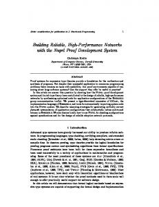
Chapter 1 Introduction In July 1958, Jack Kilby of Texas Instruments suggested building all of the components of a circuit completely in silicon [1]. By September 12, 1958, Kilby had built a working model of the first “solid circuit,” the size of a pencil point. A couple of months later in January 1959, Robert Noyce of Fairchild Semiconductor developed a better way to connect the different components of a circuit [2], [3]. Later, in the spring of 1959, Fairchild Semiconductor demonstrated the first planar circuit – a “unitary circuit.” The first monolithic integrated circuit (IC) was born, where multiple transistors coexisted with passive components on the same physical substrate [4]. Microphotographs of the first IC (Texas Instruments, 1958), the first monolithic IC (Fairchild Semiconductor, 1959), and the recent high performance dual core Montecito microprocessor (Intel Corporation, 2005) are depicted in Fig. 1.1. In 1960, Jean Hoerni invented the planar process [5]. Later, in 1960, Dawon Kahng and Martin Atalla
2
(a)
(b)
(c)
Figure 1.1: Microphotographs of the first integrated circuit (IC) and first monolithic IC along with a high performance, high complexity IC (the die size is not to scale). (a) The first IC (Texas Instruments, 1958), (b) the first monolithic IC (Fairchild Semiconductor, 1959), and (c) the high performance dual core Montecito microprocessor (Intel Corporation, 2005).
3
demonstrated the first silicon based MOSFET [6], followed in 1967 by the first silicon gate MOSFET [7]. These seminal inventions resulted in the explosive growth of today’s multi-billion dollar microelectronics industry. The fundamental cause of this growth in the microelectronics industry has been made possible by technology scaling, particularly in CMOS technology. With the on-going miniaturization of integrated circuit feature size, the design of the power and ground distribution networks has become a challenging task. These challenges arise from shorter transition times, lower noise margins, higher currents, and increased current densities. Furthermore, the power supply voltage has decreased in order to lower dynamic power dissipation. A greater number of transistors increases the total current drawn from the power delivery network. Simultaneously, the higher switching speed of these greater number of smaller transistors produces faster and larger current transients in the power distribution network [8]. The high average currents produce large ohmic IR voltage drops [9] and the fast current transients cause large inductive L
dI voltage drops [10] (∆I noise) in dt
the power distribution networks. The power distribution networks are designed to minimize these voltage drops, maintaining the power and ground supply voltages at the terminals of the current load within specified noise margins. If the power supply voltage drops too much, the performance and functionality of the circuit will
4
be severely compromised. Furthermore, excessive overshoot of the supply voltage can affect circuit reliability [11]. The goal of this chapter is to introduce the problem of power delivery in integrated circuits, discuss the deleterious effects of power distribution noise, and provide guidance and perspective to the rest of this dissertation. Fundamental issues in the design of the power and ground distribution networks in modern high performance, high complexity ICs are described in Section 1.1. The adverse effects of power supply noise on circuit operation are discussed in Section 1.2. Finally, the overall structure of the dissertation and a description of each chapter are outlined in Section 1.3.
1.1
The Problem of Power Delivery
The problem of power delivery is illustrated in Fig. 1.2, where a circuit model of a power distribution system is shown [12]. A power distribution system consists of a power supply, a current load, and interconnect lines connecting the supply to the load. The power supply is modeled as an ideal voltage source providing nominal power and ground voltage levels (Vdd and Vgnd ). The current load is modeled as a variable current source Iload (t), representing a transistor or circuit module. Note that the power and ground lines have a finite parasitic resistance R g and Rp and inductance Lg and Lp . As a result of the non-ideal interconnect lines connecting the supply and the load, resistive voltage drops ∆VR = IR and inductive voltage drops ∆VL = L
dI dt
5
develop across the parasitic interconnect impedances, as the load draws current from the power distribution system. The voltage levels at the load terminals, therefore, deviate from the nominal power supply levels, dropping to V dd − IRp − L power terminal and rising to Vgnd + IRg + L
dI at the dt
dI at the ground terminal, as shown in dt
Fig. 1.2.
V = Vdd Power + supply − V = Vgnd
Lp
Rp I (t) load
Iload (t)
Rg
Iload (t)
Lg
V = Vdd − IRp − Lp dI dt Power load V = Vgnd + IRg + Lg dI dt
Figure 1.2: Circuit model of a power delivery system. A power and ground distribution system consists of a power supply, current load, and non-ideal interconnect lines.
These fluctuations in the supply voltages are referred to as power supply noise [13]. Power supply noise adversely affects circuit operation through several mechanisms, as described in Section 1.2. The power distribution noise at the terminals of the load should be maintained within the maximum allowed voltage fluctuations (noise margins) to ensure correct operation of the overall system. The power distribution system should therefore be carefully designed, supplying sufficient current to each transistor while satisfying target noise margins.
6
To maintain the supply voltage within specified noise margins, the output impedance of the power distribution network should be low as seen from the power and ground terminals of the circuit. IC technologies are expected to scale for at least another decade [8]. As a result, the average and transient currents drawn from the power delivery network will continue to rise. Simultaneously, the power supply voltage will be scaled to manage on-chip power consumption. The target impedance of a power distribution network in high speed, high complexity ICs such as microprocessors will therefore continue to drop, reaching an inconceivable level of 250 µΩ by the year 2017 [8], as depicted in Fig. 1.3. Decoupling capacitors are often used to reduce the impedance of a power distribution system and provide the required charge to the switching circuits, lowering the power supply noise [14]. At high frequencies, however, only on-chip decoupling capacitors can be effective due to the high parasitic impedance of the power network connecting a decoupling capacitor to the current load [15]. On-chip decoupling capacitors, however, reduce the self-resonant frequency of a power distribution system, resulting in high amplitude power supply voltage fluctuations at the resonant frequencies. A system of on-chip decoupling capacitors should therefore be carefully designed to provide a low impedance, resonant-free power distribution network over the entire range of operating frequencies, while delivering sufficient charge to the switching circuits to maintain the local power supply voltages within target noise margins [11].
Target impedance, (mOhms)
7
0.8
Ztarget =
0.7
Vdd Ripple Iload
0.6 0.5 0.4 0.3 0.2 2005
2007
2009
2011
2013
2015
2017
Computer generation, year Figure 1.3: Projections of the target impedance of a power distribution system. The target impedance will continue to drop for future technology generations at an aggressive rate of 1.25 X per computer generation [8].
1.2
Detrimental Effects of Power Distribution Noise
Power distribution noise adversely affects the operation of an IC through several mechanisms. The propagation delay of the on-chip signals depends upon the power supply level during a signal transition. If the rail-to-rail power voltage is reduced as a result of power supply variations, the gate-to-source voltage of the NMOS and PMOS transistors decreases, lowering the output current of the transistors. The signal delay therefore increases as compared to the delay under a nominal power supply voltage. Conversely, a higher supply voltage will shorten the propagation delay. The power
8
noise thereby results in increased delay uncertainty of the clock signals and an increase in the maximum delay of the data paths [16], [17]. Power supply noise can therefore limit the maximum operating frequency of an integrated circuit [18], [19], [20]. Power supply noise can also result in on-chip clock jitter. A phase-locked loop (PLL) with a voltage controlled oscillator (VCO) is typically utilized to generate the on-chip clock signal in high performance microprocessors. PLLs and VCOs are highly susceptible to power supply variations, resulting in phase deviations in the on-chip clock signal, as illustrated in Fig. 1.4. These phase deviations are typically referred to as clock jitter [21], [22]. Cycle-to-cycle jitter (or random deviations) refers to independent deviations from the ideal phase at different edges of a clock signal. Peak-to-peak jitter (or systematic variations) refers to variations of the on-chip clock phase as compared to the system clock signal. Clock jitter contributes directly to the delay uncertainty of the clock signals and degrades the synchronization among the different clock domains, compromising overall system performance [23]. It is therefore important to provide a low noise power supply voltage to the on-chip clock generation and distribution circuitry to ensure fault-free operation of the overall system [24]. In digital ICs with single-ended signaling, the power and ground supply networks serve as a reference voltage for the on-chip data signals. Variations in the supply voltage therefore create a discrepancy between the power and ground voltage levels at the interface between the transmitting and receiving circuits. Power noise induced
9
uncertainty in these reference voltages degrades the noise margins of the on-chip signals, jeopardizing the functionality of a system.
PLL output (clock)
tdelay
Power supply level Vdd Vdd − IRp − LpdI/dt
Figure 1.4: A phase error (or jitter) in the on-chip clock signal due to power supply noise. The original clock signal is depicted by a solid line and the delayed clock signal is shown by a dashed line.
In contemporary CMOS technologies, the thickness of the gate silicon dioxide has been dramatically reduced to several molecular layers to increase the current drive of the transistors. The maximum power supply voltage is limited by the maximum electric field within the gate oxide layer [25]. Variations in the power supply can increase the voltage across the gate oxide layer above the nominal power supply, degrading the long term reliability of the transistors [26]. Overshoots of the power supply voltage should therefore be limited to avoid significant degradation in reliability.
10
1.3
Dissertation Outline
Methodologies for designing power distribution grids in high performance nanoscale ICs is the primary topic of this dissertation. The related topic of placing on-chip decoupling capacitors to mitigate power distribution noise in nanometer ICs is also discussed. Design techniques and expressions to determine the location and magnitude of the on-chip decoupling capacitors are developed. Several power distribution schemes with multiple supply voltages are presented, resulting in reduced power distribution noise. Decoupling capacitance is introduced in Chapter 2. A historical perspective of capacitance is provided. The decoupling capacitor is shown to be analogous to a reservoir of charge. A hydraulic analogy of a hierarchical placement of decoupling capacitors is introduced. It is demonstrated that the impedance of a power distribution system can be maintained below target specifications over an entire range of operating frequencies by utilizing a hierarchy of decoupling capacitors. Antiresonance in the impedance of a power distribution system with decoupling capacitors is also intuitively explained in this chapter. Different types of on-chip decoupling capacitors are compared. Several allocation strategies for placing on-chip decoupling capacitors are reviewed. Systems with multiple power supply voltages are described in Chapter 3. Several multi-voltage structures are reviewed. Primary challenges in integrated circuits with
11
multiple power supplies are discussed. The power savings is shown to depend upon the number and magnitude of the available power supply voltages. Rules of thumb are presented to determine the optimum number and magnitude of the multiple power supplies, maximizing any savings in power. On-chip power distribution grids with multiple power supply voltages are discussed in Chapter 4. A power distribution grid with multiple power supplies and multiple grounds is presented. It is shown that this power distribution grid structure results in reduced voltage fluctuations as seen at the terminals of the current load, as compared to traditional power distribution grids with multiple supply voltages and a single ground. It is noted that a multi-power and multi-ground power distribution grid can be an alternative to a single supply voltage and single ground power distribution system. On-chip power noise reduction techniques in high performance ICs are the primary subject of Chapter 5. A design technique to lower ground bounce in noise sensitive circuits is described. An on-chip noise-free ground is added to divert ground noise from the sensitive nodes. An on-chip decoupling capacitor tuned in resonance with the parasitic inductance of the interconnects is shown to provide an additional low impedance ground path, reducing the power noise. The dependence of ground noise reduction mechanisms on various system parameters is also discussed.
12
Decoupling capacitors for power distribution systems with multiple power supply voltages is the topic of the following chapter – Chapter 6. With the introduction of a second power supply, the noise at one power supply can propagate to the other power supply, producing power and signal integrity problems in the overall system. The interaction between the two power distribution networks should therefore be considered. The dependence of the impedance and magnitude of the voltage transfer function on the parameters of the power distribution system is investigated. Design techniques to cancel and shift the antiresonant spikes out of the range of the operational frequencies are also presented. On-chip decoupling capacitors have traditionally been allocated into the available white space on a die. The efficacy of the on-chip decoupling capacitors depends upon the impedance of the power/ground lines connecting the capacitors to the current loads and power supplies. A design methodology for placing on-chip decoupling capacitors is presented in Chapter 7. The maximum effective radii of an on-chip decoupling capacitor as determined by the target impedance (during discharge) and the charge time are developed. Two criteria to estimate the minimum required on-chip decoupling capacitance are also presented. As the minimum feature size continues to scale, additional on-chip decoupling capacitance will be required to support increasing current demands. A larger on-chip decoupling capacitance requires a greater area which cannot conveniently be placed
13
in the proximity of the switching circuits. Moreover, a large decoupling capacitor exhibits a distributed behavior. A lumped model of an on-chip decoupling capacitor, therefore, results in underestimating the capacitance requirements, thereby increasing the power noise. A methodology for efficiently placing on-chip distributed decoupling capacitors is the subject of Chapter 8. Design techniques to estimate the location and magnitude of a system of distributed decoupling capacitors are presented. Various tradeoffs in the design of a system of distributed on-chip decoupling capacitors are also investigated. In Chapter 9, the research described in the dissertation is summarized. Directions for future research are suggested in Chapter 10. A multi-layer model of an on-chip power distribution grid needs to be developed to accurately analyze power noise and signal integrity in high complexity ICs. Chip-package co-design methodologies will be developed to accurately analyze power and signal integrity in nanoscale ICs. On-chip decoupling capacitors in mixed-signal and RF ICs can dramatically worsen substrate noise coupling. A design methodology for placing on-chip decoupling capacitors in mixed-signal ICs and systems-on-chip will be required. Techniques for placing on-chip decoupling capacitors in 3-D ICs, significantly reducing the overall on-chip decoupling capacitance, are also proposed as future research.
14
Chapter 2 Decoupling Capacitance The on-going miniaturization of integrated circuit feature sizes has placed significant requirements on the on-chip power and ground distribution networks. Circuit integration densities rise with each very deep submicrometer (VDSM) technology generation due to smaller devices and larger dies. The on-chip current densities and the total current also increase. Simultaneously, the higher switching speed of smaller transistors produces faster current transients in the power distribution network. Supplying high average currents and continuously increasing transient currents through the high impedance on-chip interconnects results in significant fluctuations of the power supply voltage in scaled CMOS technologies. Such a change in the supply voltage is referred to as power supply noise. Power supply noise adversely affects circuit operation through several mechanisms, as described in Chapter 1. Supplying sufficient power current to high performance ICs has
15
therefore become a challenging task. Large average currents result in increased IR noise and fast current transients result in increased L
dI voltage drops (∆I noise) [27]. dt
Decoupling capacitors are often utilized to manage this power supply noise. Decoupling capacitors have a significant effect on the principal characteristics of an integrated circuit, i.e., speed, cost, and power. Due to the importance of decoupling capacitors in current and future ICs, significant research has been described over the past several decades, covering different areas such as hierarchical placement of decoupling capacitors, sizing and placing of on-chip decoupling capacitors, resonant phenomenon in power distribution systems with decoupling capacitors, and static on-chip power dissipation due to leakage current through the gate oxide. In this chapter, a brief review of the background of decoupling capacitance is provided. In Section 2.1, the concept of a decoupling capacitance is introduced and an historical retrospective is described. A practical model of a decoupling capacitor is also introduced. In Section 2.2, the impedance of a power distribution system with decoupling capacitors is presented. Target specifications of the impedance of a power distribution system are reviewed. Antiresonance phenomenon in a system with decoupling capacitors is intuitively explained. A hydraulic analogy of the hierarchical placement of decoupling capacitors is also presented. Intrinsic and intentional on-chip decoupling capacitances are discussed and compared in Section 2.3. Different types of on-chip decoupling capacitors are qualitatively analyzed in Section 2.4.
16
The advantages and disadvantages of several types of widely used on-chip decoupling capacitors are also discussed in Section 2.4. Three strategies for allocating on-chip decoupling capacitors are described in Section 2.5. Finally, some conclusions are offered in Section 2.6.
2.1
Introduction to Decoupling Capacitance
Decoupling capacitors are often used to maintain the power supply voltage within specification so as to provide signal integrity while reducing electromagnetic interference (EMI) radiated noise. In this dissertation, the use of decoupling capacitors to mitigate power supply noise is investigated. The concept of a decoupling capacitor is introduced in this section. A historical retrospective is presented in Section 2.1.1. A description of a decoupling capacitor as a reservoir of charge is discussed in Section 2.1.2. Decoupling capacitors are shown to be an effective way to provide the required charge to a switching current load within a short period of time. A practical model of a decoupling capacitor is presented in Section 2.1.3.
2.1.1
Historical Retrospective
About 600 BC, Thales of Miletus recorded that the ancient Greeks could generate sparks by rubbing balls of amber on spindles [28]. This is the triboelectric effect [29],
17
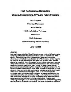
the mechanical separation of charge in a dielectric (insulator). This effect is the basis of the capacitor. In October 1745, Ewald Georg von Kleist of Pomerania invented the first recorded capacitor: a glass jar coated inside and out with metal. The inner coating was connected to a rod that passed through the lid and ended in a metal sphere, as shown in Fig. 2.1 [30]. By layering the insulator between two metal plates, von Kleist dramatically increased the charge density. Before Kleist’s discovery became widely known, a Dutch physicist Pieter van Musschenbroek independently invented a very similar capacitor in January 1746 [31]. It was named the Leyden jar, after the University of Leyden where van Musschenbroek worked. Benjamin Franklin investigated the Leyden jar and proved that the charge was stored on the glass, not in the water as others had assumed [32]. Originally, the units of capacitance were in “jars.” A jar is equivalent to about 1 nF. Early capacitors were also known as condensors, a term that is still occasionally used today. The term condensor was coined by Alessandro Volta in 1782 (derived from the Italian condensatore), with reference to the ability of a device to store a higher density of electric charge than a normal isolated conductor [32].
18
Positive terminal
Metal rod
�������� ����������� ������� ������� ���������������������� �������� ��������� ���������������������� ������� ������������� Tin foil
Wire Negative terminal
Figure 2.1: Leyden jar originally developed by Ewald Georg von Kleist in 1745 and independently invented by Pieter van Musschenbroek in 1746. The charge is stored on the glass between two tin foils (capacitor plates) [30].
2.1.2
Decoupling Capacitor as a Reservoir of Charge
A capacitor consists of two electrodes, or plates, each of which stores an equal amount of opposite charge. These two plates are conductive and are separated by an insulator (dielectric). The charge is stored on the surface of the plates at the boundary with the dielectric. Since each plate stores an equal but opposite charge, the net charge across the capacitor is always zero.
19
The capacitance C of a capacitor is a measure of the amount of charge Q stored on each plate for a given potential difference (voltage V ) which appears between the plates, C=
Q . V
(2.1)
The capacitance is proportional to the surface area of the conducting plate and inversely proportional to the distance between the plates [33]. The capacitance is also proportional to the permittivity of the dielectric substance that separates the plates. The capacitance of a parallel-plate capacitor is
C≈
²A , d
(2.2)
where ² is the permittivity of the dielectric, A is the area of the plates, and d is the spacing between the plates. Equation (2.2) is only accurate for a plate area much greater than the spacing between the plates, A À d2 . In general, the capacitance of the metal interconnects placed over the substrate is composed of three primary components: a parallel plate capacitance, fringe capacitance, and lateral flux (side) capacitance [34], as shown in Fig. 2.2. Accurate closed-form expressions have been developed by numerically fitting a model that describes parallel lines above the plane or between two parallel planes [35], [36], [37], [38], [39], [40].
20
Cl
Metal Cf
Cf
Cp
Cp
Metal Cp
Cp
Cf
Cf
Substrate
Figure 2.2: Capacitance of two metal lines placed over a substrate. Three primary components compose the total capacitance of the on-chip metal interconnects. C l denotes the lateral flux (side) capacitance, Cf denotes the fringe capacitance, and Cp denotes the parallel plate capacitance.
As opposite charges accumulate on the plates of a capacitor across an insulator, a voltage develops across the capacitor due to the electric field formed by the opposite charges. Work must be done against this electric field as more charge is accumulated. The energy stored in a capacitor is equal to the amount of work required to establish the voltage across the capacitor. The energy stored in the capacitor is
1 Q2 1 1 = V Q. Estored = CV 2 = 2 2 C 2
(2.3)
From a physical perspective, a decoupling capacitor serves as an intermediate storage of charge and energy. The decoupling capacitor is located between the power supply and current load, i.e., electrically closer to the switching circuit. The decoupling capacitor is therefore more efficient in terms of supplying charge as compared to a remote power supply. The amount of charge stored on the decoupling capacitor
21
is limited by the voltage and the capacitance. Unlike a decoupling capacitor, the power supply can provide an almost infinite amount of charge. A hydraulic model of a decoupling capacitor is illustrated in Fig. 2.3. Similar to water stored in a water tank and connected to the consumer through a system of pipes, the charge on the decoupling capacitor stored between the conductive plates is connected to the current load through a hierarchical interconnect system. To be effective, the decoupling capacitor should satisfy two requirements. First, the capacitor should have sufficient capacity to store a significant amount of energy. Second, to supply sufficient power at high frequencies, the capacitor should be able to release and accumulate energy at a high rate.
2.1.3
Practical Model of a Decoupling Capacitor
Decoupling capacitors are often used in power distribution systems to provide the required charge in a timely manner and to reduce the output impedance of the overall power delivery network [41]. An ideal decoupling capacitor is effective over the entire frequency range: from DC to the maximum operating frequency of a system. Practically, a decoupling capacitor is only effective over a certain frequency range. The impedance of a practical decoupling capacitor decreases linearly with frequency at low frequencies (with a slope of -20 dB/dec in a logarithmic scale). As the frequency increases, the impedance of the decoupling capacitor increases linearly with frequency
22
Water tank
Capacitor
Water Charge
Pipe Interconnect
To consumer
To current load
Figure 2.3: Hydraulic model of a decoupling capacitor as a reservoir of charge. Similar to water stored in a water tank and connected to the consumer through a system of pipes, charge at the decoupling capacitor is stored between the conductive plates connected to the current load through a hierarchical interconnect system.
(with a slope of 20 dB/dec in a logarithmic scale), as shown in Fig. 2.4. This increase in the impedance of a practical decoupling capacitor is due to the parasitic inductance of the decoupling capacitor. The parasitic inductance is referred to as the effective series inductance (ESL) of a decoupling capacitor [42]. The impedance of a decoupling capacitor reaches the minimum impedance at the frequency ω = √
1 . This LC
frequency is known as the resonant frequency of a decoupling capacitor. Observe that the absolute minimum impedance of a decoupling capacitor is limited by the parasitic resistance, i.e., the effective series resistance (ESR) of a decoupling capacitor. The
23
parasitic resistance of a decoupling capacitor is due to the resistance of the metal leads and conductive plates and the dielectric losses of the insulator. The ESR and ESL of an example on-chip metal-oxide-semiconductor (MOS) decoupling capacitor are illustrated in Fig. 2.5. Note that the parasitic inductance of the decoupling capacitor is determined by the area of the current loops, decreasing with smaller area, as shown in Fig. 2.5(b) [43].
Ideal
Practical
ESR
ca
0
pa
dB
cit
/d
ec
iv
e
Frequency (log)
−2
0
ca
pa
ec
/d
dB
/d
cit
ESL
C
iv
e
20
ec
dB
e
tiv
c du
in
ESR
−2
Impedance (log)
Impedance (log)
C
ω res
Frequency (log)
Figure 2.4: Practical model of a decoupling capacitor. The impedance of a practical decoupling capacitor decreases linearly with frequency, reaching the minimum at a resonant frequency. Beyond the resonant frequency, the impedance of the decoupling capacitor increases linearly with frequency due to the ESL. The minimum impedance is determined by the ESR of the decoupling capacitor.
24
Drain/Source
Gate
n+
� �� � �� � �� � �� � �� � �� � �� � �� � C�� � ox�� � �� �� � ���� � � ��� ���� � � ��� ���� � � ��� ���� � � ��� ���� � � ��� ���� � � ��� ���� � � ��� ���� � � ��� ���� � � ��� ���� � � ��� ���� � � �� � �� � �� � �� � �� � �� � �� � �� � �� � �� � �� ��� � � � �� � �� � �� � �� � �� � �� � �� � �� � �� � �� ��� � � � �� � �� � �� � �� � �� � �� � �� � �� � �� � �� ����� ESR
Cd
Cd
n+ ESR
n− well p+ substrate
(a) ESR of a MOS-based decoupling capacitor. The ESR of an on-chip MOS decoupling capacitor is determined by the doping profiles of the n+ regions and n− well, the size of the capacitor, and the impedance of the vias and gate material [44].
Power/Ground line
�
�
�
�
�
�
�
�
�
�
�
�
�
�
�
�
�
�
�
�
�
�
�
�
�
�
�
�
�
�
�
�
�
�
�
�
�
�
�
�
�
�
�
�
�
�
�
�
�
�
�
�
�
�
�
�
�
�
�
�
�
�
�
�
�
�
�
�
�
�
�
�
�
�
�
�
�
�
�
�
�
�
�
�
�
�
�
�
� �� �
�
�
�
�
�
�
�
�
�
�
�
�
�
�
�
�
�
�
�
�
�
�
�
�
�
�
�
�
�
�
�
�
�
�
�
�
�
�
�
�
�
�
�
Vias
Cox
� � � � � � � � � � � � � � � � � � � � � � n+
n+
n− well p+ substrate
(b) ESL of a MOS-based decoupling capacitor. The ESL of an on-chip MOS decoupling capacitor is determined by the area of the current return loops. The parasitic inductance is lowered by shrinking the area of the current return loops.
Figure 2.5: Physical structure of an on-chip MOS decoupling capacitor.
25
The impedance of a decoupling capacitor depends upon a number of characteristics. For instance, as the capacitance is increased, the capacitive curve moves down and to the right (see Fig. 2.4). Since the parasitic inductance for a particular capacitor is fixed, the inductive curve remains unaffected. As different capacitors are selected, the capacitive curve moves up and down relative to the fixed inductive curve. The primary way to decrease the total impedance of a decoupling capacitor for a specific semiconductor package is to increase the value of the capacitor [45]. Note that to move the inductive curve down, lowering the total impedance characteristics, a number of decoupling capacitors should be connected in parallel. In the case of identical capacitors, the total impedance is reduced by a factor of two for each doubling in the number of capacitors [46].
2.2
Impedance of Power Distribution System with Decoupling Capacitors
As described in Section 2.1.2, a decoupling capacitor serves as a reservoir of charge, providing the required charge to the switching current load. Decoupling capacitors are also used to lower the impedance of the power distribution system. The impedance of a decoupling capacitor decreases rapidly with frequency, shunting the high frequency currents and reducing the effective current loop of a power distribution network. The
26
impedance of the overall power distribution system with decoupling capacitors is the subject of this section. In Section 2.2.1, the target impedance of a power distribution system is introduced. It is shown that the impedance of a power distribution system should be maintained below a target level to guarantee fault-free operation of the entire system. Antiresonance phenomenon is presented in Section 2.2.2. A hydraulic analogy of a system of decoupling capacitors is described in Section 2.2.3. The analogy is drawn between a water supply system and the hierarchical placement of decoupling capacitors at different levels of a power delivery network.
2.2.1
Target Impedance of a Power Distribution System
To ensure a small variation in the power supply voltage under a significant current load, the power distribution system should exhibit a small impedance as seen from the current load within the frequency range of interest [47]. A circuit network representing the impedance of a power distribution system as seen from the terminals of the current load is shown in Fig. 2.6. The impedance of a power distribution system is with respect to the terminals of the load circuits. In order to ensure correct and reliable operation of an IC, the impedance of a power distribution system should be maintained below a certain upper bound Ztarget in the frequency range from DC to the maximum operating frequency f0 of the system [48], [49], [50]. The maximum tolerable impedance of a power
27
���$
�&�$
� ��
� %$
�&%$
� ��
� %�
� %�
� ��
��� "
�&�"
�#�" � " ���"
�!�� � � � ��
� �� � � ����
� ���
� ��
� �%
� �%
��������� ��%"
�&%"
Figure 2.6: A circuit network representing the impedance of a power distribution system with decoupling capacitors as seen from the terminals of the current load. The ESR and ESL of the decoupling capacitors are also included. Subscript p denotes the power paths and subscript g denotes the ground path. Superscripts r, b, p, and c refer to the voltage regulator, board, package, and on-chip power delivery networks, respectively.
distribution system is henceforth referred to as the target impedance. Note that the maximum operating frequency f0 is determined by the switching time of the on-chip signal transients, rather than by the clock frequency. The shortest signal switching time is typically an order of magnitude smaller than the clock period. The maximum operating frequency is therefore considerably higher than the clock frequency. One primary design objective of an effective power distribution system is to ensure that the output impedance of the network is below a target output impedance level. It is therefore important to understand how the output impedance of the circuit, shown schematically in Fig. 2.6, depends upon the impedance of the comprising circuit elements. A power distribution system with no decoupling capacitors is shown in Fig. 2.7. The power source and load are connected by interconnect with resistive and
28
inductive parasitic impedances. The magnitude of the impedance of this network is
|Ztot (ω)| = |Rtot + jωLtot | ,
(2.4)
where Rtot and Ltot are the total resistance and inductance of the power distribution system, respectively,
p g Rtot = Rtot + Rtot ,
(2.5)
p Rtot = Rpr + Rpb + Rpp + Rpc ,
(2.6)
g Rtot = Rgr + Rgb + Rgp + Rgc ,
(2.7)
Ltot = Lptot + Lgtot ,
(2.8)
Lptot = Lrp + Lbp + Lpp + Lcp ,
(2.9)
Lgtot = Lrg + Lbg + Lpg + Lcg .
(2.10)
')*(
+ *(
')*,
+ *,
' **
+ **
'.* -
+ *-
'/0(
+ 0(
' 0,
+ 0,
' *0
+ *0
'.0-
+ 0-
Figure 2.7: A circuit network representing the impedance of a power distribution system without decoupling capacitors.
29
The variation of the impedance with frequency is illustrated in Fig. 2.8. To satisfy a specification at low frequency, the resistance of the power delivery network should be sufficiently low, Rtot < Ztarget . Above the frequency fLtot =
1 Rtot , however, the 2π Ltot
impedance of the power delivery network is dominated by the inductive reactance jωLtot and increases linearly with frequency, exceeding the target impedance at the
Impedance, log Z
frequency fmax =
1 Ztarget . 2π Ltot
Z target Rtot
fL
tot
f0
fmax
Frequency, log f
Figure 2.8: Impedance of a power distribution system without decoupling capacitors. The shaded area denotes the target impedance specifications of the overall power distribution system.
The high frequency impedance should be reduced to satisfy the target specifications. Opportunities for reducing the inductance of the power and ground paths of a power delivery network are limited [51], [52], [53], [54], [55]. The inductance of the power distribution system is mainly determined by the board and package
30
interconnects [56], [57], [58]. The feature size of the board and package level interconnect depends upon the manufacturing technology. The output impedance of a power distribution system is therefore highly inductive which is difficult to lower [59]. The high frequency impedance is effectively reduced by placing capacitors across the power and ground interconnections. These shunting capacitors effectively terminate the high frequency current loop, permitting the current to bypass the inductive interconnect, such as the board and package power delivery networks [60], [61], [62], [63]. The high frequency impedance of the system as seen from the current load terminals is thereby reduced. Alternatively, at high frequencies, the capacitors decouple the high impedance paths of the power delivery network from the load. These capacitors are therefore referred to as decoupling capacitors [64], [65]. Several stages of decoupling capacitors are typically utilized to maintain the output impedance of a power distribution system below a target impedance [46], [66], as described in Section 2.2.3.
2.2.2
Antiresonance
Decoupling capacitors are a powerful technique to reduce the impedance of a power distribution system over a significant range of frequencies. A decoupling capacitor, however, reduces the resonant frequency of a power delivery network, making the system susceptible to resonances. Unlike the classic self-resonance in a series circuit
31
formed by a decoupling capacitor combined with a parasitic resistance and inductance [67], [68] or by an on-chip decoupling capacitor and the parasitic inductance of the package (i.e., chip-package resonance) [69], [70], antiresonance occurs in a circuit formed by two capacitors connected in parallel. At the resonant frequency, the impedance of the series circuit decreases in the vicinity of the resonant frequency, reaching the absolute minimum at the resonant frequency determined by the ESR of the decoupling capacitor. At antiresonance, however, the circuit impedance drastically increases, producing a distinctive peak, as illustrated in Fig. 2.9. This antiresonant peak can result in system failures as the impedance of the power distribution system becomes greater than the maximum tolerable impedance Z target . The antiresonance phenomenon in a system with parallel decoupling capacitors is the subject of this section. To achieve a low impedance power distribution system, multiple decoupling capacitors are placed in parallel. The effective impedance of a power distribution system with several identical capacitors placed in parallel is illustrated in Fig. 2.10. Observe that the impedance of the power delivery network is reduced by a factor of two as the number of capacitors is doubled. Also note that the effective drop in the impedance of a power distribution system diminishes rapidly with each additional decoupling capacitor. It is therefore desirable to utilize decoupling capacitors with a sufficiently low ESR in order to minimize the number of capacitors required to satisfy a target
32
2.5
Antiresonant spike
Impedance, Ohms (log scale)
2 1.5
Ztarget
1 0.5 0 −0.5 −1 −1.5 −2 6.6
6.8
7
7.2
7.4
7.6
7.8
8
Frequency, Hz (log scale)
Figure 2.9: Antiresonance of the output impedance of a power distribution network. Antiresonance results in a distinctive peak, exceeding the target impedance specification.
impedance specification [46]. A number of decoupling capacitors with different magnitudes is typically used to maintain the impedance of a power delivery system below a target specification over a wide frequency range. Capacitors with different magnitudes connected in parallel, however, result in a sharp antiresonant peak in the system impedance [15]. The antiresonance phenomenon for different capacitive values is illustrated in Fig. 2.11. The antiresonance of parallel decoupling capacitors can be explained as follows. In the frequency range from f1 to f2 , the impedance of the capacitor C1 has become inductive whereas the impedance of the capacitor C2 remains capacitive (see Fig. 2.11). Thus,
33
an LC tank is formed in the frequency range from f1 to f2 , producing a peak at the resonant frequency located between f1 and f2 . As a result, the total impedance drastically increases and becomes greater than the target impedance, causing a system to fail. 1
10
Impedance, Ohms
0
10
−1
10
−2
n=1 n=2 n=4 n=8 n=16
10
−3
10
7
10
8
9
10
10
10
10
Frequency, Hz
Figure 2.10: Impedance of a power distribution system with n identical decoupling capacitors connected in parallel. The ESR of each decoupling capacitor is R = 0.1 Ω, the ESL is L = 100 pH, and the capacitance is C = 1 nF. The impedance of a power distribution system is reduced by a factor of two as the number of capacitors is doubled.
The magnitude of the antiresonant spike can be effectively reduced by lowering the parasitic inductance of the decoupling capacitors. For instance, as discussed in [46], the magnitude of the antiresonant spike is significantly reduced if board decoupling
34
capacitors are mounted on low inductance pads. The magnitude of the antiresonant spike is also determined by the ESR of the decoupling capacitor, decreasing with larger parasitic resistance. Large antiresonant spikes are produced when low ESR decoupling capacitors are placed on inductive pads. A high inductance and low resistance result in a parallel LC circuit with a high quality factor Q,
Q=
L . R
(2.11)
In this case, the magnitude of the antiresonant spike is amplified by Q. Decoupling capacitors with a low ESR should therefore always be used on low inductance pads (with a low ESL). Antiresonance also becomes well pronounced if a large variation exists between the capacitance values. This phenomenon is illustrated in Fig. 2.12. In the case of two capacitors with distinctive nominal values (C1 À C2 ), a significant gap between two capacitances results in a sharp antiresonant spike with a large magnitude in the frequency range from f1 to f2 , violating the target specification Ztarget , as shown in Fig. 2.12(a). If another capacitor with nominal value C 1 > C3 > C2 is added, the antiresonant spike is canceled by C3 in the frequency range from f1 to f2 . As a result, the overall impedance of a power distribution system is maintained below the target specification over a broader frequency range, as shown in Fig. 2.12(b). As described in [71], the high frequency impedance of two parallel decoupling capacitors
35
Antiresonant spike C2
e tiv
c it
uc
pa ive
Impedance, log Z
Ca f1
Ind
C1
f2
Frequency, log f Figure 2.11: Antiresonance of parallel capacitors, C1 > C2 , L1 = L2 , and R1 = R2 . A parallel LC tank is formed in the frequency range from f1 to f2 . The total impedance drastically increases in the frequency range from f1 to f2 (the solid line), producing an antiresonant spike.
is only reduced by a factor of two (or 6 dB) as compared to a single capacitor. It is also shown that adding a smaller capacitor in parallel with a large capacitor results in only a small reduction in the high frequency impedance. Antiresonances are effectively managed by utilizing decoupling capacitors with a low ESL and by placing a greater number of decoupling capacitors with progressively decreasing magnitude, shifting the antiresonant spike to the higher frequencies (out of the range of the operating frequencies of the circuit) [72].
36
Impedance, log Z
C2
C1
Z target
1 fres
2 fres
f0
Frequency, log f (a) Impedance of a power distribution system with two decoupling capacitors, C1 À C2
Impedance, log Z
C2 C3 C1
Z target
1 fres
3 fres
2 fres
f0
Frequency, log f (b) Impedance of a power distribution system with three decoupling capacitors, C1 > C3 > C2
Figure 2.12: Antiresonance of parallel capacitors. (a) A large gap between two capacitances results in a sharp antiresonant spike with a large magnitude in the frequency range from f1 to f2 , violating the target specification Ztarget . (b) If another capacitor with magnitude C1 > C3 > C2 is added, the antiresonant spike is canceled by C3 in the frequency range from f1 to f2 . As a result, the overall impedance of the power distribution system is maintained below the target specification over the desired frequency range.
37
2.2.3
Hydraulic Analogy of Hierarchical Placement of Decoupling Capacitors
As discussed in Section 2.1.2, an ideal decoupling capacitor should provide a high capacity and be able to release and accumulate energy at a sufficiently high rate. Constructing a device with both high energy capacity and high power capability is, however, challenging. It is expensive to satisfy both of these requirements in an ideal decoupling capacitor. Moreover, these requirements are typically contradictory in most practical applications. The physical realization of a large decoupling capacitance requires the use of discrete capacitors with a large nominal capacity and, consequently, a large form factor. The large physical dimensions of the capacitors have two implications. The parasitic series inductance of a physically large capacitor is relatively high due to the increased area of the current loop within the capacitors. Furthermore, due to technology limitations, the large physical size of the capacitors prevents placing the capacitors sufficiently close to the current load. A greater physical separation increases the inductance of the current path from the capacitors to the load. A tradeoff therefore exists between the high capacity and low parasitic inductance of a decoupling capacitor for an available component technology. Gate switching times of a few tens of picoseconds are common in modern high performance ICs, creating high transient currents in the power distribution system. At high frequencies, only those on-chip decoupling capacitors with a low ESR and a
38
low ESL can effectively maintain a low impedance power distribution system. Placing a sufficiently large on-chip decoupling capacitor requires a die area many times greater than the area of a typical circuit. Thus, while technically feasible, a single-tier decoupling solution is prohibitively expensive. A large on-chip decoupling capacitor is therefore typically built as a series of small decoupling capacitors connected in parallel. At high frequencies, a large on-chip decoupling capacitor exhibits a distributed behavior. Only on-chip decoupling capacitors located in the vicinity of the switching circuit can effectively provide the required charge to the current load within the proper time. An efficient approach to this problem is to hierarchically place multiple stages of decoupling capacitors, progressively smaller and closer to the load. Utilizing hierarchically placed decoupling capacitors produces a low impedance, high frequency power distribution system realized in a cost effective way. The capacitors are placed in several stages: on the board, package, and circuit die. Arranging the decoupling capacitors in several stages eliminates the need to satisfy both the high capacitance and low inductance requirements in the same decoupling stage [11]. The hydraulic analogy of the hierarchical placement of decoupling capacitors is shown in Fig. 2.13. Each decoupling capacitor is represented by a water tank. All of the water tanks are connected to the main water pipe connected to the consumer (current load). Water tanks at different stages are connected to the main pipe through the local water pipes, modeling different interconnect levels. The goal of the water
39
supply system (power delivery network) is to provide an uninterrupted water flow to the consumer at the required rate (switching time). The amount of water released by each water tank is proportional to the tank size. The rate at which the water tank is capable of providing water is inversely proportional to the size of the water tank and directly proportional to the distance from the consumer to the water tank. Power supply Voltage regulator bulk capacitor
Board capacitor
Package capacitor
On−chip capacitor
Consumer
Slowest
Response time decreases
Fastest
Figure 2.13: Hydraulic analogy of the hierarchical placement of decoupling capacitors. The decoupling capacitors are represented by the water tanks. The response time is proportional to the size of the capacitor and inversely proportional to the distance from a capacitor to the consumer. The on-chip decoupling capacitor has the shortest response time (located closer to the consumer), but is capable of providing the smallest amount of charge.
A power supply is typically treated as an infinite amount of charge. Due to large dimensions, the power supply cannot be placed close to the current load (the consumer). The power supply therefore has a long response time. Unlike the power
40
supply, an on-chip decoupling capacitor can be placed sufficiently closer to the consumer. The response time of an on-chip decoupling capacitor is significantly shorter as compared to the power supply. An on-chip decoupling capacitor is therefore able to respond to the consumer demand in a much shorter period of time but is capable of providing only a small amount of water (or charge). Allocating decoupling capacitors with progressively decreasing magnitudes and closer to the current load, an uninterrupted flow of charge can be provided to the consumer. In the initial moment, charge is only supplied to the consumer by the on-chip decoupling capacitor. As the on-chip decoupling capacitor is depleted, the package decoupling capacitor is engaged. This process continues until the power supply is activated. Finally, the power supply is turned on and provides the necessary charge with relatively relaxed timing constraints. The voltage regulator, board, package, and on-chip decoupling capacitors therefore serve as intermediate reservoirs of charge, relaxing the timing constraints for the power delivery supply. A hierarchy of decoupling capacitors is utilized in high performance power distribution systems in order to extend the frequency region of the low impedance characteristics to the maximum operating frequency f0 . The impedance characteristics of a power distribution system with board, package, and on-chip decoupling capacitors (see Fig. 2.6) are illustrated in Fig. 2.14. By utilizing the hierarchical placement of
41
decoupling capacitors, the antiresonant spike is shifted outside the range of operating frequencies (beyond f0 ). The overall impedance of a power distribution system is also maintained below the target impedance over the entire frequency range of interest (from DC to f0 ).
Impedance, log Z
Cc Cp Cb
Z target Rtot
f0
Frequency, log f Figure 2.14: Impedance of a power distribution system with board, package, and onchip decoupling capacitances. The overall impedance is shown with a black line. The impedance of a power distribution system with three levels of decoupling capacitors is maintained below the target impedance (dashed line) over the frequency range of interest. The impedance characteristics of the decoupling capacitors are shown by the thin solid lines.
Fully Compensated System A special case in the impedance of an RLC circuit formed by the decoupling capacitor and the parasitic inductance of the power/ground (P/G) lines is achieved
42
when the zeros of the tank circuit impedance cancel the poles, making the impedance purely resistive and independent of frequency,
RL = R C = R 0 =
L = RC C, RL
r
L , C
(2.12)
(2.13)
where RL and RC are the parasitic resistance of the P/G lines and the ESR of the decoupling capacitor, respectively. In this case, the impedance of the RLC tank is fully compensated. Equations (2.12) and (2.13) are equivalent to two conditions, i.e., the impedance at the lower frequencies is matched to the impedance at the high frequencies and the time constants of the inductor and capacitor currents are also matched. A constant, purely resistive impedance, characterizing a power distribution system with decoupling capacitors, is achieved across the entire frequency range of interest, if each decoupling stage is fully compensated [73], [74]. The resistance and capacitance of the decoupling capacitors in a fully compensated system are completely determined by the impedance characteristics of the power and ground interconnect and the location of the decoupling capacitors. The hierarchical placement of decoupling capacitors exploits the tradeoff between the capacity and the parasitic inductance of a capacitor to achieve an economically effective solution. The total decoupling capacitance of a hierarchical scheme
43
Ctotal = C b + C p + C c is larger than the total decoupling capacitance of a single-tier solution, where C b , C p , and C c are the board, package, and on-chip decoupling capacitances, respectively. The primary advantage of utilizing a hierarchical placement is that the inductive limit is imposed only on the final stage of decoupling capacitors which constitutes a small fraction of the total required decoupling capacitance. The constraints on the physical dimensions and parasitic impedance of the capacitors in the remaining stages are therefore significantly reduced. As a result, cost efficient electrolytic and ceramic capacitors can be used to provide medium size and high capacity decoupling capacitors [11].
2.3
Intrinsic vs Intentional On-Chip Decoupling Capacitance
Several types of on-chip capacitances contribute to the overall on-chip decoupling capacitance. The intrinsic decoupling capacitance is the inherent capacitance of the transistors and interconnects that exists between the power and ground terminals. The thin gate oxide capacitors placed on-chip to solely provide power decoupling are henceforth referred to as an intentional decoupling capacitance. The intrinsic decoupling capacitance is described in Section 2.3.1. The intentional decoupling capacitance is reviewed in Section 2.3.2.
44
2.3.1
Intrinsic Decoupling Capacitance
An intrinsic decoupling capacitance (or symbiotic capacitance) is the parasitic capacitance between the power and ground terminals within an on-chip circuit structure. The intrinsic capacitance is comprised of three types of parasitic capacitances [75]. One component of the intrinsic capacitance is the parasitic capacitance of the interconnect lines. Three types of intrinsic interconnect capacitances are illustrated in Fig. 2.15. The first type of interconnect capacitance is the capacitance C 1i between the signal line and the power/ground line. Capacitance C 2i is the capacitance between signal lines at different voltage potentials. The third type of intrinsic interconnect capacitance is the capacitance C3i between the power and ground lines (see Fig. 2.15). Parasitic device capacitances, such as the drain junction capacitance and gateto-source capacitance, also contribute to the overall intrinsic decoupling capacitance where the terminals of the capacitance are connected to power and ground. For example, in the simple inverter circuit depicted in Fig. 2.16, if the input is one (high) and the output is zero (low), the NMOS transistor is turned on, connecting C p from Vdd to Gnd , providing a decoupling capacitance to the other switching circuits, as illustrated in Fig. 2.16(a). Alternatively, if the input is zero (low) and the output is one (high), the PMOS transistor is turned on, connecting C n from Gnd to Vdd , providing a decoupling capacitance to the other switching circuits, as illustrated in Fig. 2.16(b).
45
Vdd
C3i
C2i C1i Gnd
Figure 2.15: Intrinsic decoupling capacitance of the interconnect lines. C 1i denotes the capacitance between the signal line and the power/ground line. C 2i denotes the capacitance between signal lines. C3i denotes the capacitance between the power and ground lines.
Vdd
Vdd Cp
Off 1
0 On Gnd (a)
Cp
On 1
0 Cn
Off
Cn
Gnd (b)
Figure 2.16: Intrinsic decoupling capacitance of a non-switching circuit. (a) Inverter input is high. (b) Inverter input is low.
46
Depending upon the total capacitance (Cp + Cn ) and the switching factor SF , the decoupling capacitance from the non-switching circuits is [76]
Ccircuit =
P 2 Vdd
(1 − SF ) , f SF
(2.14)
where P is the circuit power, Vdd is the power supply voltage, and f is the switching frequency. The time constant for Ccircuit is determined by RP M OS Cn or RN M OS Cp and usually varies in a 0.18 µm CMOS technology from about 50 ps to 250 ps [76]. The contribution of the transistor and interconnect capacitance to the overall decoupling capacitance is difficult to determine precisely. The transistor terminals as well as the signal lines can be connected either to power or ground, depending upon the internal state of the digital circuit at a particular time. The transistor and interconnect decoupling capacitance therefore depends on the input pattern and the internal state of the circuit. The input vectors that produce the maximum intrinsic decoupling capacitance in a digital circuit are described in [77]. Another source of intrinsic capacitance is the p-n junction capacitance of the diffusion wells. The N-type wells, P-type wells, or wells of both types are implanted into a silicon substrate to provide an appropriate body doping for the PMOS and NMOS transistors. The N-type wells are ohmically connected to the power supply while the P-type wells are connected to the ground supply to provide a proper body
47
bias for the transistors. The N-well capacitor is the reverse-biased p-n junction capacitor between the N-well and p-substrate, as shown in Fig. 2.17. The total on-chip N-well decoupling capacitance Cnw is determined by the area, perimeter, and depth of each N-well. Multiplying Cnw by the series and contact resistance in the N-well and p-substrate, the time constant (Rp + Rn + Rcontact )Cnw for an N-well capacitor is typically in the range of 250 ps to 500 ps in a 0.18 µm CMOS technology. The parasitic capacitance of the wells usually dominates the intrinsic decoupling capacitance of ICs fabricated in an epitaxial CMOS process [78], [79]. The overall intrinsic on-chip decoupling capacitance consists of several components and is
Cintrinsic = Cinter + Cpn + Cwell + Cload + Cgs + Cgb ,
(2.15)
where Cinter is the interconnect capacitance, Cpn is the p-n junction capacitance, Cwell is the capacitance of the well, Cload is the load capacitance, Cgs is the gate-to-source (drain) capacitance, and Cgb is the gate-to-body capacitance. Silicon-on-insulator (SOI) CMOS circuits lack diffusion wells and therefore do not contribute to the intrinsic on-chip decoupling capacitance. A reliable estimate of the contribution of the interconnect and transistors to the on-chip decoupling capacitance is thus particularly important in SOI circuits. Several techniques for estimating the intrinsic decoupling capacitance are presented in [80], [81]. The overall intrinsic decoupling capacitance of an IC can also be determined experimentally. In [82], the
48
signal response of a power distribution system versus frequency is measured with a vector network analyzer. An RLC model of the system is constructed to match the observed response. The magnitude of the total on-chip decoupling capacitance is determined from the frequency of the resonant peaks in the response of the power system. Alternatively, the total on-chip decoupling capacitance can be experimentally determined from the package-chip resonance, as described in [70].
Vdd
Gnd p+
n+ Rn
Cnw Rp
N−well
p−substrate
Figure 2.17: N-well junction intrinsic decoupling capacitance. The capacitor C nw is formed by the reverse-biased p-n junction between the N-well and the p-substrate.
2.3.2
Intentional Decoupling Capacitance
Intentional decoupling capacitance is often added to a circuit during the design process to increase the overall on-chip decoupling capacitance to a satisfactory level.
49
The intentional decoupling capacitance is typically realized as a gate capacitance in large MOS transistors placed on-chip specifically for this purpose. In systems with mixed memory and logic, however, the intentional capacitance can also be realized as a trench capacitance [83], [84]. A MOS capacitor uses the thin oxide layer between the N-well and polysilicon gate to provide the additional decoupling capacitance needed to mitigate the power noise, as shown in Fig. 2.18. An optional fuse (or control gate) is typically provided to disconnect the thin oxide capacitor from the rest of the circuits in the undesirable case of a short circuit due to process defects. As the size and shape of MOS capacitors vary, the Rn Cox time constant typically ranges from 40 ps to 200 ps. Depending upon the switching speed of the circuit, typical on-chip MOS decoupling capacitors are effective for RC time constants below 200 ps [76]. Using more than 20% of the overall die area for intentional on-chip decoupling capacitance is common in modern high performance, high complexity ICs, such as microprocessors [85], [86]. A MOS capacitor is formed by the gate electrode on one side of the oxide layer and the source-drain inversion channel under the gate on the other side of the oxide layer. The resistance of the channel dominates the ESR of the MOS capacitor. Due to the resistance of the transistor channel, the MOS capacitor is modeled as a distributed RC circuit, as shown in Fig. 2.19. The impedance of the distributed RC structure shown in Fig. 2.19 is frequency dependent, Z(ω) = R(ω)+
1 . Both the resistance R(ω) jωC(ω)
50
Control
Vdd 9 :5 9 :5 9 :5 9 :5 9 :5 9 :5 9 :5 9 :9 :5 9 9 9 9 9 9 9 82728 7:9 :95 5 : 5 : 5 : 5 : 5 : 5 : 72:95 82728272:5 82728272:5 82728272:5 82728272:5 82728272:5 82728272:5 82728272:5 9 9 9 9 9 9 9 82728 7:9 7282728272827282728272827282728272827282728272827282728272:5
Cox
4 65 4 65 4 65 4 64 65 4 4 41232123 641 645 5 6 5 6 12645 3212321265 3212321265 32123265 4 4 41232123 641 12321232123212321232123265
Rn
n+
Gnd
n+
N−well
p−substrate Figure 2.18: Thin oxide MOS decoupling capacitor.
and capacitance C(ω) decrease with frequency. The low frequency resistance of the MOS capacitor is approximately one twelfth of the source-drain resistance of the MOS transistor in the linear region [87]. The low frequency capacitance is the entire gateto-channel capacitance of the transistor. At high frequencies, the gate-to-channel capacitance midway between the drain and source is shielded from the capacitor terminals by the resistance of the channel, decreasing the effective capacitance of the MOS capacitor. The higher the channel resistance per transistor width, the lower the frequency at which the capacitor efficiency begins to decrease. Capacitors with a long channel (with a relatively high channel resistance) are therefore less effective at high frequencies as compared to short-channel capacitors. A higher series resistance of the
51
on-chip MOS decoupling capacitor, however, is beneficial in damping the resonance of a die-package RLC tank circuit [87].
;