ISSN 1392 – 1215 ELEKTRONIKA IR ELEKTROTECHNIKA. 2004. Nr. 7(56) T 191 AUKŠTŲJŲ DAŽNIŲ TECHNOLOGIJA, MIKROBANGOS
High-Resolution Pseudorandom Encoder with Parallel Code Reading D. Denić, I. Ranđelović, M. Rančić Faculty of Electronic Engineering, University of Nis Aleksandra Medvedeva str. 14, 18000 Nis, Serbia and Montenegro; e-mail:
[email protected] Summary of basic problems in realization of pseudorandom encoders is given in [5]. Basic dilemma is about the application of the parallel code reading method or the method of serial pseudorandom code reading, fig. 1. In the reference [6], a solution of parallel code reading is given in the case of an application of the pseudorandom encoder with large measurement scale and n sensor heads for reading of n bits. Since nothing is ideal, neither are absolute encoders. We would still need n sensors for instant reading of n output code bits, one for each output code bit. Much bigger problem is that distance between sensor heads changes with the change of resolution. A technical problem of allocation of n sensor heads within that small physical area could also occur in the case of high measurement resolutions. In that case, we use a linear integrated photodetector array [1] or CCD cameras. Disadvantage of such an approach is a significant time of signal processing at the output of these complex detection circuits and that is why these solutions are unacceptable for commercial high-resolution encoders. Serial pseudorandom code reading [8,9] simplifies pseudorandom encoder and enables greater measurement resolutions, but at the same time owns a disadvantage. Pseudorandom encoder with serial code reading requires small initial movement for the first determination of the position after the power is turned on. For many applications and also for the commercial optical encoders this is not a problem, but this solution still does not represent a real absolute encoder. It owns all good features of an absolute encoder, it is almost as simple as an incremental encoder, very reliable and it has recently appeared on the market and represents a real hit. It is called a virtual absolute encoder because of the induced disadvantage above. However, there are applications where requiring of an initial movement, after the power is turned on, is not desirable for determining the first absolute position. There are some special applications where it is impossible to demand such initial movement of the movable system (MS), such as systems for level measurement using digital position converters. Thus it is very interesting to consider the possibilities of realization of the real high-resolution absolute pseudorandom encoder using the method of parallel code reading. Since there is a great need for such a solution, an algorithm for reducing its performance time, using linear integrated photodetector array for parallel pseudorandom code reading, will be considered in this paper.
Introduction The absolute encoders are well-known electromechanical components. As a main part of all control systems for positioning, they provide measured information about sensor head position related to the measurement scale. Considering that each position is coded, the momentary one is defined apart from the previous position. This is the basic quality of the absolute encoders and hence proceeds their main feature that after the power is turned on, an information about the current position of the movable system is instantly obtained. There is no need for any initial moving. For the purpose of angle movement detection, the measurement scale is realized using a disc with concentric tracks, which provides n-bit code word for each discreet angle position. Reading of these circular code tracks is done using a sensor array, where each single sensor serves for reading of one code track and it provides an output signal that represents one bit. Thus, n - bit output code, which represents momentary position of the movable system, is obtained at the output of this sensor array. Code tracks often consist of segments that can be optically detected using transmission or reflection methods. Also, code tracks could consist of segments that can be detected using magnet capacitive or inductive methods. Thus, depending on the applied method of code tracks bit detection, the encoders are divided into optical, inductive, capacitive and magnet encoders. In any case, high resolutions of position measurement are achieved by increasing the number of code tracks, and that way providing a higher number of output code bits. In order to avoid use of large number of code tracks and still obtain high-resolution measurements, a new type of absolute encoders, named pseudorandom absolute encoders, was developed. It considers use of cyclic or serial codes, which possess a feature that two n-bit code words that correspond to two successive positions contain an identical sequence of (n-1) bits. In other words, the last (n-1) bits of the current code word are equivalent to the first (n-1) bits of the subsequent code word. A possibility of overlapping of all 2n code word records on one code track is evident, [1,6]. To begin with, such encoder has an enormous advantage not only because it solves the problem of increasing the number of code tracks for the purpose of high-resolution system, yet it always has only one code track regardless to the resolution.
14
...
P (n-1)
PSEUDORANDOM CODE TRACK
S (0)
...
P (0)
of cyclic codes that is especially appropriate for use in this area. Pseudorandom binary sequences (PRBSs) are long known, and in the field of telecommunication theory are used for finding the scope, scrambling, error detection, modulation, synchronization, etc. They are generated with a shift register of length n and a corresponding feedback. With the right choice of that feedback, the PRBSs of maximal length 2n -1 are obtained, which are also known in literature as PN sequences or M-sequences. That feedback is defined based on a table of primitive or basic polynomial. It is an important fact that for every n at least one primitive polynomial of degree n exists. Practical usage of pseudorandom code in position encoders requires synchronization of code reading. That is, most simply, achieved by adding a synchronization track located along the pseudorandom code track.
PSEUDORANDOM / NATURAL CODE CONVERSION
x (n) S (p)
S (1)
P (j)
...
x (k) S (p+n-k)
MARKER
...
x (1) S (p-n-1)
S (2n-2)
MOVABLE SYSTEM
P
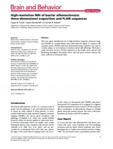
Fig. 1. Absolute position p is entirely identified by the pseudorandom code word {x(k)/k=n,...,1}
Pseudorandom code and its usage in encoders The method of pseudorandom encoding, which requires only one code track for absolute position determination, represents an attractive alternative to the classic measurement method. Its advantages are significant in the case of high-resolution position encoders and linear position encoders with very long code tracks. Coding is based on the “window property” of pseudorandom binary sequence (PRBS) {S(p) / p = 0, 1 ,..., 2n-2}. According to this, any n-bit code word {S(p+n-k) / k = n,...,1} obtained by a window of width n {x(k) / k = n,...,1} scanning the PRBSs, is unique and may fully identify window’s absolute position p relative to the beginning of sequence, fig. 1. As shown on fig. 1., code words are now arraying linearly or longitudinally (but not transversely as in the case of classic coding), and they overlap. The first (n-1)
RESET
Parallel code reading using the linear photodetector array It is necessary to apply any kind of parallel code reading method in order to realize a true pseudorandom absolute encoder, that way avoiding a need for initial movement. A possibility for application of integrated photodetector arrays is considered in this paper. Commercial integrated photodetector arrays are available on the market with different intervals between photodetectors. Those intervals are 13µm, 10µm, 7µm and smaller. A number of photodetectors can be few thousands, thus few tenths of sensors are used for one bit reading. Because of an exactly defined interval between two detectors, it is possible to use large number of photodetectors in order to increase absolute position measurement precision. A solution presenting basic principles of so far known solutions for parallel reading using linear photodetector array is shown in references [1], [11]. A code track of transparent type is applied, so that there is a light source at one side and an integrated circuit at the other, which consists of a linear photodetector array. This integrated circuit often offers a possibility for serial reading of photodetector output signal. When circuits with k photodetectors are applied, a state read after k tact pulses is put into the shift register. Let us read (n+c) bits and let nominal value of photodetectors number per one code bit be m. n is a number of bits needed for detecting the absolute position. Usually, at least one additional bit is read, and generally c additional bits. This way system redundancy is increased and use of some methods for detection of code reading error is enabled. A condition k≥ (n+c) m is always accomplished. Read code word is in the following form {00000111...1100 00111...1100....}. A transition is detected at the border of two elements. In the ideal case, a number of consecutive “1” or “0” per one bit equals m. A deviation may occur due to not ideal drift of code elements on code track. After the reading of total output code, its conversion into natural code is done. A generator of used PRBSs starts from the code word that corresponds to initial “0” position on the code track. Generator core is a shift register with appropriate feedback. With each tact that conduces generating of next PRBS byte, m tact from the shift register are performed. A code
STOP
CL
RESET
:m CLOCK
CL
CL
Sin
Sin
Fig. 2. High-resolution pseudorandom encoder with applied method of parallel code reading
bits of such code word are identical to the last (n-1) ones of the previous code word. Therefore, in contrast to transverse coding technique, which requires writing of a definite digital code in the transverse direction for each sector of code device, this method enables coding with one bit per sector. Otherwise, the longitudinal coding implies a use of cyclic codes. Pseudorandom code represents a special case
15
which is still not good enough for general-purpose encoders. Further in the paper, this idea will be elaborated and with some additional modifications, we will attempt to realize a solution where it is not necessary to define rough position for each new code reading.
identical to the one that would be read in the case of continuous MS movement from the position “0”, is obtained that way. In an ideal case, after a certain number of register shifts, a code word identical to the read one would be obtained. That correspondence could be simply detected by digital comparator circuit. A number of steps counted by a counter until the moment of correspondence represents output position information in the natural code. Unfortunately, as said before, an error would often occur in practice, and it is enough that one bit is read from (m+1) detectors and the PRBSs generator will not generate such code word, thus, a correspondence will not be detected. This is why a digital correlator is used, although it is a much complex solution, but it solves the problem, fig.2. Accuracy of the detected code is increased introducing a greater value for c. Accuracy of correlator output does not depend much on the accuracy of defining boundary locations of code elements. Let us observe the following example.
Complete solution algorithm without using permanent code reading during the MS movement A realization of the electronic encoder block using discrete electronic circuits is shown in fig. 2. Of course, the same function can be done using microprocessors and the appropriate software. Also, a realization using one modern programmable logical circuit is possible. An example of a possible algorithm realization of a new solution proposed here is shown in fig. 3. The basic idea is to exclude the digital correlator, separately from all the elements connected for the purpose of achieving any correlation function. Although digital correlators are well known and commercially available, in this case, they lead to a more complex system. In reference [11] it is pointed to a fact that with software realization, simpler techniques can be used rather than the accurate and precise mathematical correlative ones. Our goal is to achieve shorter time for PRBS reconstruction read from the track, and then use the well-known algorithm of pseudorandom/natural code conversion. The other idea does not consider constant determination of the rough position, but only for certain values of the fine ones. The fine position is defined by a number of rightmost photodetectors. This way, without using any arithmetical operations, a momentary position of the movable system is directly obtained, with the fine position resolution defined by the distance of two consecutive photodetectors in the photodetector array circuit. For example, for the used 10bit PRBS and for m = 64 (64 photodetectors per one bit), 16-bit output position information is obtained by means of direct linking of 10-bit code conversion result and 6 bits of smaller weight that define a number of photodetectors which detect next, not quite visible bit. As it is shown in fig. 3., a microprocessor defines the operation of photodetector array circuit using control signals. A reading of the recorded PRBS sequence is done in a way that series of voltage levels, which indicate a light intensity on the corresponding elements of the photodetector array, is lead to the input of a comparator. That way, with a defined voltage level Vp, this series of voltage levels is converted to a series of logical “0” and “1” at the comparator output, that is then lead to a serial microprocessor port. Afterwards, the microprocessor does the functions according to the software whose algorithm is shown in fig. 4. Bits obtained this way are memorized and then analyzed. Memorized binary code word is in the form of {...000111...1111000...}, considering that m consecutive detectors are used for reading of one bit. However, as it is previously mentioned, it is possible that some deviations occur - {...0001011...1101000...}. Detector ordinals are then determined. Since nominal period (a number of detectors per one bit) is known, a difference of two consecutive detector ordinals is approximately dm,
Fig. 3. An example of an encoder realization using a microprocessor
Let the distance between code element locations be 0.5mm and let the 11-bit PRBS (2047 quantization steps) be applied. In this case, a measurement range of 1m is realized. Now, let the distance between code elements be 10µm, which means that for the range of 1m, 100000 positions are required. This could be achieved using a 17bit code. At least (17+1)10µm=180µm of code track should be read by photodetector array. An optical system for enlargement of the figure can be applied here. If the figure is enlarged 10 times, a photodetector circuit of at least 1800µm is required. If distance of 10µm between detectors is satisfied with an array of 256 photodetectors, total space resolution is now 1µm. In the worst case, the shift register connected to the PRBS generator, should make 10x100000 shifts until the moment it detects the correspondence. It is altogether 0,1s at the tact of 10MHz, i.e. 100ms. That makes the boundary work frequency of the system 10Hz, which is inadmissibly small even for general purpose encoders. In the reference [11] it is pointed to a possibility that a classic pseudorandom/natural code conversion is done using a simple digital comparator. Additional fine position could be defined based on the detected, defined transitions. Using this procedure, measurement time would be reduced, 16
d={1,2,..., n}. All deviations greater then this one can be updated, but the periods between the transitions will be different afterwards. There are other reasons why they will be different from nominal period, but those deviations must not be great. In any case, a calculation of period mean value is proposed here. In the ideal case, obtained mean period (meaning the integer part of the mean value) will be equal to the nominal period. In reality, there will be deviations, and if they are greater than the proposed value k, the user should be informed. The system can track down those deviations and perform diagnostics in the part of additional functions. Based on the estimated mean period, certain corrections are eventually performed and the detector ordinals are determined. Fine position is now simply evaluated as a number of detectors that are outside of the last determined transition. The MS movement direction is determined based of the previous value of the fine position. When the boundary between bits is known, it is easy to perform the reconstruction of the read part of PRBS and then the pseudorandom/natural code conversion. The value of the rough position is that way determined. Since the rough position has the same values for a great number of simultaneous code readings, there is no need for permanent performing of this, according to the necessary time, the most important part of the algorithm. Initial idea about the moment of rough position determination, which is completely logical, imposes as the natural first one, and considers rough position determination whenever the fine position equals 0. However, detail elaboration of this idea indicates various additional problems. Firstly, during the MS movement to the left, the next fine position value is m-1, and it is necessary to decrease the rough position value by one. This correction of position value by one is a well known problem which occurs in the case of all parallel code reading methods, and it is solved by implementing correction logic as shown in [6]. Additional problem is that the correction is not to be done always, but only in specific moments. All this could be solved, but the complication of the algorithm would be significant, and it would even be necessary to record the preceding fine position value. Secondly, it is possible, for some reason, to skip value fine position=0, which way the rough position determination would also be skipped. Naturally, detection of this kind of situation would further complicate the proposed algorithm. A solution, which in a very simple way avoids mentioned problems, is proposed in this paper. Simply, the idea considers the rough position determination whenever the leap of fine position occurs (for example, fine position leap is greater than k). Let us now analyze system performance. During the MS movement to the right, the fine position leaps from value “fine position = m-1” to “fine position = 0”. When the leap is detected, the fine position will equal 0, and the rough position will be determined then, which is identical to the above-described approach. However, during the MS movement to the left, the fine position leaps from value “fine position = 0” to “fine position = m-1”. The rough position is now determined for the value “fine position = m-1” and will be decreased by one relative to the case when it is determined for the value “fine position = 0”.
START
P=0
READING OF THE DETECTOR ARRAY OUTPUTS
MEMORIZING OF READ BITS P=1
DETERMINING OF THE PHOTODETECTOR ORDINALS WHICH DEFINE TRANSITIONS
MEAN PERIOD DETERMINING