3Dept. of ECE, CR Reddy College of Engineering, Eluru, AP, India. Abstract ....
length L specified by the coefficients h0, . . . , hL−1 2 R, the corresponding Yi is
given by ..... Permutation vectors for m = 3 and the resulting 2m possible parity
types are ... Hyderabad Institute of Technology & Management (JNTUH) in. 2010
.
IJECT Vol. 5, Issue Spl - 3, Jan - March 2014
ISSN : 2230-7109 (Online) | ISSN : 2230-9543 (Print)
High Speed Channel Coding in Digital Communication 1
N Srikanth, 2B.Maheswara Rao, 3Dr. M Siva Ganga Prasad
Dept. of ECE, NRI Institute of Technology, Agiripalli, Vijayawada, AP, India Dept of ECE, Khammam institute of Technology & Science, Khammam, AP, India 3 Dept. of ECE, CR Reddy College of Engineering, Eluru, AP, India 1
2
Abstract While channel coding is a standard method of improving a system’s energy efficiency in digital communications, its practice does not extend to high-speed links. Increasing demands in network speeds are placing a large burden on the energy efficiency of high-speed links and render the benefit of channel coding for these systems a timely subject. The low error rates of interest and the presence of residual inter symbol interference (ISI) caused by hardware constraints impede the analysis and simulation of coded highspeed links. Focusing on the residual ISI and combined noise as the dominant error mechanisms, this paper analyzes error correlation through concepts of error region, channel signature, and correlation distance. High-speed links typically refer to backplane or chip-to-chip interconnects that operate at very high data rates ( 10 GBPS), low bit-error rate (10−15) and with high energy efficiency. The high-speed links form an integral part of many systems and their limitations thus generally have wide-ranging repercussions. Following the motivation, the high-speed link is re-introduced in a more abstracted form: that of a communication system with inter-symbol interference (ISI) and Additive White Gaussian Noise (AWGN). Keywords Digital Communication, HSCC, AWGN, Inter-symbol Interference I. Introduction This thesis explores the benefit of channel coding for high-speed backplane or chip-to -chip interconnects, commonly referred to as the high-speed links. High-speed links are ubiquitous in modern computing and routing. In a personal computer, for instance, they link the central processing unit to the memory, while in backbone routers thousands of such links interface to the crossbar switch. Arising from the critical tasks they are designed to perform, highspeed links are subject to stringent throughput, accuracy and power consumption requirements. A typical high-speed link operates at a data rate on the order of 10 GBPS with error probability of approximately 10−15. Given the bandwidth-limited nature of the backplane communication channel, the ever-increasing demands in computing and routing speeds place a large burden on high-speed links. Specifically, high data rates exacerbate the inter-symbol interference (ISI), while the power constraints and the resulting complexity constraints limit the ability to combat the ISI. As a result, the system is no longer able to provide the required quality of communication. In fact, this residual ISI limits the achievable link data rates to an order of magnitude below their projected capacity. The benefits of the regime classification also extend to system simulation, by allowing for more efficient simulation methods tailored for different regimes. In particular, this thesis develops the following results: • A more complete characterization of error mechanisms occurring in a high-speed link. This enables the classification of system’s operating conditions based on the dominant error mechanism as one of three possible regimes, namely, w w w. i j e c t. o r g
•
•
•
•
the large-noise, the worst-case-dominant and the large-setdominant regimes. A deeper characterization of codes for high-speed links. For instance, a characterization of error mechanisms allows identifying the conditions under which standard error control codes incur little or no performance impairments due to the residual ISI. Note that these include, but are not limited to, the cases where the ISI is relatively weak compared to the noise. A new approach to coding under the worst-case-dominant regime where error is principally due to the occurrences of certain symbol patterns. The resulting codes, termed the pattern-eliminating codes provide the benefit of low complexity, allowing for simple encoding and requiring virtually no decoding. A theoretical framework for interpreting previouslydocumented experimental behaviors, such New simulation methods for coded or uncoded high-speed links. The regime classification provides a more accurate guideline for biasing the system parameters in simulation to capture error behaviors at low probabilities. An efficient numerical algorithm for computing marginal probability distributions in a coded system. However, implementing standard error-control codes in the quasi-worstcase-dominant regime generally leads to a negative result, as in the case of ,or an inconsistent result, as reported in this thesis further examines the behavior of standard error-control codes in this regime and shows that for uncorrelated channels, where the notion of correlation is redefined through nesting of the worst-case symbol patterns, a single parity check code is optimal, as long as the codeword length is inferior to the correlation length..
II. The High-Speed Link: the Reality and the Motivation The increasing demands in network and processing speeds have placed a large burden on high-speed links, as it is becoming increasingly difficult to keep up with the increasing data rates while maintaining the same reliability and adequately low power consumption. Referring again to the part played by high-speed links in backbone routers, [4] cites the following relevant example. Consider the result of using current technology to create a 40 Tb/s crossbar router chip. Since cross-bar router switches currently support 1 Tb/s, striving to reach the 40 Tb/s mark is a realistic goal. To achieve that throughput, 4000 of the current 10 Gb/s transceivers would have to be deployed. Since each transceiver uses a differential pair, the switch chip would need 8000 I/O pins, thus requiring the total on-chip area of 4000 mm2. The resulting switch card would be roughly 4 meters (160 inches) wide and 2.5 meters (100 inches) long. Furthermore, since each transceiver currently dissipates 40 mW/Gb/s, the power consumption for the crossbar chip would total 1.6 kW, an unrealistically large number. A. High-speed Link as a Communication System The three principal error mechanisms in high-speed links, as International Journal of Electronics & Communication Technology 61
IJECT Vol. 5, Issue Spl - 3, Jan - March 2014
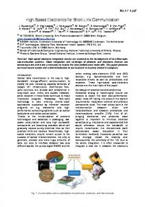
described in [6] are interference, noise, and timing jitter. The interference in high-speed links is due to both the Inter-Symbol Interference (ISI) and the crosstalk. The ISI is principally the result of the dispersion, due to the fundamental loss mechanisms in the wire, including skin effect and dielectric loss, and the signal reflections off of impedance discontinuities. Crosstalk, which can also be considered as co-channel interference (CCI), is due to multiple signals traveling through the same backplane. The effects of both the ISI and the CCI on the received signal can be described through the convolution of the channel impulse response, sampled at symbol times, with the history of the transmitted symbols. Noise in high-speed links is typically small with respect to the signal magnitude. It is principally ascribed to thermal noise and transistor device noise, and is therefore modeled as additive, white and Gaussian (AWGN) with standard deviation in the range of 3 mV down to 0.3 mV approximately, where the transmitted signal swing is ± 1V. The timing jitter is tied to the transmitter phase-locked loops (PLL) and the received clock data recovery (CDR) circuits. Various jitter models are available and many are overviewed in [6]. Since the ISI has been identified as the dominant error mechanism in a high-speed link [5], this thesis focuses on ISI-limited channels with AWGN. • The resulting simplified model of a typical high-speed link as a communication system is shown in Fig. 1. The system employs PAM2 modulation and the equivalent communication channel is discrete. The latter also includes the effects of any signal processing in the transmitter or the receiver, such as equalization or matched-filtering.
Fig. 1: Model of High Speed Link as a Communication System •
62
Due to the practical limits of equalization in high-speed links, the equalized channel response typically contains some amount of residual inter-symbol interference. Due to hardware complexity constraints, the detection scheme at the receiver is a blind application of the symbol-by-symbol maximum a posteriori (MAP) detection [3] for channels without ISI, rather than a more complex sequence detection scheme, such as [26], developed for channels with ISI. Concerning notation, it is convenient to denote the received signal at some time index I as Yi and represent it as the sum of a signal component Zi and the noise component Ni. Note that, throughout this thesis, upper-case notation is used to represent random variables, while the lower-case notation denotes the corresponding realizations and other deterministic quantities. The exception to this rule is the length of the channel response, denoted by L in order to be distinguished more easily from the ubiquitous time index I. Thus, for a channel of length L, the signal component Zi is given as the sum of the current symbol and the L − 1 previously2 transmitted symbols, weighted by the channel coefficients. The value z such that when Z = z the signal suffers no ISI is referred to as the signal mean, despite the fact that for constrained (coded) symbols z may not equal the expectation of the random variable Zi. Given a sequence of transmitted symbols Xi, . . . , Xi−L+1 2 {−1, 1}, where Xi is transmitted last, and some equivalent channel response of International Journal of Electronics & Communication Technology
ISSN : 2230-7109 (Online) | ISSN : 2230-9543 (Print)
length L specified by the coefficients h0, . . . , hL−1 2 R, the corresponding Yi is given by
Since, Yi is discrete, its marginal probability distribution is specified by the probability mass function (PMF), denoted by fYi , or alternatively, by the cumulative mass function (CMF), FYi . For a communication channel with ISI, the dependencies between the received symbols resulting from the convolution equation (Eqn. 2.1) imply that the set of marginal distributions fYi , . . . , fYi+L−1 is typically not sufficient to specify the joint distribution fYi,...,Yi+L−1 . However Chapter 2, among other results, describes some special circumstances under which the joint and the marginal distributions are effectively interchangeable. B. Classification of Error Mechanisms in High-speed Links Typically, the dominant error mechanism is loosely defined as the most likely source of detection errors. For instance, [6] observes that the intersymbol interference, rather than noise alone or the timing jitter, is the dominant error mechanism in a high-speed link. In the present context, however, the term takes on a more precise meaning. Specifically, the dominant error mechanism refers to an attribute of a set of interference events which are found to be responsible for some large proportion of the detection errors. The large-set-dominant scenario encompasses the remaining conditions, but also allows for a general result regarding joint error behaviors. C. Quasi-worst-case-dominant Scenarios While the previous development concerns the regime where the worst-case interference is responsible for most of the error events, such a behavior is seldom observed in practice. Instead, a more common occurrence is that of a dichotomous channel. The term refers to any channel of length L whose l coefficients are more significant than the remaining ones.
Fig. 2: A Dicho Tomous Channel Note that, in general, the l coefficients need not occur consecutively, nor be restricted to a specific portion of the channel. By considering an equivalent channel of length l, the previous characterization of the worst-case behaviors extends to worst-case interference caused by the principal part of the channel. The corresponding regime is referred to as the quasi-worst-case dominant regime and is illustrated in fig. 5 for a two-level channel. In this example, the principal part of the channel has length l = 5, signal mean z = a and interference coefficients of magnitude b, while the secondary part of the channel has coefficients of some lesser, unspecified magnitude. The plot illustrates only the a priori probability w w w. i j e c t. o r g
ISSN : 2230-7109 (Online) | ISSN : 2230-9543 (Print)
distribution of the random variable Zi and highlights the events that aggregately dominate the a posteriori probability. The latter correspond to all the events associated with the worst-case patterns ±(−1, 1,−1,−1) formed by the principal part of the channel and producing signal values centered at a − 4b. D. Large-set-dominant Regime The large-set-dominant regime is principally considered as a default regime for all the cases that, in a given context, do not fit the two other regimes. For instance, it can be used to classify the behaviors illustrated in fig. 2 (a - b) and, depending on the context, 1-2 c - d). It also applies to the conditions of fig. (1-4), where the system does not operate in either the worst-case or quasi-worstcase-dominant regime due to the negative decision distance. III. Coding For High-Speed Links Most modern communication systems employ some form of coding as a technique to improve the quality of communication. These often include redundancy-based error control codes that allow for error detection or correction, run-length-limiting codes that improve the receiver’s clock recovery, or DC-balancing codes that protect the timing circuitry against capacitative coupling. While inter-symbol interference (ISI) has a limited effect on the timing properties of a code, the performance of error control codes is significantly impaired, as demonstrated in [4]. The corresponding results provide conditions under which standard error-control codes perform optimally1 and, otherwise, lead to a new approach to error-control coding for the worst-case dominant or quasi-worstcase-dominant regimes. A. Preliminaries This section overviews the basics of error-control coding and extends the previously described high-speed link model to include coded transmissions. Previous work regarding coding for highspeed links is overviewed as well. • Error-control Coding • System Model
IV. Performance Estimation of Coded High-Speed Links The task of simulating a coded high-speed link is plagued with difficulties. The low error rates, typically on the order of 10−15, render Monte Carlo simulation strictly infeasible, even at today’s computing speeds. biasing the system’s operating parameters to inflate the frequency of the error events may change the corresponding interference-and-noise regime and therefore fundamentally change the system’s behavior in response to a code. For instance, an increase in the noise variance steers a system away from a (quasi-)worst-case- dominant regime and therefore renders a pattern-eliminating code ineffective. A. Algorithm Description When the set of allowed symbol sequences is restricted, straightforward enumeration provides a simple approach to w w w. i j e c t. o r g
IJECT Vol. 5, Issue Spl - 3, Jan - March 2014
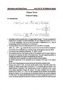
calculating the probability mass function for the probability mass function fWi of the random variable Wi defined previously. Possible values of Wi are obtained by considering each element of the codebook individually. An (n, k) code allows for 2k possible codeword’s, each n symbols long. Translating the resulting n-long possible symbol patterns into signal values using Equation 2.1 and noting that the patterns are equally likely yields a probability distribution. The size of the resulting probability mass function can be reduced by quantizing the possible signal values to some precision _ and adequately grouping the corresponding probabilities. This mechanism is illustrated in fig. 3-2 for a simple (3,2) single parity- check code with _ = 0.1. While the above method is adequate for dealing with
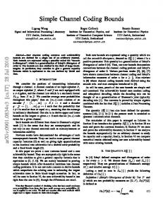
Fig. 3-2: Example: Signal contribution due to one previously transmitted codeword a) The corresponding portion of the channel response. b) The allowed symbol patterns. c) The resulting PMF. d) The quantized PMF. codeword’s of relatively short to moderate lengths, it quickly becomes burdensome as the number of independent bits in a codeword increases. For instance, computing the probabilities associated with a codeword of k = 100 information bits and any number m of dependent bits over a realistically long channel6 requires considering 2100 _ 1030 distinct possibilities. In order to handle arbitrarily long codeword’s, it is therefore necessary to reduce the enumerative burden of the method. This is illustrated in fig. 3-3 for a (7,4) Hamming code. For ease of representation and without loss of generality, the subsequent development assumes that the information is subdivided into even, consecutive blocks of d < k symbols.
Fig. 3-3: Example: Partitioning a (7,4) Hamming codeword for d = 2 – a) The original codeword. b) Two subcodewords. c) The portions of the generator matrix associated with each sub codeword. The algorithm now reduces to the following three steps. 1. Computing the partial information for each sub codeword efficiently. 2. Grouping partial information to reduce storage requirements. 3. Combining partial information from each sub codeword. International Journal of Electronics & Communication Technology 63
IJECT Vol. 5, Issue Spl - 3, Jan - March 2014
More precisely, defining the relevant sub codeword information as • The contribution of the d information bits to the received signal; • The contribution of the m parity bits to the full codeword parity. The corresponding vector elements tj , for j = 0, . . . , 2m − 1, indicate the number of the information symbol patterns, out of the 2d possible patterns, yielding the signal
Fig. 3-4: Example: The motivation for grouping sub codeword information vectors with identical signal values– a) The sub codeword and the corresponding portion of the channel response. b) The combinatorial expansion and the signal/parity vectors. c) The quantized signal/parity vectors where the quantization step is _ = 0.1. As expected, there are C1 2 = 2 vectors associated with w = 0. The combining is a two-step process. First, two subcodewords, each associated with d information symbols, are combined to yield the equivalent partial information for the resulting 2d symbols. Second, once all the subcodewords are
Fig. 3-5: Example: Grouping several signal/parity vectors with the same signal value – a) Possible parity types for k = 2. b) Transforming two signal/parity vectors to reflect their parity patterns. c) Grouping the vectors into one coordinate. combined, it suffices to transform the resulting parities into signal values and convert the information given in the coordinate form into the typical signal/probability representation. In other words, assuming the partial information for two subcodewords is composed of M and N coordinates respectively, the equivalent contribution of 2d information symbols results in M × N coordinates. Note that these need not be distinct, so the combining step is again followed by grouping coordinates with identical signal values.To better describe the basic combining principle, it is convenient to briefly revert to the original signal/parity vector representation, prior to any grouping. A given pattern of d independent bits from
64
International Journal of Electronics & Communication Technology
ISSN : 2230-7109 (Online) | ISSN : 2230-9543 (Print)
sub codeword r produces a signal contribution wr and a parity state (br1, br2, ..., brm)T . To obtain the equivalent contribution of the 2d information symbols to both the received signal and the parity, it suffices to add individual d-symbol contributions in both the parities and in the signal values, making sure to define the notion addition with respect to the underlying field. An example of the combining principle on the signal/parity vectors is shown in Figure 3-6 for a simple single parity check code.
Fig. 3-6: Example: Combining two signal/parity vectors corresponding to two different subcodewords to yield the equivalent signal/parity contribution – a) The original subcodewords with d = 2 implementing a single parity check code (SPC). b) The equivalent sub codeword with 2d information symbols implementing the same single-parity check code. In all three cases, the signal/parity vector has only two elements, associated with the signal contribution and the contribution to the single parity bit, respectively. The corresponding values are highlighted for clarity. Extending the above result to the grouped coordinate representation relies on the fact that there are 2m distinct combinations that can produce a given parity pattern. For instance, a pattern (b1, b2, b3) = (0, 0, 0), i.e. the parity of type 0, can be obtained by combining (0, 0, 0) with (0, 0, 0), as well as (1, 1, 1) with (1, 1, 1), or in general by combining any two identical parity patterns. Similarly, the parity pattern of type 1 is produced when combining any two patterns (br,1, br,2, br,3) and (bs,1, bs,2, bs,3) such that (br,1 _ bs,1, br,2 _ bs,2, . . . , br,m _ bs,m) = (0, 0, 1). The general result can be formalized as follows. Define the distance d : {−1, 1}m×{−1, 1}m 7! N between two patterns as d((br,1, br,2, br,3), (bs,1, bs,2, bs,3)) = dec(br,1 _ bs,1, br,2 _ bs,2, . . . , br,m _ bs,m) where the dec operator converts an unsigned binary string into its equivalent decimal integer representation. Then, a parity pattern of type j, where 0 _ j _ 2m − 1, is produced by combining any two patterns at a distance j from each other. Since following the grouping of the signal/parity vectors, each resulting coordinate may be associated with more than one parity pattern, when combining two coordinates from distinct subcodewords it is necessary to consider all the parity combinations which yield a given type. From Eqn 3.9, it is apparent that for any type j and any pattern b, there is a unique counterpart b0 such that b _ b0 = bin(j), where bin operator translates an integer taking values in the range {0, . . . , 2m − 1} into an unsigned binary string of length m. Given some parity type j, the ordered set of such counterparts, or, more precisely, of their decimal equivalents, is termed the permutation vector for type j, w w w. i j e c t. o r g
ISSN : 2230-7109 (Online) | ISSN : 2230-9543 (Print)
denoted Ij . For reasons to become apparent shortly, the ith element of the permutation vector Ij is given by Ij(i) = dec(bin(i) _ bin(j)) for i = 0, 1, . . . , 2m − 1 , where _ is the bit-wise xor operator. Permutation vectors for m = 3 and the resulting 2m possible parity types are shown in Table 3.1. This choice of terminology is indicative of each permutation vector’s purpose. More precisely, consider the combination of two signal/parity coordinates tr = (tr,0, tr,1, . . . , tr,2m−1)T associated with wr with ts = (ts,0, ts,1, . . . , ts,2m−1)T associated with ws corresponding to codeword’s r and s respectively. Then, the number of resulting patterns of type 0, denoted by trs,0 , is given as trs,0 = tTr ts. In other words, the result is an inner product of two parity vectors. Extending this principle to other parity types is achieved by preceding the inner product by a vector permutation. Specifically, the number of resulting patterns of type j is given by: trs,j = tTr× Pj × tr (3.10) V. Simulation Results
IJECT Vol. 5, Issue Spl - 3, Jan - March 2014
References [1] G. D. Forney,"Digital Communications II (6.451) Lecture Notes", M.I.T. (available at ocw.mit.edu). [2] W. C. Huffman, V. Pless,"Fundamentals of Error-Correcting Codes", Cambridge, U.K.: Cambridge University Press, 2003. [3] J. G. Proakis,"Digital Communications", 4th ed., New York, New York: MacGraw- Hill, 2000. [4] M. Lee,“Channel-and-circuits-aware Energy-efficient Coding for High-speed Links”, S.M. thesis, Massachusetts Institute of Technology, 2006. [5] V. Stojanovic, A. Amirkhany, M.A. Horowitz,"Optimal linear precoding with theoretical and practical data rates in high-speed serial-Link backplane communication”, IEEE International Conference on Communications,June 2004. [6] V. Stojanovic, M. Horowitz,“Modeling and analysis of highspeed links”, IEEE Custom Integrated Circuits Conference, pp. 589-594, Sept. 2003. [7] A. Ho, V. Stojanovic, F. Chen, C. Werner, G. Tsang, E. Alon, R. Kollipara, J. Zerbe, M. Horowitz,“Common-mode backchannel signaling system for differential high-speed links”, in Symposium on VLSI Circuits. Digest of Technical Papers., June 2004, pp. 352-355. [8] J. Zerbe,“Design, equalization and clock recovery for a 2.5-10gb/s 2-pam/4-pam backplane transceiver cell”, IEEE International Solid-State Circuits Conference, February 2003. [9] J. Ren, M. Greenstreet,“A unified optimization framework for equalization filter synthesis”, In Design Automation Conference, pp. 638-643, 2005. [10] A. Bessios, W. Stonecypher, A. Agarwal, J. Zerbe, “Transitionlimiting codes for 4-pam signaling in high speed serial links”, In IEEE Global Telecommunications Conference, December 2003, pp. 3747-3751.
G.Erna,ECE Dept Mother Teresa institute of science and technology Khammam district.M.Tech(VLSI-SD)-FromSITAMSChittoor(JNTUH) in 2008.His interested area’s are Digital Design,Low Power VLSI Design,Analog VLSI Desgin,FPGA Technology, communication,Signals and systems Mr. BHUKYA MAHESWARA RAO He has completed his B.Tech in ECE from – Sri Raja Rajeswari Engineering College-Karepally Khammam (JNTUH) in 2006 and ,M.Tech(VLSI-SD)-From Hyderabad Institute of Technology & Management (JNTUH) in 2010 .His interested area’s are Digital Design,Low Power VLSI Design,Analog VLSI Desgin,FPGA Technology
VI. Conclusion Modeling a high-speed link as an ISI-limited system with additive white Gaussian noise allows for an abstracted framework suitable for a more theoretical approach to studying the benefit of coding for high-speed links. Possible error mechanisms are categorized according to three regimes the large-noise, the large-set-dominant and the worst-case-dominant which are entirely specified by the system’s noise level and the channel’s pulse response w w w. i j e c t. o r g
Mr.BANOTH KRISHNA He has completed his B.Tech in ECE from –Dr.Paul Raj Engineering College-Bhdrachalam(JNTUH) in 2005 and ,M.Tech(VLSI-SD)-From SITAMS-Chittoor(JNTUH) in 2008.His interested area’s are Digital Design, Low PowerVLSI Design,Analog VLSI Desgin,FPGA Technology.
International Journal of Electronics & Communication Technology 65