International Journal of Smart Home Vol. 11, No. 9 (2017), pp. 1-8 http://dx.doi.org/10.21742/ijsh.2017.11.09.01
Home automation using IOT application Gaurav Panwar1, Rajat Maurya2, Rajesh Rawat3, Rohit Kanswal4 and Praful Ranjan51 1-5
THDC Institute of hydropower Engineering &Technology,Tehri, INDIA
[email protected] Abstract
Home automation is a topic which gaining popularity day by day, because of large advantages. One can achieve home automation by simply connecting home appliance electrical devices to the internet or cloud storage. the reason for this surge demand of network enabled home automation is reaching the zenith in recent days for its simplicity and comparable affordability. Platforms based on cloud computing help to connect to the things surroundings everyone so that one can find it easy to access anything and everything at any time and place in a user friendly manner using custom defined portals. Hence, cloud act as a front end to access IOT. Here we are assuming a system which can control devices through wireless based network or cloud based approach. In project we use IOT based home automation system which goal is to develop a home automation system that gives the user complete control over all remotely controllable aspects of his or her home. The automation system will have ability to be controlled from a central host PC, the internet, and also remotely accessed via a packet PC with a windows mobile based application. Keywords: Automation, IOT, Relay, Arduino
1. Introduction The home animation is control of home device form a central control point automation is today s facts where more things are being completed every day automatically. Usually the basic tasks of turning on or off certain device and beyond, either remotely or in close proximity. The concept of the RF-based system is to use the underlying wireless data network such as IEEE 802.11 (Wi-Fi). The popularity of wireless networks at home has increased in recent years, and the advanced computer technology has made the personal digital device to commonly have the capability to communicate through the wireless network. Hence, it is suitable to use RF-based location determation system to estimate location of the personal digital device in a home environment with high data rate transmission, supporting multimedia application may be feasible in WLAN. One if the possible application is wireless network for home automation. Imagine a private home equipped with motion light temperature and other sensor actuators for opining the door dimming lights with a remote control as complex as setting up a network of items in your home (such as thermostat, security system lighting and appliances) that can be programmed using a main controller. The basic idea of home automation is to employ sensor and control system to monitor dwelling and
Article history: Received (May 12, 2017), Review Result (July 23, 2017), Accepted (August 18, 2017)
ISSN: 1975-4094 IJSH Copyright ⓒ 2017 GV School Publication
Home automation using IOT application
accordingly adjust the various mechanism that provide heat ventilation lighting and other service. The automated “intelligent” home can provide a safer more comfortable and more economical dwelling. In an intelligent home automation system there are many possible solution for how and form where to control the automation system and single device a user interface can be a computer-based system a mechanical switch a single light a loudspeaker with a microphone or a some kind of personal remote controller using normal PC, laptop or table PC by stand alone software or web-based user interface. In the near future all electronic appliances in a home will be networked [1][2]. The internet of things (IOT) is the network of physical objects or “Things” embedded with electronics, software, sensors and network connectivity, which enable these objects to collect and exchanging data. IOT allows objects to be sensed and controlled remotely across existing network infrastructure, creating opportunity for more direct integration between the physical world and computer based system, and resulting in improve efficiency, accuracy and economic benefits.
2. Contents 2.1 Hardware description ESP8266: Presently ESP8266EX is a chip with which manufacturer are making wirelessly networkable micro-controller modules. More specifically, ESP8266 is a system-on-a-chip (Soc) with capability for 2.4Ghz Wi-Fi (802.11b/g/n, supporting WPA/WPA2), generalpurpose input/output (16 GPIO), inter-integrated circuit , Analog-to-digital conversion (10bit ADC),serial peripheral interface(SPI), I2S interfaces with DMA(sharing pins with GPIO), UART(on dedicated pins, plus a transit only UART can be enabled on GPIO2). It employs a 32 bit RISC CPU based on the tensilica Xtensa L106 running at 80MHz. it has a 64KB boot RAM. External Flash memory can be accessed through SPI [3]. The modules: Various vendors have consequently created a multiple of modules containing the esp8266 chip at their cores. Some of these modules have specific identifiers, including monikers such as “Wi07c” and “ESP-01” through “ESP-13”, while other modules might be ill- labelled and merely referred to by a general description- e.g- “ESP8266 wireless transceiver”. ESP8266 based modules have demonstrated themselves as a capable, low-cost, networkable foundation for facilitating end point IOT developments. ESPressif’s official module is presently the ESP_wroom-02 [4]. The AI thinkers are succinctly labelled ESP-01 through ESP-13. NODEMCU boards extended upon the AI-thinkers modules. Olimex, ADAfruit, SPArkfun, WEmo
2
Gaurav panwar, Rajat maurya, Rajesh rawat, Rohit kanswal and Praful Ranjan
International Journal of Smart Home Vol. 11, No. 9 (2017), pp. 1-8
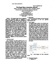
Figure 1. Circuit Connections of ESP module 8266 Relays: A relay is a simple electromechanical switch made up of an electromagnet and a set of contacts. Relays are found hidden in all sorts of devices. In fact, some of the first computers ever built used relays to implement Boolean gates. In this article, we will look at how relays work and a few of their applications. Relays are amazingly simple devices. There are four parts in every relay. Electromagnet, Armature that can be attracted by the electromagnet, spring, Set of electrical contacts which is shown in figure 2 & 3. A relay is an electrically operated switch. Many relays use an electromagnet to mechanically operate a switch, but other operating principles are also used, such as solid-state relays. Relays are used where it is necessary to control a circuit by a separate low-power signal, or where several circuits must be controlled by one signal. The first relays were used in long distance telegraph circuits as amplifiers: they repeated the signal coming in from one circuit and re-transmitted it on another circuit. Relays were used extensively in telephone exchanges and early computers to perform logical operations. A type of relay that can handle the high power required to directly control an electric motor or other loads is called a contactor. Solid-state relays control power circuits with no moving parts, instead using a semiconductor device to perform switching. Relays with calibrated operating characteristics and sometimes multiple operating coils are used to protect electrical circuits from overload or faults; in modern electric power systems these functions are performed by digital instruments still called "protective relays". Magnetic latching relays require one pulse of coil power to move their contacts in one direction, and another, redirected pulse to move them back. Repeated pulses from the same input have no effect. Magnetic latching relays are useful in applications where interrupted power should not be able to transition the contacts. Magnetic latching relays can have either single or dual coils. On a single coil device, the relay will operate in one direction when power is applied with one polarity, and will reset when the polarity is reversed. On a dual coil device, when polarized voltage is applied to the reset coil the contacts will transition. AC controlled magnetic latch relays have single coils that employ steering diodes to differentiate between operate and reset commands.
Copyright ⓒ 2017 GV School Publication
3
Home automation using IOT application
Figure 2. Types of relays
Figure 3. Relays used in prototype
Figure 4. Relays pin setup
4
Gaurav panwar, Rajat maurya, Rajesh rawat, Rohit kanswal and Praful Ranjan
International Journal of Smart Home Vol. 11, No. 9 (2017), pp. 1-8
3. Design & Implementation In the project we embedded the ESP8266 Wi-Fi module with sugar cube relays to control devices wirelessly or from particular distance. Here we use hotspot configurations, that to achieve our project goal, first of all we create a hotspot channel to connect other devices and so ESP8266 .Then when we configure the correct IP address which is generated by the software “Arduino.ide” for the other devices to connect. Remember the IP will be same cause the ESP module system is stable so the IP is always same [5].Here we use diodes in the circuitry of sugar cube relay arrangements to prevent the damages of back EMF which is generated by the coil of relay’s inner circuitry. The capacitors used to stable the charge for coil to stay in set state as shown in figure 5.
Figure 5. Overall circuit diagram
The Arduino Integrated Development Environment - or Arduino Software (IDE) - contains a text editor for writing code, a message area, a text console, a toolbar with buttons for common functions and a series of menus. It connects to the Arduino and Genuino hardware to upload programs and communicate with them. Programs written using Arduino Software (IDE) are called sketches. These sketches are written in the text editor and are saved with the file extension .ino. and shown in figure 6. The editor has National Conference of Communication systems and Advance Computingfeatures for cutting/pasting and for searching/replacing text. The message area gives feedback while saving and exporting and also displays errors. The console displays text output by the Arduino Software (IDE), including complete error messages and other information. The bottom right hand corner of the window displays the configured board and serial port. The toolbar buttons allow you to verify and upload programs, create, open, and save sketches, and open the serial monitor in figure 7.
Copyright ⓒ 2017 GV School Publication
5
Home automation using IOT application
Figure 6. Software simulation on arduino IDE
Figure 7.
4. Results After the successful connection to the server, the data of sensor are sent to the web server for monitoring of the system. The figure 4 shows the web server page which will allow us to monitor and control the system. By entering the assigned IP address in the web browser this web server page will appear. The web server gives the information about the temperature in different places of the house and motion state in the house. It also gives the status of the various electrical appliances like light, fan etc which we can control remotely.
6
Gaurav panwar, Rajat maurya, Rajesh rawat, Rohit kanswal and Praful Ranjan
International Journal of Smart Home Vol. 11, No. 9 (2017), pp. 1-8
5. Conclusion and future work The next phase for the home automation market will occur based on a few key improvements in the technology available in automation, such as improvements in wireless automation solutions as well as lowering of price points as the market begins to accept home automaton usage in larger volumes. Some trends that we foresee for this phase of the industry are Big companies like philips, Siemens & scheider will eventually bring out fairly mass market automation products with appealing user interface but at a lower price point today, and more people will be able to afford the products. Some foreign players will have niche in high and automation and focus fun the premium market.
Figure 8. Block diagram of application
Advantages
Error probability reduced Ease of access and low cost and power consumption Can reduce human effort Smarter processing and services Can be implemented at any device and automated Alert system is quick in case of an emergency Eliminates the use of PC for automation Helps old age people to control the remote devices Simple interface
Disadvantages
Replacing humans is dangerous May take time and learning Security concerns Vulnerable to attacks Most of the times range is restricted High dependency on sensor devices which makes the system vulnerable if sensor fails
Copyright ⓒ 2017 GV School Publication
7
Home automation using IOT application
References P. S. Pandey, P. Ranjan, M. K. Aghwariya, “The Real-Time Hardware Design and Simulation of Thermoelectric Refrigerator System Based on Peltier Effect” ICICCD 2016 DOI 10.1007/978-981-10-17087_66, Vol. 7, pp. 581-589, (2016). [2] G. Rani, P. S. Pandey, M. K. Aghwariya, P. Ranjan, “LASER as a Medium for Data Transmission Proceeding of International conference on” ICARE MIT-2016 9-11 DEC-2016 Organized by Department of Mechanical Engineering, M.J.P. Rohilkhand University, Bareilly-. ISBN No. : 978-93-82972-19-8. [3] P. S. Pandey, M. K. Aghwariya, P. Ranjan, G. Rani, “Designing of Tracking System And Emergency Vehicle Locator With UltraSensitive GPS Receiver Active Antenna” on National conference on Advancement in Engineering Materials(NCAEM-2016) M.J.P.Rohilkhand University, Bareilly, 24-25 Feb 2016, ISBN No.: 978-93-82972-12-9. [4] P. Ranjan, G. S. Tomar, R. Gowri, “Metamaterial Loaded Shorted Post Circular Patch Antenna” on International Journal of Signal Processing Image Processing and Pattern Recognition (IJSIP) SERSC Publication, ISSN 2005-4254, Vol. 9, No.10, pp 217-226, (2016) [5] P. S. Pandey, D.S. Chauhan, R. Singh, “The Real Time Hardware Design and simulation of moving message Display System Integrated with PLCC Modem” Innovative Systems Design and Engineering, ISSN 22221727 (Paper) ISSN 2222-2871 (Online), Vol. 3, No. 10, (2012). [6] Oudji, S., Courrèges, S., Paillard, J. N., Magneron, P., Meghdadi, V., Brauers, C., and Kays, R. “Radiofrequency Interconnection between Smart Grid and Smart Meters Using KNX-RF and 2.4 GHz Standard Protocols for Efficient Home Automation Applications”.Journal of Communications, Vol.10, No. 10, (2015). [7] Kumar, M., and Shimi, S. L. “Voice Recognition Based Home Automation System for Paralyzed People. System”, Vol. 4, No. 10, (2015) [8] A. N. Shewale, J. P. Bari. “Renewable Energy Based Home Automation System Using ZigBee” (2015) [9] Dey, S., T. Kundu, S. Mukherjee, and M. Sarkar. “Web Based Real-time Home Automation and Security System” (2015). [10] Amrutha, S., Aravind, S., A. Mathew, S. S., Rajasree, R., and Priyalakshmi, S. “Speech Recognition Based Wireless Automation of Home Loads-E Home. System”, Vol. 4, No. 1, (2015). [1]
8
Gaurav panwar, Rajat maurya, Rajesh rawat, Rohit kanswal and Praful Ranjan