model and is required to define the service infrastructure required to support the typical actions of the user. In addition they should be considered responsible to.
13
International Journal of ARM, VOL. 9, NO. 1, March 2008
HomeTL : a tool set to support service monitoring development Alberto Rugnone*, Chris Nugent** , Mark Donnelly** , Enrico Vicaro* and Cristiano Paggetti*** * Department of Systems and Computer Science, University of Florence, Italy **School of Computing and Mathematics and Computer Science Research Institute, Faculty of Engineering, University of Ulster at Jordanstown, Northern Ireland ***I+ s.r.l. Florence, Italy
Abstract The integration of intelligent technology into the home environment has become recognized as a means of providing higher levels of autonomy and independence for the aging population. Within this technology domain, an area of particular interest is in the development of the services offering the facility to monitor and react to contextual scenarios based on the information sampled from sensorised environments. To facilitate the definition of the set of rules upon which the monitoring service can react, healthcare professionals are consulted to define the specifications of scenarios and to profile user specific needs. This activity also requires technical expertise to design, implement and refine the set of rules which guide the context under which the technology operates. As a result healthcare professionals are unable to fully participate in the development of the service model. This has resulted in an emerging barrier between the coherence of the healthcare professional descriptions and the understanding of technology providers. The current work proposes a set of tools to reduce this barrier and involve the healthcare professionals in the development process. Initial results from a user evaluation suggest that such tools hold the potential for real world adoption in the process of designing and interpreting the set of rules used to govern an intelligent environment.
1. INTRODUCTION In an ever increasing elderly population [1], people
are beginning to taking greater interest in their own healthcare. This has resulted in the requirement to integrate intelligent technology into the home environment to provide higher levels of autonomy and offer a means of independent living [2][19]. Coupled with these trends is the requirement for reliable service models to provide the ability to monitor the technology in the home, process it, and form automated decisions based on the data collected. While such service models exist, they require technical expertise to design, implement and refine rule sets which guide the context under which the technology operates. As a result, healthcare professionals describing the conditions and scenarios under which the technology should function are unable to fully participate in the development of the service model. This has led to the emergence of a barrier between the expectations of the healthcare professional and the understanding of technology providers. In the current study, we present HomeTL which facilitates the design and implementation of the set of rules required to guide the context under which the technology within an intelligent environment operates. Specifically, a visual editor has been designed and developed so that healthcare professionals can be fully involved in the definition of the rules without requiring a high degree of computing skills. Consequently, using the concepts of temporal logic, the visually designed rules can be automatically transformed into a set of parameters for inclusion in the service model. The remainder of the paper is structured as follows: in Section 2 the background to the approach adopted is described detailing previous work conducted in the definition of meta-modeling for monitoring services. Particular attention is devoted to describing the actors involved in this activity and their inter-relationships.
Alberto Rugnone et al.: HomeTL : a tool set to support service monitoring development
In Section 3 the methods are described, while in Section 4 the suite of tools developed, referred to as HomeTL, is introduced and an analysis of the underlying mathematical language used is provided. Subsequently, the visual formalism derived, aiming at reducing the complexity of the underlying mathematical
14
formalisms is shown. Section 5 presents the results obtained following a usability study of the system. Finally, Section 6 concludes with a discussion relating to the initial impact of HomeTL based on the results obtained and describes the means by which the present work will be further developed.
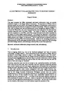
Figure 1 A Role Diagram defining the roles and the responsibilities assigned to each of the actors.
2. BACKGROUND Within the realms of home based care delivery, terms such as service model and care model are commonly used to represent the infrastructure through which care is managed and delivered. Generally, the purpose of such a monitoring system is to provide a platform from which, a patient's status can be remotely monitored and when required an appropriate intervention can be taken. Within such models, the stakeholders involved, their roles and responsibilities, and the links and interactions between them are defined in addition to a description of the collection of services and devices available for deployment. To date, several studies have been directed towards the deployment, and evaluation of monitoring services and devices [3][15][16][17][18], however, relatively little research has been focused towards the process of defining the set of rules under which the technology should function [4]. In particular, no process exists for interpreting the non technical
descriptions of these rules as provided by healthcare experts. Model Driven development practice has deployed the concept of a meta-model and meta-modeling [20] as methodological and technical approaches to implement software models based on a general schema of the context and of the problem under analysis. The current work borrows from the concept of metamodeling and attempts to fit an abstraction to a monitoring service model, which could be adapted on almost all elements related to it. This meta-model establishes all elements involved in the solution of a monitoring service, providing a description of the actors, processes and software nodes required to deploy a solution in any context.
2.1. Meta-Model Essentially, by applying meta-modeling to the concept of a monitoring service model it is possible to define the necessary contexts for patient monitoring
15
International Journal of ARM, VOL. 9, NO. 1, March 2008
within an intelligent environment. By subsequently providing a definition in such a manner, it then becomes possible to formalize a solution to manage the design and maintenance process.
2.1.1. The actors Figure 1 presents the service model under consideration. In total, four actors (stakeholders) may be represented: Healthcare Expert : refers to a medically trained expert who possesses the domain knowledge necessary to define the process of care and to describe the scenarios that must be catered for. The healthcare professional is primarily active in the “design” stage of the service model and is required to define the service infrastructure required to support the typical actions of the user. In addition they should be considered responsible to
describe the subsequent actions that the services should provide to support the user. During “run time” this actor is required to provide continual support in the refinement of the rules depending on the progress or decline of the patient’s health status. Operator : refers to personnel such as nursing staff, who monitor the person within their home during “run” time and in the first instance asses the feedback produced by the technology. User: describes the central subject for whom the services are being provided. They interact with the Human System Interfaces (HISs) provided within the environment and receive services according to their changing needs. Typically, such environments will consist of both sensor and actuator based technology.
Figure 2 Activity diagram showing the sequence of steps in the overall process as represented by three activities. General feedback is illustrated as requirements used to refine the products of the process.
Service architect : has the technical responsibility to develop the underlying service being offered. In addition, it is the role of the service architect to support the general maintenance and updating of the system and its rules. Following identification of the actors it is necessary to identify the activities of the Service Model which would be required to firstly acquire data from the subject in relation to their well being and secondly
acquire data relating to the activities they are performing. Based on this, the following can be identified: A means to process the data and provide a measure for the wellness state of subject. This should also provide a classification of the state of the patient such as Normal, Warning or Alarm and consequently, facilitate a means to personalize this classification in relation to the needs of the user on a case-bycase basis.
Alberto Rugnone et al.: HomeTL : a tool set to support service monitoring development
A means to provide a set of information to support the monitoring, analysis and forming of decisions based on the states observed. A way of providing the correct actions to carry out the decision made. At the core of such a monitoring service, should be the provision of a flexible tool to facilitate the personalization of the care monitoring rules. In a user centered approach, the specification of rules is undertaken through a scenario analysis to reinforce the understanding of a user’s needs. Therefore, the process of rule design must be disciplined and follow a proper methodology. In developing the service, the healthcare professional and the service architect are therefore required to work closely. The sequence that these actors participate in is outlined in Figure 2. In the requirements analysis, the user’s specific needs are collected and subsequently specified in the scenario analysis to guide the phase which governs designing the rules. This results in the definition of the set of rules required to govern the environmental configuration such as the sensor and actuator technology. In particular, the scenarios analysis is considered to be an activity which is performed by both the architect and the healthcare expert. The purpose of the scenario analysis is to define the environmental variables which are to be monitored.
They are essentially composed of a set of propositions which can be detected directly or by a pre-processing action on a sequence of states which are provided by a fetching layer, and in addition by a set of temporal constraints and relations between them. The meta-model provided encapsulates the high level solution from the architectural point of view by defining the layer of the service model and describing the components being developed. The architecture, presented in figure 3, is composed of three layers: Environment Layer : at this layer data is collected through a highly sensorised environment. The data collected is subsequently processed by the Processing layer within the meta-model. Examples of sensors range from motion detectors, having the ability to detect a person’s presence in a given room, pressure sensors which may be used to detect a person sitting in a chair, or lying on the bed, to water sensors used for detecting the flow of water. Processing Layer : at this layer the data collected in the environment layer is processed based on rules that are provided by the Decision layer. Processing the data provides feedback to the Decision Layer in the form of warnings or alarms relating to the state of the patient.
Figure 3 Deployment diagram defining the layers described by meta-model.
16
17
International Journal of ARM, VOL. 9, NO. 1, March 2008
Decision Layer : at this layer the system forms decisions and initializes the command to carry out the necessary actions to meet the user’s needs. The decision layer provides the actions at ‘run’ time with the associated rules being established previously at the ‘design’ time. Further modifications of the rules can take place during ‘run’ time to reflect the evolving needs of the patient. The decisions are essentially formed using the set of rules that are provided by the experience of healthcare providers. Figure 3 presents the deployment diagram of the meta-model nodes. Based on this diagram the current work focuses on the rule set and rule editor components.
It is proposed that the HomeTL concept provides a sufficient level of support during the scenarios analysis that collaboration between the service architect and the healthcare professional, reduces the aforementioned barrier between the expectations of the healthcare professional and the understanding of technology providers.
4. HOMETL HomeTL offers a language whereby the rules to Scenario
3. METHODS To effectively realize the concepts of the previously defined meta-model we introduce the concepts of HomeTL. HomeTL addresses two different elements of the meta-model. The first is the implementation of the tools which can be used to support the concepts of designing the rules (rules editor). These are the rules required to govern the monitoring service. The second is to define the algorithmic base which will be targeted for deployment in the processing layer (rule set). In the first instance the concepts of the tools and languages used to support both the design and maintenance phases of the HomeTL concept are presented. With these established, the algorithms for automatically processing the rules, and the monitoring platform which are required to capture the detected events are introduced. Finally, we present the details of a visual editor which can be used to capture the process of designing the rules. The design of the concepts presented within this study are based on an established number of typical scenarios as previously defined in [4] and investigated in [5]. Table 1, below, summarizes the five scenarios considered. All scenarios have been based on the premise that the environment within which the person will be living is highly sensorized. This will facilitate the monitoring and recording of the person’s interaction and movements throughout their home environment [2] in addition to providing a means of controlling the status of the environment.
Summary
Cooking
The cooker should not be switched on until the person has added some food to a pot and placed a pot on the cooker. The cooker should not be switched on for more than 1 hour.
Dressing
Once the person wakes and gets out of bed, within a specified time (30 minutes) it is normal that they first go to the bathroom and wash and then proceed to dress themselves. Both of these activities should be performed before the person leaves the house.
Grooming
Once in the bathroom the person should wash, brush their teeth and comb their hair. There is no desired sequence to these activities; however, the duration within which they should be completed would not normally exceed 30 minutes.
A person must take their medication within 2 hours after getting out of bed. Medication management Within this period they must also ensure that they have had something to eat prior to taking the medication.
Drink Preparation
The preparation of a drink should follow a general sequence of steps. For example, the kettle should not be boiled unless water has been added and the person should not consider the activity finished until they have added some milk or flavorings, tea/coffee and the boiled water to a cup.
Table 1 Exemplar User Scenarios
Alberto Rugnone et al.: HomeTL : a tool set to support service monitoring development
be used can be defined through the use of visual icons. Based on previous work [7], HomeTL defines the syntax with the semantics of language based on temporal logic. In addition, it provides a simple algorithm to compute the rules which compose the scenarios. In the first instance, the syntax and semantics of the temporal logic must be defined. To do this linear temporal logic in used [8][9][10]. Following the results of previous studies [6][7], we borrow some operators which have been defined for use when considering linear temporal logic and subsequently adapt the syntax and semantics to extend the expressivity and the flexibility of the previously defined language.
4.1. Temporal logic language The language of temporal logic relies on describing conditions over paths ( ), such as the sequences of states. A formula defining rules on a path is called a path formula. Path formulae are built as a combination of atomic propositions on states, by means of Boolean connectors and temporal operators (see Table 2) [7]. The temporal operators are “U”, “A”, “F”, “N”, “C”, and “()” to represent Until, Always, Future, Next, Counter, and Boundary, respectively. Using an index, , we can specify that formulae built by these operators are constrained within a temporal interval [0, ]. It is also possible to omit from the writing of a temporal operator, thus implicitly setting it to , and un-bounding the time interest interval of the operator. In order to enrich the expressivity and the flexibility of the mathematical notation we have added the possibility to use apex on the brackets. The semantics define all of the operators which can be used. Table 3 presents the temporal operators. (To reduce the complexity of the table the use of Boolean operators has been omitted.) Through the use of relationships and temporal constraints we can define the formula as presented in Table 3.
Table 2 Temporal logic syntax to be used. The proposition shown is the result of the combination of atomic propositions, by means of Boolean connectors and temporal operators.
18
Table 3 Temporal Logic Semantics In accordance with the solution derived from the meta-model, sequences received from the environment layer require a form of processing. To address the implied constraints related to both time and space complexity, a simple and incremental algorithm based on recursive evolution of two variables, called and T is presented to support the requirements of the behaviour checking.
where represents the validity of the formula to be checked, while T is a temporal evaluation on the sequence of states. If is true the formula satisfies the path which is currently being evaluated.
4.2 Example To provide an example of the aforementioned concepts the metaphor of CRC (Class, Responsibility, and Collaborator) cards may be utilized [14]. Based on the application of this metaphor, the definition of three elements is possible: Propositions : these can be considered to be similar to a class name and are the objects composing the scenarios. Temporal Relationship : similar to the concept of collaborations, these are used to define the relations between the propositions. Temporal Constraints : similar to responsibilities, they define the boundaries of a proposition. In order to maintain simplicity all concepts have been summarized using a PCR card (propositions, constraints, relationships). PCR cards are used to represent the specification of the scenarios and provide the subsequent starting point for the analysis to define the formulae. The analysis conducted by means of these cards permit the definition of a list of propositions. It is therefore possible to reiterate the analysis to allow the decomposition of the action as a set of scenarios represented in more elementary components. As an example, consider the scenarios based around the
19
International Journal of ARM, VOL. 9, NO. 1, March 2008
management of a patient’s medication as presented in Table 1. In the first pass of our analysis we can detect three main propositions as shown in Table 4. At this point, the analysis continues, with the definition of relations between each of the actions. By using an informal textual description, it is clear that the medication scenario is represented by a sequence of events. Nevertheless, although there is a sequence of events there is no clear sequential relationship between the events. In the PCR card the relations are therefore represented with the formalism “in the future”, indicated with the letter ‘F’. A final stage of temporal constraint analysis is applied. The duration within which the sequence of the activities should be performed should be included in the PCR table (for example 120 minutes in the current scenario). By adhering to these steps it is therefore possible to provide a more formal description of the scenario under consideration.
Table 4 An example of a PCR card used to capture the Proposition, Constraint and Relations from a scenario description
4.4. Visual Editor The HomeTL Visual Editor is a tool based on a simple set of formalisms which aims to facilitate the process of rule design. It is based on the usage of visual notations previously reported [6][7] and the extends upon the concepts proposed by the HomeCI interface [4]. It shifts the mathematical focus imposed by the temporal language towards a more intuitively based means of designing rules. As such, this approach offers an alternative to other methods such as the PCR card system. Using the HomeTL visual editor, the healthcare professional can define the set of rule formulas through a series of visual formalisms without having to understand the underlying computational principles of the temporal logic itself. The visual formalisms adopted, were designed following a previously conducted user-centered usability engineering process [6] applying practice of usability engineering [11][12] [13]. The basic visualization primitives associated with the semantic constructs of temporal progression, timing constraints, and propositional logic, can be combined into a set of visual rules which associate each terminal token of Linear Temporal Logic (LTL) with a graphical icon. Matching the recursive organization of the LTL syntax and semantics, these rules reduce the visualization of a formula to the recursive visualization of its sub-formulae and to the graphic icons representing terminal symbols. With this formalism in place, the HomeTL visual editor permits the selection of preconfigured icons to express atomic propositions.
Figure 4 HomeTL boolean connectors compared with original temporal logic formalism for boolean operators.
Alberto Rugnone et al.: HomeTL : a tool set to support service monitoring development
20
Figure 5 The original formalism based on temporal logic compared with the HomeTL formalism. The pictures describe the real application of the temporal operators.
Figure 6 Demonstration of adding the possibility to label a rule with a name, by means of group’s name operator were a boundary operator is defined to specify a temporal limit of a rule. The left hand picture shows a rule modeling the medication scenarios : within 2 hours, the patient has to take medication after meal time and meal time should be after get out of bed. The rule is marked as “medication” and can be reused with a rectangle representing itself.
21
International Journal of ARM, VOL. 9, NO. 1, March 2008
Figure 7 HomeTL Visual Editor. The visual notation in the centre of the screen represents the cooking preparation scenario.
4.4.1 User Interface The HomeTL visual editor, presented in Figure 7, was initially prototyped within Microsoft Visio to reduce the development time. Specifically, two addition stencils have been added to the Visio toolbar ; a stencil with a set of icons to define the events and, a second stencil presenting the temporal logic operators. In producing a prototype user interface for healthcare professionals in the given study, we based our developments specifically on the scenarios previously presented in Table 1. On the left hand side of the HomeTL visual editor user interface is the tool bar where users can select the events they wish to include in the design of the condition to be monitored. These events include for example ‘open door’ or ‘turn on kettle’. Along the bottom of the editor are the necessary symbols to support the construction of the HomeTL notation (as presented in Figure 7). Both the events and symbols can be selected and dragged onto the main canvas of the application. For the purposes of evaluation a timer was added to record the time taken to design each rule. The example
presented in Figure 7 is representative of the cooking scenario described in Table 1.
5. RESULTS In evaluating the HomeTL prototype, a limited usability test conducted on three users was designed adapting the usability test performed for HomeCI [4]. Specifically, the evaluation was conducted on computer scientists who were familiar with the use of technology to support healthcare. Although each user had experience in programming and computer science, none had experience in modeling with formal methods and none had an understanding of temporal logic theory. Prior to using the system, the users were provided with a short presentation outlining the goals of the HomeTL approach. Subsequently, a description of the constructs used to build rules for each scenario,
Alberto Rugnone et al.: HomeTL : a tool set to support service monitoring development
using the visual notation, was provided. This was then followed by a brief demonstration of the HomeTL visual editor which lasted approximately 10-15 minutes. The evaluation was based on the scenarios as presented in Table I and structured as follows: Scenario 1 (Cooking) : This example was shown to the users. The solution was constructed using HomeTL by the investigator who was conducting the evaluation. Scenario 2 (Dressing) : Users were shown the final solution on the HomeTL editor and asked to create the narrative. Scenario 3 (Grooming) : Users were given the narrative and asked to create the rules using the HomeTL tool. Scenario 4 (Medication Management) : Users were given the narrative and asked to create the rules using the HomeTL tool. Scenario 5 (Drink Preparation) : Users were given the solution on the HomeTL editor and asked to create the narrative. Following the evaluation, the users were asked a number of questions regarding the HomeTL interface and asked to score their response between 1 and 10 (1 poor, 10 excellent). The user responses to Scenarios 3, 4 and 5 were each assessed following the investigation. For Scenarios 3 and 4 each solution was assessed on 3 criteria : correct use of icons, correct use of notation and correct insertion of timing constraints. Each criteria was given a mark between 0 and 3. The time to complete both Scenarios 3 and 4 was also recorded. For Scenario 5 the narrative produced was assessed and scored as a percentage. As can be seen from Table 5 the average percentage scores for all Scenarios was 85.2%, with a minimum of 77.8% and a maximum of 100%. The results from the users in terms of their experience of using the tool can be found in Table 6.
6. DISCUSSION In order to ascertain the potential benefits of HomeTL, three computer scientists, active in research related to healthcare delivery, were recruited to evaluate the prototype editor. Following a limited period of
22
demonstration and training on the HomeTL editor, the volunteers were, independently, able to visually design two scenarios using narratives provided. Separately, the volunteers were able to produce highly accurate narratives for a further pre-designed scenario. Although the volunteers were provided with limited exposure to the prototype, prior to the evaluation, they expressed high levels of satisfaction with regards to being able to understand the design process, which was reported as being intuitive, and suggested the overall ease with which they were able to learn to use the tool. In terms of constructive criticism, some users reported difficulties in being able to recall all of the details surrounding the correct use of the notation, particularly the temporal operators “until” and “next”. They reported that this had affected their confidence in selecting the correct notation from within the design tool. Nevertheless, the results from the evaluation indicate that all user’s performed well in the tasks evaluated, with relatively few errors being noted, and all were able to complete the tasks within a reasonable period of time.
1
2
3
Avg.
Icons
2
3
2
2.3
Notation
3
1
3
2.3
Time
3
3
3
3
Total(%)
88.9
77.8
88.9
85.2
Time(s)
55
321
53
143
Icons
3
3
3
3
Notation
1
1
3
1.7
Time
3
3
3
3
Total(%)
77.8
77.8
100
85.2
Time(s)
134
337
130
200.3
80
90
90
86.7
Scenario 3
Scenario 4
Scenario 5 Narrative(%)
Table 5 Assessment of user interaction with HomeTL interface.
23
International Journal of ARM, VOL. 9, NO. 1, March 2008
1
2
3
Avg.
Overall experience
6
6
8
6. 7
Ease of using icons
8
6
8
7. 3
Ease of use of interface
8
8
10
8. 7
Ease to produce narrative
9
8
10
9
Usefulness of system
9
6
10
8. 3
Table 6 User’s experience in using the HomeTL prototype
7. CONCLUSION The Home TL editor is proposed as a tool to facilitate the visual representation of the set of rules required to support a service model for monitoring an intelligent environment. The results attained following an evaluation suggest that there is a potential benefit in introducing such a tool to reduce the barrier which exists between healthcare professionals and service architects. A perceived limitation is that the evaluation of the visual editor was conducted on computer scientists instead of healthcare professionals. Nevertheless, the feedback obtained has raised some interesting questions which could be used to guide future development of the tool. One interesting aspect relates the difficulty in fully understanding the visual notation. A future challenge therefore exists to further simplify the visual notation available in the visual editor whilst maintaining the function to automatically generate the set of rules based on the visualization of the temporal logic. Perhaps a more viable solution would be to provide healthcare professionals with a set of categorized templates which describe common tasks such as ‘getting out of bed’ and ‘preparing breakfast’. Subsequently, such templates could be modified to personalize the rules on a patient (user) specific basis. Adopting this approach has the potential to increase confidence in designing rules by removing the requirement for creating the complete rule from a blank canvas. Finally, it is necessary to consider the realistic application of such a tool. It is expected that such a tool would hold more value in the early stages of development, for defining the core set of rules, and during the later stages of development be used infrequently to apply
modifications. As a result, the HomeTL visual editor might be more useful as a tool to be used during support workshops where a collaborative approach to designing a repository of typical rules could be conducted. Consequently, such a repository could be accessed and referenced by the wider community of healthcare professionals.
ACKNOWLEDGEMENTS The authors wish to express their thanks for the users who evaluated the HomeTL prototype. The comments received following evaluation were extremely useful. This work has been partly supported through the Nestling Technologies Project.
REFERENCES [1] World Health Organisation, Ageing and Life course, http://www.who.int/ageing/en/ (accessed April 2007). [2] Augusto, J.C., Nugent, C.D.: Designing Smart Homes, The Role of Artificial Intelligence. In: Augusto, J.C., Nugent, C.D. (eds.) Designing Smart Homes. LNCS, vol. 4008, Springer, Heidelberg (2006) pp. 1- 15 [3] C. Paggetti, E. Tamburini : Remote Management of Integrated Home Care Services: the DGHome Platform, In Smart Homes to Smart Care, ICOST 2005 pp. 298-301 [4] Nugent, Chris D ; Davies, Richard J. ; Hallberg, Josef ; Donnelly, Mark P.; Synnes, Kare ; Poland, Michael ; Wallace, Jonathan ; Finlay, Dewar ; Mulvenna, Maurice; Craig, David : HomeCI - A visual editor for healthcare professionals in the design of home based care in Engineering in Medicine and Biology Society, 2007. EMBS 2007. 29th Annual International Conference of the IEEE 22-26 Aug. 2007 pp. 2787 - 2790. [5] A. Rugnone, C. D. Nugent, M. Donnelly, D. Craig, C. Paggetti, E. Tamburini, E. Vicario, HomeTL: A visual formalism, based on temporal logic, for the design of home based care, IEEE CASE07, pp. 747-752.
Alberto Rugnone et al.: HomeTL : a tool set to support service monitoring development
[6] M. Lusini and E. Vicario: Engineering the usability of visual formalisms : a case study in real time logics. In Proceedings of the Working Conference on Advanced Visual interfaces (L'Aquila, Italy, May 24 - 27, 1998). T. Catarci, M. F. Costabile, G. Santucci, and L. Taranfino, Eds. AVI '98. ACM Press, New York, NY, 114-123. DOI= http://doi.acm.org/10.1145/948496.948513. [7] A. Rugnone, F. Poli, E. Vicario, C. D. Nugent, E. Tamburini, and C. Paggetti : A Visual Editor to Support the Use of Temporal Logic for ADL Monitoring. In Assistive services in ubiquitous smart home environments, Icost(2007, 217-225). [8] E.M. Clarke, O. Grumberg, K. Hamaguchi : Another look at ltl model checking. In Formal Methods in System Design 10(1), 47-71 (1997). [9] Clarke, E.M., Emerson, E.A., Sistla, A.P.: Automatic verification of finite-state concurrent systems using temporal logic specifications. In ACM Trans. Program. Lang. Syst. 8(2), 244-263 (1986). [10] Manna, Z., Pnueli, A.: The Temporal Logic of Reactive and Concurrent Systems. In SpringerVerlag, New York (1992). [11] J. Nielsen : Iterative User Interface Design, “IEEE Computer, November 993, pp. 32-41. [12] J. Nielsen : The Usability Engineering Life Cycle, IEEE. March 1992, pp. 12-22. [13] J. Nielsen : Usability Engineering. San Diego, CA, Academic Press. (1993). [14] D. Bellini and S. Simone: The CRC Card Book, Addison Wesley Longman, 1997. [15] J. Bauchet, A. Mayers: Modelisation of adls in its environment for cognitive assistance. In : From Smart Homes to Smart Care, 3rd International Conference on Smart Homes and Health Telematic (ICOST’05), pp. 221-228. [16] Bouchard, S. Giroux, A. Bouzouane : A logical approach to adl recognition for alzheimer’s patients. In Smart Homes and Beyond, 4th International Conference on Smart Homes and Health Telematic (ICOST’06), pp. 122-129 (2006). [17] H. Tibben, G. West : Learning User Preferences in an Anzious Home. In Proc. of the 4th International
Conference on Smart Homes and Health Telematic (ICOST’06), pp. 188-195 (2006). [18] B. Jit, D. Zhang, G. Qiao, V. Foo, Q. Qiu, P. Yap : A System of Activity Monitoring and Patient Tracking in a Smart Hospital. In Proc. of the 4th International Conference on Smart Homes and Health Telematic (ICOST’06), pp. 186-203 (2006). [19] M. Pollack : Intelligent technology for an aging population : the use of AI to assist elders with cognitive impairment. In AI Magazine, vol. 26, no. 2, pp. 9-24, 2005. [20] C. Atkinson, T. Kuhne, Model-Driven Development: A Metamodeling Foundation, IEEE Software, September/October 2003.
24