Then, after having described the geometry of a structured light sensor ... self-calibration is poorly studied for structured light vision, or even not studied at all.
How to self-calibrate a structured light sensor? Abstract. This paper deals with self-calibration and its adaptation to structured light vision. A brief survey on selfcalibration for stereovision is first proposed. Then, after having described the geometry of a structured light sensor and the constraints it imposes, a method based on the generation of Euclidean constraints is detailed. It is mainly shown how the projection of a known pattern is used to retrieve these constraints. Experimental results are presented and validate the method.
1 Introduction A vision sensor is said calibrated whether it is possible to infer a Euclidean reconstruction from the measurements it provides. Likewise, a sensor is said self-calibrated whether it provides a Euclidean reconstruction of the observed scene only from the image points. This paper will not deal with hardcalibration but only with self-calibration and its adaptation to structured lighting. It has been verified that self-calibration is poorly studied for structured light vision, or even not studied at all. Nevertheless, the use of a slide projector and the fact that it has to be focused to ensure a certain image quality makes selfcalibration important, if not essential. This article is organized as follows. The section two presents a synthetical survey on self-calibration: only the three main classes of methods are described. Then, section three details the geometry of a structured light sensor and proposes a self-calibration method adapted to it. Section four presents experimental results and the article ends with conclusions.
2 Uncalibrated Euclidean Reconstruction In this section, the main methods of self-calibration are reviewed and presented in a synthetical manner. We first present the "classical" methods based on Kruppa's equations and epipolar geometry. Then, we present the methods based on the stratification of the geometry for which the reconstruction is performed in two steps: a projective reconstruction first, then a Euclidean reconstruction by constraining the intrinsic parameters or the scene geometry. 2.1 Kruppa's Equations Austrian mathematician Kruppa brought to the fore the relationship between the absolute conic and the intrinsic camera parameters. The Kruppa's equations was rediscovered later by Faugeras, Maybank and Luong [3] and used for self-calibration. Let us recall the equation of the absolute conic Ω:
x4 = 0
x12 + x 22 + x32 = 0
(1)
It is invariant under similarity transforms (displacement and scale factor), thereby, its image ω is independent on the position and orientation of the camera: it only depends upon intrinsic parameters. Let us consider the following projection matrix:
[ ]
P = A Rt
(2)
Whether a point M belongs to the absolute conic, one can easily deduce that M = (X 0 )T and that the equation of the conic is X T X = 0 . Projecting the point M onto the image plane leads to m = ARX and X = R T A −1m ; the equation of ω can now be formulated: m T A −T RR T A −1m = m T A −T A −1m = 0
(3)
where A −T A −1 is the matrix representing the image of the absolute conic. Therefore, K = AA T denotes the matrix of the dual of the image of the absolute conic, also called Kruppa coefficent matrix. K is symmetric and positive-definite, it can be formulated as follows: k1 K = k 2 k 3
k2 k4 k5
k3 k 5 1
(4)
When K is known, the matrix of the intrinsic parameters A can be retrieved by means of Choleski factorization. Recently, Hartley [7] demonstrated that the Kruppa's equations could be explicitly obtained through the singular value decomposition of the fundamental F :
F = UDV T with
u 1T v 1T r 0 0 U = u T2 , V = v T2 and D = 0 s 0 u T vT 0 0 0 3 3
(5)
Kruppa's equations can thus be written: v T2 Kv 2 r 2 u 1T Ku 1
=
− v T2 Kv 1 rsu 1T Ku 2
=
v 1T Kv 1
(6)
s 2 u T2 Ku 2
Equations (6) give two independent quadratic equations on the five parameters of K for each fundamental matrix, i.e. for each displacement of the sensor. 2.2 Stratified Reconstruction Unlike the previous method, which gives directly a Euclidean reconstruction of the scene, this section presents the methods that perform in two step by rectifying a projective reconstruction into a Euclidean one. A projective reconstruction is given by the following sequence of projection matrices:
[ ]
0 = I0 P proj
[
i = Qi qi P proj
]
(7)
It is known that Euclidean transformations are a sub-group of projective transformations (collineations), in other words, a 4×4 non-singular matrix H exists and:
i i ≈ P proj Peucl H
(8)
where ≈ denotes the projective equality. There are two different ways to assess the entries of H in order to perform a Euclidean reconstruction: the first one consists in assuming that the intrinsic parameters left constants (which is to say, the scene is observed by a single moving camera whose zoom, focus and aperture remain unchanged from one view to another), the second one consists in translating the Euclidean geometry of the scene into mathematical constraints on H. Both of the methods will be described in the following. 2.2.1
Constant Intrinsic Parameters
The sequence of projection matrices, now expressed in the Euclidean space, is given by:
[ ]
0 = A I0 Peucl
[ ]
i = A Ri ti Peucl
(9)
Where A represents the intrinsic parameters. From this, it can be deduced that H has the following form: A H= T v
0 s
(10)
where v is a 3-vector and s is a scale factor which may be fixed to 1. Equations (9) lead to:
[
i i Peucl H = Qi A + qi vT qi ≈ P proj
]
(11)
And seeing that:
[ ] [
i Peucl = A R i t i = AR i At i
]
(12)
It is obtained:
Q i A + q i v T ≈ AR i
(13)
The matrix A gives five unknowns and the vector v gives three. R is a rotation matrix, Q and q are given by the projective reconstruction. Equation (13) is the basic equation of this class of methods. In order to estimate the eight unknowns, at least three views are required. 2.2.2
Euclidean Constraints
Let us go back to equation (8), the Euclidean constraints method consists in adding geometrical knowledge about the scene in order to assess the entries of H and thus, transforming a projective reconstruction into Euclidean. The main work achieved from this approach is due to Boufama, Mohr and Veillon [2]. H is a 4×4 matrix which therefore admits 15 degrees of freedom. Whether the Euclidean coordinates of five points (at least) are known, it is easy to assess the entries of H (3 coordinates × 5 points = 15 equations). If the Euclidean coordinates of five points are not available, it is possible to
generate another constraints as alignment or distance between two points, parellelism or orthogonality of two lines. Let us set down wij ,1≤i , j ≤ 4 as the (i,j) entry of the matrix W = H −1 . For a point M proj expressed in a projective frame and the same point M eucl expressed in a Euclidean frame, it is obtained: M eucl ≈ WM
proj
(14)
The knowledge of the Euclidean coordinates of a point gives these three equations: x eucl = y eucl = z eucl =
w11 x proj + w12 y proj + w13 z proj + w14 t proj w 41 x proj + w 42 y proj + w 43 z proj + w 44 t proj w21 x proj + w 22 y proj + w 23 z proj + w 24 t proj
(15)
w41 x proj + w 42 y proj + w 43 z proj + w 44 t proj w31 x proj + w32 y proj + w33 z proj + w34 t proj w 41 x proj + w42 y proj + w 43 z proj + w 44 t proj
Likewise, a vertical alignment of two points M and M' gives these two equations: w11 x proj + w12 y proj + w13 z proj + w14 t proj w 41 x proj + w42 y proj + w 43 z proj + w44 t proj w 21 x proj + w22 y proj + w 23 z proj + w24 t proj w 41 x proj + w42 y proj + w 43 z proj + w44 t proj
= =
w11 x' proj + w12 y ' proj + w13 z ' proj + w14 t ' proj w 41 x' proj + w 42 y ' proj + w 43 z ' proj + w 44 t ' proj w 21 x' proj + w 22 y ' proj + w 23 z ' proj + w 24 t ' proj
(16)
w 41 x' proj + w 42 y ' proj + w 43 z ' proj + w 44 t ' proj
Seeing that x eucl = x' eucl and y eucl = y ' eucl . Generally speaking, so as to generate constraints on the entries of W, the equation given by Euclidean knowledge will be first formulated and then developped thanks to equation (14). Fifteen independent equations have to be generated in order to estimate the matrix.
3 Structured Light Vision This section describes the geometry of a structured light sensor and proposes a method to self-calibrate this kind of sensor taking into account its own characteristics. Constraints imposed by structured lighting are defined which permits to reject some of the previously described methods. 3.1 Geometry and Constraints 3.1.1
Principle
In a structured light system, the second camera is replaced by a light source that projects a known pattern of light onto the scene, as shown in Figure 1. Note that this paper only concerns the projection of bidimensional light patterns [1] and leaves out the mono-dimensional ones as laser beams or light planes.
Geometrically, a projector can be seen as a camera acting in reverse by inverting the line of sight: from the scene to the image plane for a camera, from the projector frame to the scene for a projector. Hence, a projector can be modeled in the same way a camera is. Thus, one could think that the stereovision algorithms would also applied to structured light vision, but it would be losing sight of essential characteristics of structured light sensors. These characteristics are described in the next sub-section.
camera
projector
Figure 1: Geometry of a structured light sensor 3.1.2
Structured Light Constraints: The Motion Problem
Any movement of the sensor, and particularly of the projector, produces a sliding of the projected points on the observed surfaces. In other words, the points illuminated before the movement are different from the ones illuminated after the movement. As a consequence, stereovision algorithms using more than two views (that is, one view and one projection for structured light) cannot be adapted to structured light vision. Besides, due to the heterogeneity of the sensor, composed by a camera and a projector, the constancy of intrinsic parameters cannot either be assumed. Hence, methods based on Kruppa's equations and methods based on constant intrinsic parameters are unsuited to structured light vision. There is only one choice left: performing a projective reconstruction first and rectifying it by using Euclidean constraints grabbed from the scene geometry. It is shown in the next sub-section what kind of projective reconstruction method may be used and how to generate constraints by using the geometry of the light pattern. 3.2 Self-Calibrating a Structured Light Sensor 3.2.1
Projective Reconstruction
It was demonstrated that from a weakly calibrated system (i.e. whose epipolar geometry is known), it is possible to retrieve a projective reconstruction of the environment [4]. However, structured light vision imposes, as seen before, that the sensor does not move during the calibration process. Mohr, Boufama and Brand [8] proposed a method based on the global estimation of the projection matrices and the 3D structure of the environment which set free from epipolar geometry and only requires two views. Luong and Viéville [6] proposed a projective formulation, called canonical representation, of the projection matrices (for two or more views) consistent with the fundamental matrix. The latter two methods have been tested and appear to be implementable for structured light vision.
3.2.2
From Projective to Euclidean
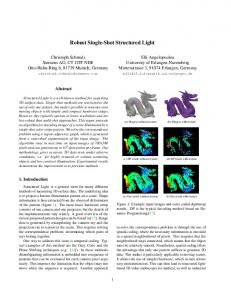
From now, it is assumed that the geometrical behaviour of the sensor is affine. In addition, let us suppose that the light pattern is an orthogonal grid (which does not represent a loss of generality: the same constraints can be generated with any pattern). Projecting a square onto a planar surface, the more generic quadrilateral formed onto the surface is a parallelogram whether an affine model is assumed. Furthermore, a parallelogram captured by an affine camera forms a parallelogram onto the retina. Hence, a parallelogram within the image corresponds to the image of a parallelogram on a 3-D plane. Relative positioning of the four points A, B, C and D in space (Figure 2a) is such as: AB = CD , AC = BD (AB ) // (CD ), (AC ) // (BD )
(17) (18)
It leads to a redundant set of constraints on W. As projective geometry keep unchanged alignment and coplanarity, equations (17) and (18) determine the same configuration of points. It has to be said that, likewise, a parallelogram completely determines a 3-D plane. Therefore, for each plane composing the scene, a unique set of parallelogram constraints is sufficient. The projection of a line produces a light plane in space. The projection of two orthogonal lines (AB) and (AC) produces two orthogonal light planes (Figure 2c). When light planes intersect planar surfaces, they produce light stripes on them whose will be imaged by the camera. We have thus two lines (A’B’) and (A’C’) in space, which belong to orthogonal planes. Since A' and B' belong to the same horizontal plane and A' and C' belong to the same vertical plane, whether the world co-ordinate system is fixed at the projector, it is obtained:
(
x A' = x B '
)(
;
y A' = y C '
(19)
)
A ' B ' ⋅ A ' C ' = x A ' − x B ' x A ' − xC ' +
(y A
'
)(
)
− y B ' y A' − yC ' +
(z A
'
)(
) (
(20)
)(
− z B ' z A' − zC ' = z A' − z B ' z A ' − zC '
)
Thus:
(A' B' )⊥(A' C' ) ⇔ z A'
= z B' or z A' = z C'
(21)
If the conditions imposed by (21) are satisfied, we obtain an orthogonality constraint, otherwise we obtain the following reduced orthogonality constraint:
(xA' − xB' )(xA' − xC' ) +(yA' − yB' )(yA' − yC' ) = 0
(22)
Each projected horizontal or vertical line of the pattern generates a light plane in space, which can be considered as a horizontal or vertical 3-D plane in the projector co-ordinate system, respectively (Figure 2b). Indeed, what it is imaged by the camera are the intersections of light planes with the surfaces composing the scene, therefore points belonging to horizontal and/or vertical planes. If a point P belongs to the horizontal plane of the Euclidean frame in which the scene will be reconstructed, then yA = 0.
Likewise, the homologue constraint xA = 0 can be expressed. Besides, two points belonging to the same plane have a component in common, which provides a constraint between the co-ordinates of both points. Furthermore, an arbitrary distance can be set between two successive horizontal planes or vertical planes. Finally, the cross-point (which appears in the image as the intersection of two light stripes) of the planes y = 0 and x = 0 can be defined as the origin of the Euclidean frame by equalling its three components to zero.
Figure 2. Euclidean Constraints
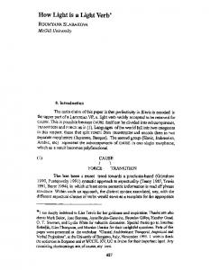
4 Experimental Results We have reconstructed 70 points of a real scene, which represents a cube (see Figure 3a). We have performed the Euclidean reconstruction using the constraints defined in the previous section. The projective reconstruction method performed here is the one proposed by Mohr et al. [8]. To illustrate the accuracy of the method, a comparison between hard-calibrated and uncalibrated reconstruction is presented on Figure 3d. As we did not have real 3-D co-ordinates but only 3-D co-ordinates computed by hard-calibration, a quantitative evaluation of the reconstruction method is not possible. However, the comparison with results obtained by hard-calibration shows that uncalibrated reconstruction from grid coding obtains good results (in a qualitative way). On Figure 4, we present results of Euclidean reconstruction performed from an image grabbed under realistic condition. Only the highlighted lines have been reconstructed. It can be noted that parallelism and orthogonality are well-recovered and relative distances are respected. The Levenberg-Marquardt algorithm is used to perform the reconstruction, only a few iterations are necessary to perform a Euclidean reconstruction from a projective one.
80
z
60 40 20 0 0 -50
-50 -100
-100
-150 -150
y
-200
x
(b) First Euclidean view
(a) Gray-level image -20
-40
80 60
-60
z 40
y
-80 20
-100
0 0
-120
-50
-50 -100
-100
-140 -180
-160
-140
-120 x
-100
-80
-150
y
-60
-150 -200
x
(d) Comparison with hardcalibration (circles)
(c) Second Euclidean view
Figure 3. Euclidean Reconstruction by geometrical constraints
90 80 70 60 50 y 40 30 20 10 0 0
(a) Structured light image
20
40
60 x
80
100
120
(b) First Euclidean view 70
80 60
60 50
z 40 40 z
20
30
0 100
20
150 50 y
100
10
100 50 0 0
50 y 0
x
(c) Second Euclidean view
0 0
20
40
60 x
80
100
120
(d) Third Euclidean view
Figure 4. Euclidean Reconstruction by geometrical constraints
5 Conclusions This paper first presents a synthetical survey on self-calibration methods. Then, after having studied the geometry of a structured light sensor, constraints which prevent the use of certain stereovision methods are listed and a method, based on the stratification of the geometries, is proposed to self-calibrate a structured light sensor. The method of Euclidean constraints is used and it is shown how geometrical knowledge of the scene as parallelism or orthogonality can be retrieved by projecting a known light pattern onto the scene. The main advantage provided by structured lighting is that the constraints are partly independent from the scene. Moreover, structured lighting permits to ensure there is known scene structure which can be used to upgrade the reconstruction to Euclidean and provides numerous constraints. Furthermore, as no constraints are required on projection matrices, the presented approach allows us to reconstruct changing the focus, the aperture and the zoom of both the camera and the projector. Therefore, the sensor can be involved in visual tasks which require self-adaptability with numerous applications as autonomous navigation, visual exploration, among others.
6 References [1] J. Batlle, E. Mouaddib, J. Salvi, "Recent Progress in Coded Structured Light as a Technique to Solve the Correspondance Problem: A Survey", Pattern Recognition, vol. 31, n°7, pp. 963-982, 1998. [2] B. Boufama, R. Mohr, and F. Veillon, "Euclidean Constraints for Uncalibrated Reconstruction", Proceedings of the 4th International Conference on Computer Vision, Berlin (Germany), pp. 466-470, May 1993. [3] O. D. Faugeras, Q.-T. Luong, S. J. Maybank, "Camera Self-Calibration: Theory and Experiments", European Conference on Computer Vision, Lecture notes on computer science, vol. 588, pp. 321-334, 1992. [4] O.D. Faugeras, "What Can be Seen in Three Dimensions with an Uncalibrated Stereo Rig?", European Conference on Computer Vision, Lecture notes on computer science, vol. 588, pp. 563-578, 1992. [5] R.I. Hartley, "Euclidean Reconstruction from Uncalibrated Views", Proceedings of the 2nd EuropeanUS Workshop on Invariance, Azores (Portugal), pp. 187-202, 1993. [6] Q.-T. Luong, T. Viéville, "Canonical Representation for the Geometries of Multiple Projective Views", Computer Vision and Image Understanding, vol. 64, n°2, pp. 193-229, 1996. [7] R.I. Hartley, "Kruppa's Equations Derived from the Fundamental Matrix", IEEE Transactions on Pattern Analysis and Machine Intelligence, vol. 19, n°2, pp. 133-135, 1997. [8] R. Mohr, B. Boufama, P. Brand, "Accurate Projective Reconstruction", Proceeding of the DarpaEsprit Workshop on Applications of Invariants in Computer Vision, Azores (Portugal), pp. 203-227, 1993.