HPE Synergy has both direct attach (DAS) and storage area network (SAN) storage options supporting SQL ..... software, a
HPE Reference Architecture for Microsoft SQL Server 2016 on HPE Synergy
Technical white paper
Technical white paper
Contents Executive summary ................................................................................................................................................................................................................................................................................................................................ 3 Introduction ...................................................................................................................................................................................................................................................................................................................................................3 Solution overview ..................................................................................................................................................................................................................................................................................................................................... 5 Design principles ...................................................................................................................................................................................................................................................................................................................................... 5 Solution components............................................................................................................................................................................................................................................................................................................................6 Hardware...................................................................................................................................................................................................................................................................................................................................................7 Sizing......................................................................................................................................................................................................................................................................................................................................................... 12 Software ................................................................................................................................................................................................................................................................................................................................................. 13 Best practices and configuration guidance for the solution ......................................................................................................................................................................................................................... 15 General configurations ............................................................................................................................................................................................................................................................................................................. 16 Transactional workload configuration ........................................................................................................................................................................................................................................................................ 16 Data Warehouse workload configuration ................................................................................................................................................................................................................................................................17 Capacity and sizing ............................................................................................................................................................................................................................................................................................................................ 26 Transactional workload ............................................................................................................................................................................................................................................................................................................ 26 Data Warehousing workload ............................................................................................................................................................................................................................................................................................... 28 Mixed workload testing ............................................................................................................................................................................................................................................................................................................ 30 Analysis and recommendations.............................................................................................................................................................................................................................................................................................. 30 Summary ...................................................................................................................................................................................................................................................................................................................................................... 31 Implementing a proof-of-concept .................................................................................................................................................................................................................................................................................. 31 Appendix A: Bill of materials ...................................................................................................................................................................................................................................................................................................... 32 Appendix B: Storage provisioning ........................................................................................................................................................................................................................................................................................ 33 Appendix C: Configuration settings .................................................................................................................................................................................................................................................................................... 39 Resources and additional links ................................................................................................................................................................................................................................................................................................ 40
Technical white paper
Page 3
Executive summary IT organizations are looking for robust infrastructure which is flexible, cost efficient, scalable, and provides a stable platform for mixed workloads without compromising on performance and the IT organization's ability to meet required SLAs to its users. HPE Synergy is architected from the ground up for composable infrastructure. The performance, flexibility, and manageability HPE Synergy provides helps businesses provision efficiently, and scale on-premises cloud Infrastructure resources quickly, reducing costs associated with stranded resources. This HPE Reference Architecture focuses on Microsoft® SQL Server 2016 database deployments on HPE Synergy platforms evaluating both Transactional and Data Warehouse (DW) workloads demonstrating sample deployment topologies and associated scaling factors. Performance – Test results show HPE Synergy’s ability to serve heavy Transactional and DW workloads. With four-socket compute modules, Transactional workloads achieved close to 50K operations per second and DW workloads achieved a sustained throughput of 6.5 GB/sec. In addition to providing individual database performance, the HPE Synergy system was able to sustain the same level of performance when all the workloads where run concurrently without any performance degradation. Scalability – The balance of compute, storage and network components in HPE Synergy are key to predictable linear scaling and unabated performance under consolidated load. Test results show near linear database growth scaling when growing from two- to four-socket compute modules and adding additional SSD media. Flexibility – The range of compute, storage and network options available with HPE Synergy provides varied high availability (HA) topology options for Microsoft SQL Server. HPE Synergy has both direct attach (DAS) and storage area network (SAN) storage options supporting SQL Server Failover Clusters and Always On Availability Groups. Manageability – The HPE OneView management suite provides an operational interface that allows system administrators to configure, update and provision both DAS and SAN storage from a single tool greatly streamlining the database provisioning process. Availability of ReST APIs can further automate frequent database deployments. Target audience: CIOs, IT architects, IT managers, database engineers and administrators. A working knowledge of server architecture, networking architecture, and storage design is recommended. Document purpose: The purpose of this document is to describe a Reference Architecture that organizations can utilize to plan for their deployment of OLTP and Data Warehouse Microsoft SQL Server 2016 workloads on HPE Synergy platform. This Reference Architecture (RA) describes testing completed in October 2016.
Introduction HPE Synergy, as a platform for Microsoft SQL Server, is an excellent solution for environments that require consistency and flexibility of resources to support a variety of different SQL Server workload scenarios. In this paper, three SQL Server 2016 systems have been provisioned using an HPE Synergy 12000 Frame (Synergy 12000) to showcase the flexibility of the composable architecture of the HPE Synergy platform for running both Transactional and Data Warehouse workloads. Using a workload simulating a financial trading platform, performance testing and characterization was conducted on a two-socket HPE Synergy 480 Gen9 (SY480) Compute Module, along with a four-socket HPE Synergy 660 Gen9 (SY660) Compute Module for high performance transactional workloads. Both of these compute modules were mapped to databases residing on a local HPE Synergy D3940 (D3940) Storage Module. In addition, a Data Warehouse workload featuring the HPE Synergy 660 Gen9 and an HPE 3PAR StoreServ 8450 (3PAR 8450) array, which serviced ad-hoc queries generated by single and multiple concurrent users, was also configured and tested.
Technical white paper
Page 4
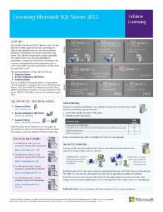
The nature of the performance characterization was to deploy, configure, tune, and capture performance metrics relevant to the testing of these workloads and items for regular task-based maintenance. Workloads were run in isolation of each other, tuned, and measured; and then also run concurrently with each other. This perspective gives us an understanding of each individual workload’s performance, scale, and resource requirement, and then demonstrates that performance is not impacted when running multiple workloads on the HPE Synergy platform. An overview of the hardware components used in this solution is shown below.
Figure 1. Solution hardware overview
Database management systems are typically one of the more over-provisioned systems in the IT Enterprise. Factors of scale for compute, memory, and storage are generally allocated with a specific forecast or life span in mind. These resources are also generally more expensive in both capital as well as operational costs. HPE Synergy, and its composability allows resource pools to be allocated, provisioned, and incrementally expanded. The entire process can be automated via HPE OneView’s RESTful API for the demands of today, and ready to be reused, to meet the needs of tomorrow.
Technical white paper
Page 5
Solution overview The HPE Synergy 12000 Frame, that was used with this test case, featured three HPE Synergy compute modules, one HPE D3940 Storage Module, along with a redundant pair of HPE Synergy 12Gb SAS Connection Modules, to provide powerful and redundant connectivity to the D3940 Storage Module, and a redundant pair of HPE Synergy Virtual Connect SE 40Gb F8 Modules, for high-speed network connectivity to multiple networks. The test case scenarios were designed to focus on three different Microsoft SQL Server 2016 workloads: two Transactional workloads and one Data Warehouse workload. The two transactional systems were built to showcase an identical workload, where compute, memory, and storage are driven by a controlled test of transactions executed from a series of test client services. All transactions that were executed against the test databases, were from TCP/IP connected clients, on an external network. The Data Warehouse system, had a much different set of resource requirements. For Data Warehouse, the solution is more focused on the throughput performance of the solution as we typically run a readintensive workload that extracts information from the database. High throughput allows us to extract and process information faster from the database. High-end computing resources are needed along with high performance storage to optimize throughput performance. The test configurations for each workload are detailed below. Small Transactional workload – The small Transactional workload featured an SY480 Compute Module, which is a two-socket system that was configured with 640GB of RAM connected to a D3940 Storage Module which is shared with the large Transactional workload. The D3940 Storage Module was fully populated with forty, 400GB 12Gb/s SAS Write Intensive Solid State drives. The storage was provisioned through HPE OneView for Synergy, as it is a managed resource. Both transactional compute modules were presented with a proportional numbers of drives, created as high-performance Advanced Data Mirroring (ADM) RAID arrays. The workload client drivers, were evenly distributed in connections for each database. For this workload, four 100GB databases were used for testing. Large Transactional workload – The four-socket Synergy 660 Gen9 Compute Module configured with 1.2 Terabytes of RAM was used for the large Transactional workload. The large workload shared the D3940 Storage Module with the small workload. However, for the large workload, a total of eight 100GB databases were used for testing. Data Warehouse workload – A Synergy 660 Gen9 with 768GB of RAM was chosen for this workload. For storage performance, the compute module was coupled with an HPE 3PAR 8450 all-flash array. This all-flash design provides tremendous amounts of throughput capability and scalability. The 3PAR 8450 is a great match for the Synergy 12000 Frame as it has the capability for storage and controller node expansion, as well as 10GbE and Fibre Channel connectivity options. While both the Synergy frame and the 8450 array have pure Fibre Channel capability, we decided to showcase the flexibility of this solution by configuring an FCoE link from the compute module to the HPE FlexFabric 5930 switch, then used pure Fibre Channel to the 3PAR 8450 array. FCoE provides high-performance network connectivity between systems and storage with both Fibre Channel and/or 10Gb Ethernet capability. This configuration was tested using a 3TB data warehouse and a mix of compute and I/O intensive queries. The Transactional workloads were tested with consistent SQL Server options and configurations, such as data and log file placement, startup flags, and memory percentage allocated to SQL Server. Maintenance tasks, such as transaction log and full backups, were also tested during the transactional load in order to observe the effects. The systems were all individually tested, to characterize essentially isolated performance of that specific workload. The tests were then executed concurrently, with all three workloads running in a combined manor. The expectation and the resulting data support that there was not an appreciable difference when the combined workloads were executing.
Design principles The systems tested were designed from the perspective that organizations typically have more than one flavor of database systems. Both Transactional and Data Warehouse systems are widely used and typically deployed in most customer environments. In many cases, organizations may have test, pre-production or staging systems for their transactional workloads that are matched to their production systems. These environments can be implemented identically to their production counterparts in function, but not fully provisioned for performance. With that in mind, the transactional systems in addition were designed to illustrate a “scale up” model. Configured and tested to demonstrate the performance gain when scaling, from the SY480 to the SY660. With the SY660 having twice the physical compute, memory, and local storage capacity of the SY480, it was expected that it would be able to deliver twice the volume of transactions (or SQL batch requests/sec) as the SY480.
Technical white paper
Page 6
The Data Warehouse and Transaction Processing workload systems were designed to demonstrate various storage and workload options. Leveraging both local and 3PAR storage, these configurations offer up the visibility into a different workload style. This solution was selected with the recognition that some organizations may have traditional workloads that have already been built on established systems. Joining these particular workloads, may help organizations decide on methods for migration to a fully integrated platform, or some variation of a legacy integrated system. These solutions are targeted at small to large enterprise customers, which need the diversity of storage, network and compute resources that can be quickly and easily managed and deployed together. This solution as a whole (both Transactional and Data Warehouse), is designed to show that these different workloads can be deployed and run concurrently within the same Synergy frame. One way to think of this solution is that it is a hybrid solution in that the Transactional solution is contained within the frame, while the Data Warehouse solution relies on external connectivity to traditional storage and storage area networks. High availability, aside from the redundancies that are present within the Synergy frame and within the capability of the 3PAR storage solution, was not tested for this design. These capabilities are present within the Synergy frame for usage by native SQL Server technologies such as “Always On”, etc., while additional capabilities are also present in the 3PAR 8450 both at the hardware level, and through additional software features such as “Remote Copy”, etc.
Solution components The components and configuration for both the Transactional and Data Warehouse designs were specifically engineered for each of these workloads. The overall solution is based on the HPE Synergy 12000 Frame along with networking components that connect to an external storage array (for the Data Warehouse workload). The HPE Synergy 12000 Frame is a base infrastructure that ties together compute, storage, network fabric, and power into a scalable solution that easily addresses and scales with various customer workloads and infrastructures. The Synergy 12000 reduces complexity in the IT infrastructure by unifying all these resources into a common bus, and with the myriad of available network and storage interconnects, allows the frame to interoperate with any other IT environment. At a high level the Synergy frame supports the following: • 12 half-height or 6 full-height compute modules. The Synergy design additionally allows for the inclusion of double-wide modules as well such as the D3940 Storage Module. • Ten fans and a single Frame Link Module for in-band and out-of-band management • Up to six 2650 watt power supplies • Up to six interconnect modules for full redundancy of three fabrics The Synergy 12000 features a fully automated and managed composer module using HPE OneView, contained within the HPE Synergy Composer module. OneView handles all the setup, provisioning, and management both at the physical and logical level. The storage for the Transactional workload features the self-contained, double-width, half-height D3940 Storage Module. The D3940 houses up to 40 Small Form Factor (SFF) 12G drives, supporting up to 153TB of raw storage capacity. This storage module provides the storage capacity and flexibility to support both our Transactional workloads concurrently.
Technical white paper
Page 7
To showcase some of the different storage network options available to the Synergy frame, the Data Warehouse workload featured the HPE 3PAR StoreServ 8450 storage array. The 8450 is an all-flash version of the 8400 array, featuring up to four controller nodes, each with a 10-core 2.4GHz CPU. The 8450 supports up to 480 SSDs with a max raw capacity of 1.8 Petabytes and easily supports demanding transactional workloads as its throughput capability easily scales as demand increases. The 8450 for this Reference Architecture, is connected to the Synergy 12000 through an HPE FlexFabric 5930 switch featuring Fibre Channel and 10Gb Ethernet ports. Figure 2 below provides an overview of the frame and the storage area network connecting the 8450 array.
Figure 2. Solution hardware overview
Hardware Frame and fabric HPE Synergy architecture is designed to optimize management of scale, reducing complexities that are generally present with expanding and deploying across enclosures or racks. HPE Synergy Composer, powered by HPE OneView, allows management of up to 21 frames of hardware via Fame Link Modules. In this paper, we built all of the resources within the context of one HPE Synergy 12000 Frame with one Synergy Composer. This would be representative of a small base deployment, proof of concept, or QA environment. The flexibility of the Synergy 12000 allows the expansion and unification of multiple frames under a single management umbrella. The interconnects in the Synergy 12000 allow internal and external storage devices, storage networks and local area networks to connect and interact with the frame. For our solution, we required a SAS interconnect for compute modules to connect to the internal D3940 Storage Module, and an Ethernet module to connect to the 5930 switch (and on to the 3PAR 8450) for our FCoE storage network. In order to provide failover redundancy and performance aggregation, we deployed two modules for each type needed.
Technical white paper
Page 8
Frame interconnect modules
Table 1. Interconnect modules installed Interconnect Bay
IC module
Mapping
Required for workload
Interconnect bay 1
Synergy 12Gb SAS Connection Module
Mezzanine Slot 1, and Slot 4 (SY660 only)
Transactional
Interconnect bay 3
Synergy VC SE 40Gb F8 Connection Module
Mezzanine Slot 3, and Slot 6 (SY660 only)
Transactional and Data Warehouse
Interconnect bay 4
Synergy 12Gb SAS Connection Module
Mezzanine Slot 1, and Slot 4 (SY660 only)
Transactional
Interconnect bay 6
Synergy VC SE 40Gb F8 Connection Module
Mezzanine Slot 3, and Slot 6 (SY660 only)
Transactional and Data Warehouse
Each of the interconnects maps to specific mezzanine ports on the compute modules. The Synergy 480 Compute Module features three slots, while the SY660 Compute Module has six slots. Each 12Gb SAS module supports up to 72GB/sec, more than enough than required for our D3940 Storage Module, so the 12Gb SAS modules were deployed in pairs for redundancy only. Although each 40Gb F8 connection module also provided enough total bandwidth for our solution, we could only map a single interconnect to two mezzanine ports. Deploying an additional F8 module allowed us to aggregate bandwidth on the SY660 Compute Module by giving us the ability to map the two interconnects to a total of four different mezzanine ports on two Ethernet cards in the SY660 Compute Module. By mapping to four 20Gb ports on two HPE 3820C 20Gb/s Ethernet mezzanine adapters, we had a total of 80Gb/s of aggregate bandwidth. In our single interconnect testing, we were limited to two ports on one mezzanine card for a total of 40Gb/s. Compute modules Four different compute modules are available for the Synergy frame: • Synergy 480 Gen9 – The SY480 is a general-purpose, single-width, half-height, two-socket module supporting a wide range of applications and deployments. • Synergy 620 Gen9 – The SY620 is a mission-critical, single-width, full-height, two-socket module featuring extra CPU, memory, and storage capacity versus the SY480, along with additional redundancy for all mission-critical deployments. • Synergy 660 Gen9 – The SY660 is a general-purpose, single-width, full-height, four-socket module supporting a wide range of applications and deployments. • Synergy 680 Gen9 – The SY680 is a mission-critical, double-width, full-height, four-socket module featuring extra CPU, memory, and storage capacity versus the SY660, along with additional redundancy for all mission-critical deployments. For our testing we chose the two general purpose modules, the Synergy 480 two-socket module, and the Synergy 660 four-socket module. While these modules have slightly less capabilities and availability features than the mission-critical modules, they provide a solid foundation for deploying many different types of workloads for SQL Server. Shown below are the hardware details of our deployed compute modules. Tables 2 and 3 below depict the compute module configurations for the Transactional testing. Table 2. Compute node configuration transactional SY480 Model
HPE Synergy 480 Gen9
Processors
2 processors, Intel® Xeon® CPU E5-2683 v4 (2.1 GHz / 16-core)
Memory
640GB DDR4-2400 LRDIMM
Local drives
(2) 300GB 10K 6G HDD (OS)
Local storage controller
(1) HPE Smart Array P240nr/1GB FBWC 12Gb 1-port Internal SAS Controller (OS & SQL Server Installation)
Mezzanine cards
(1) HPE Smart Array P542D Controller (1) HPE Synergy 3820C 10/20Gb Converged Network Adapter
Technical white paper
Page 9
Table 3. Compute node configuration transactional SY660 Model
HPE Synergy 660 Gen9
Processors
4 processors, Intel Xeon CPU E5-4660 v4 (2.2 GHz / 16-core)
Memory
1280GB DDR4-2400 LRDIMM
Local drives
(2) 300GB 10K 6G HDD (OS)
Local storage controller
(1) HPE Smart Array P240nr/1GB FBWC 12Gb 1-port Internal SAS Controller (OS & SQL Server Installation)
Mezzanine cards
(1) HPE Smart Array P542D Controller (1) HPE Synergy 3820C 10/20Gb Converged Network Adapter
Table 4 below depicts the compute module configuration for the Data Warehouse testing. Table 4. Compute node configuration (Data Warehouse SY660) Model
HPE Synergy 660 Gen9
Processors
4 processors, Intel Xeon CPU E5-4660 v4 (2.2GHz, 16 core, 40M cache)
Memory
768GB DDR4-2400 RDIMM
Local drives
(2) 300GB 10K 6G HDD (OS)
Local storage controller
(1) HPE Smart Array P240nr/1GB FBWC 12Gb 1-port Internal SAS Controller (OS & SQL Server Installation)
Mezzanine cards
(1) HPE Synergy 3820C 10/20 Converged Network Adapter (Dual FCoE) Or (2) HPE Synergy 3820C 10/20 Converged Network Adapter (Quad FCoE)
Note For this Data Warehouse workload, we utilized a 3TB test database. The largest table in this database is approximately 800GB, so our memory sizing for the Data Warehouse compute node is scaled accordingly so that the system can fit this table into memory. Mezzanine interfaces The mezzanine ports supported by the Synergy compute modules allow for the logical mapping to the interconnect modules in the back of the Synergy 12000 Frame. The two-socket Synergy 480 Compute Module has three slots, while the four-socket SY660 Compute Module has a total of six slots. Table 5 below depicts the mezzanine mappings for our solutions: Table 5. Mezzanine cards and interconnect mappings Mezzanine slot
Synergy 480 Gen9
Synergy 660 Gen9 (Transactional)
1
Smart Array P542D (Maps to IC 1, 4)
Smart Array P542D (Maps to IC 1, 4)
2
X
X
3
Synergy 3820C 10/20Gb (Maps to IC 3, 6)
Synergy 3820C 10/20Gb (Maps to IC 3, 6)
4
N/A
X
5
N/A
X
6
N/A
X
Synergy 660 Gen9 (Data Warehouse)
Synergy 3820C 10/20Gb (Maps to IC 3, 6)
Synergy 3820C 10/20Gb (Maps to IC 3, 6)
Technical white paper
Page 10
Each mezzanine card has two ports which, when deployed with two interconnects, map to one port on each of the interconnects. Additionally, ports on the 3820C cards have logical sub-ports that can be mapped to additional VLANs. In our case, we carved out 1Gb of bandwidth to our management network. With the two mezzanine cards installed into the Synergy 660 for the Data Warehouse workload, we were able to map a total of four ports (20Gb/sec each) to the two interconnects, giving us a total of up to 80Gb/sec of bandwidth from the SY660 Compute Module to the 5930 switch. D3940 storage The Synergy D3940 Storage Module is a 40 SFF half-height, double-width storage module for use in the Synergy frame. The D3940 supports both 6G and 12G disk drives and SSDs. Up to five storage modules can be deployed within a single Synergy 12000 Frame, providing up to 200 total drives. With a high performance SAS connection and I/O adapter, the D3940 provides sixteen 12Gb/s SAS lanes back to the interconnect modules. An additional I/O adapter can be deployed for redundancy within the module. The D3940 was chosen for this solution as it has the flexibility to be shared between multiple compute modules and the performance to drive concurrent workloads throughout the frame. The D3940 is accessed by the compute modules through the use of Synergy 12G SAS interconnect modules in the frame, and P542D mezzanine cards in the compute modules. Logical connections are set up in HPE OneView to connect the ports in the mezzanine cards to the ports in the SAS interconnect modules. Figure 3 below details the physical and logical connections to the D3940 Storage Module.
Figure 3. Logical SAS connections
Technical white paper
Page 11
HPE 3PAR StoreServ 8450 The HPE 3PAR StoreServ 8450 all-flash array used in the Data Warehouse workload testing, was chosen for its ability to easily connect to the Synergy frame through Fibre Channel, or Fibre Channel over Ethernet (FCoE), and for the flexibility of configuration options, performance, and scale throughout the small, medium and large enterprise arena. The HPE 3PAR 8450 utilized for the Data Warehouse workload features four controllers and 64 480GB SSD drives. For connectivity to the Synergy frame, eight 8Gb Fibre Channel connections are run to the HPE 5930 FlexFabric switch. The 8450 is adaptable to changing workloads and can scale up simply by adding drive shelves and drives. Figure 4 below depicts the configured 3PAR 8450.
Figure 4. 3PAR array for Data Warehouse
Technical white paper
Page 12
Sizing Sizing for the 8450 array was done through the HPE NinjaSTARS sizing tool. This sizing tool is ideal for modeling different configurations of single or tiered storage arrays, and the likely types of workloads that will be running on them. Since the 8450 array is all flash, we concentrated on SSD sizing only. Since our workload is a sequential scan focused data warehouse featuring both RAID5 for database, and RAID1 for logs, etc., we ran the tool with both a RAID5 and RAID1 configuration, and averaged the two to get an approximate storage capacity for our 3TB database solution. Figure 5 below depicts the output of the tool.
Note NinjaSTARS (STorage Assessment, Recommendation, and Sizing) is an HPE 3PAR sizing tool used by account teams to size storage solutions. If you are sizing an HPE 3PAR array, contact your local account team for more information about NinjaSTARS.
Figure 5. NinjaSTARS sizing session output RAID 1
Technical white paper
Page 13
The RAID1 solution came in at a total of 12TB of usable capacity, and estimated performance throughput of 12GB/sec. The RAID5 solution featured the same throughput, but with a usable capacity of 21TB as shown in figure 6.
Figure 6. NinjaSTARS sizing session output RAID 5
So with a mix of both RAID1 and RAID5, our solution has an estimated usable capacity of 17TB. Between the main database, TempDB, and the associated log files, our solution requires a minimum of about 5TB. The SSD drives would be at about 30-40% capacity to start, giving the solution the capability to grow about an additional 100% as growth needs dictate.
Software The software components for this solution consist of the operating system running on the compute modules, the Database management software, and the Management software. No other software packages are utilized. Details of these software components are contained in this section. Management software The solutions presented here are fully provisioned and managed through the use of the HPE OneView software residing on the Synergy Composer. The Synergy Composer, powered by OneView, reduces management complexity with the ability to manage multiple Synergy frames from one console. The composer extends management capabilities with several key features related to the composable infrastructure: • Fully programmable interface with a unified API • High Availability capability • Control and monitoring of resources – Auto Discovery of all frame resources – Auto Integration of new resources – Templates, with the ability to create logical mappings within the frame – Zoning capability for up to 200 storage devices per frame – Management across multiple subnets – Scaling multiple frames – Automatic/staged driver/firmware/OS updates
Technical white paper
Page 14
Figure 7 below details the categories of resources that are managed within OneView.
Figure 7. OneView resources
Firmware and driver updates HPE Synergy using OneView, has the capability to automatically stage and deploy firmware and driver updates throughout the entire infrastructure using online staged updates
Figure 8. Driver/Firmware updates
The configurations for these updates are stored on the Synergy Composer, and can be edited, assigned, and deployed independently of any server hardware in the frame. Server profiles Server profiles define how the Synergy infrastructure is configured and managed. The built-in software intelligence automates the process without human intervention, significantly reducing management and operational cost. Server profiles are a powerful way to use templates to deploy a one-to-many model where a single common profile can be created and deployed to multiple servers in an automated fashion. Server profiles contain settings such as: • Firmware levels • BIOS settings • Boot order • Network connections • Shared Storage connections
Technical white paper
Page 15
For the solutions presented here, the server profiles dictated which network each compute module was assigned to, storage mappings, and driver and firmware updates. For this solution, extensive configuration in the “Connections” portion of the server profiles was needed to map the various network and storage resources both within and external to the frame. As an example, the server profile for the Synergy 660 Gen9 utilized for the Data Warehouse workload consisted of a total of five network connection mappings. These logical/physical mappings created network adapters in the operating system that mapped mezzanine ports in the compute module to network ports in the Synergy interconnects. Figure 9 below shows the connections screen for the Data Warehouse compute module.
Figure 9. Connections screen
This depicts the Quad FCoE configuration for Data Warehouse in which four separate 20Gb/s FCoE network connections were deployed. In addition, the Network_210 connection was used for management access to the server using tools such as Remote Desktop. Application software The following application and operating system software was used for the tested systems: • Microsoft Windows Server® 2016 Enterprise Edition (x64) • Microsoft SQL Server 2016 Enterprise Edition (x64)
Best practices and configuration guidance for the solution The following workload configurations outline the hardware and software configurations leveraged to deploy the SQL Server topology on HPE Synergy. Most of these settings were centered around some of the operating system and BIOS settings that were used on the servers during our testing. The SQL Server specific settings can be found within the Workload specific settings. The settings in the “General configuration” section are common across both the Transaction and Data Warehouse based workloads.
Technical white paper
Page 16
General configurations BIOS settings The following compute module BIOS settings were changed from their defaults for this solution. These settings provided the best performance for the various workloads tested. Table 6. BIOS settings Parameter
Setting
Description
Workload
Power Regulator Setting
Static High Performance Mode
Ensures that System is running at full power during all times
Both
QPI Snoop Configuration
Clustered on Die
Provides increased memory bandwidth for highly optimized NUMA configs
Transaction only
Operating system settings For Windows Server 2016, the Power plan was set to “High Performance” in the Power portion of the Control panel. This ensured that the system was operating at full power during all phases of the testing.
Figure 10. OS power setting
Transactional workload configuration The transactional configuration focused mainly on the configuration of the hardware and OS, and the storage setup. Detailed below is some of the test work that was completed to determine the best configuration for transactional. Synergy D3940 configuration Storage in the D3940 Storage Module can be presented to the compute modules in numerous ways. For our transactional workload characterization, we chose to present the storage as raw JBOD. Each D3940 can contain up to 40 SFF drives. These drives needed to be distributed proportionally to each workload requirement of the SY480 and SY660 Compute Modules. RAID 10 with Advanced Data Mirroring (ADM) was chosen for data volumes due to a 26.3% higher random write IOPS over non-ADM RAID10 volumes. Sequential 64K writes where appropriate using non-ADM RAID 10 volumes. RAID10 ADM provides greater fault tolerance by copying the data onto two mirrored drives instead of one. Therefore each “primary” drive functions as a “trio”. The drawback to using Advanced Data Mirroring is the expense associated with buying additional drives. The effective capacity of a RAID10 ADM set is one-third of the total drive capacity. Table 7 shows the drive distribution and LUN characteristics that were used for the transactional database layout on the D3940 Storage Module. Table 7. Storage layout for Transactional database layout System
LUN purpose
SSD quantity
RAID type
Capacity
SY480
Data
12
RAID10 with ADM
1.8TB
SY480
Logs
4
RAID10
800GB
SY660
Data
18
RAID10 with ADM
2.4TB
SY660
Logs
6
RAID10
1.2TB
Technical white paper
Page 17
Compute module configuration The following table lists the transactional database distribution among the compute modules. It is recommended that the database-to-memory ratio be kept to a ratio of 2:1 or lower to ensure minimum physical reads. In other words, ensuring that data and index size did not exceed double the buffer pool size (SQL Server MAXMEMORY setting). A setting of 1:1 was used to optimize performance. Table 8. SQL memory settings, Transactional database distribution System
Database size
Database quantity
MAXMEMORY
Ratio
SY480
100GB
4
400GB
1:1
SY660
100GB
8
800GB
1:1
The compute module BIOS settings where configured as follows: • QPI Snoop set to Clustered on Die • Hyper-Threading enabled (default) • NUMA group size set to Clustered The Windows Server 2016 operating system and SQL Server 2016 binaries were installed on a pair of local SSDs on each compute module. The drive pair was configured as a RAID1 array and formatted as two volumes. SQL Server configuration The transactional instances where configured as follows: • Startup trace flag -T834 • Lock pages in memory for SQL Server service account • Automatic softNUMA partitioning disabled
Data Warehouse workload configuration For the Data Warehouse Synergy platform a Synergy 660 Gen9 Compute Module was chosen. The SY660 features the ability to install up to four processors and 3TB of memory. In addition, with six mezzanine slots available, it has the flexibility to meet networking and storage connectivity needs. For the backend storage, an HPE 3PAR StoreServ 8450 storage array was chosen. The 3PAR 8450 is an “all flash” version of the 3PAR 8400 series. The array features up to 480 Solid State Drives (SSDs) with a current max capacity of 1.8 Petabytes. The 8450 also features up to four controller nodes for maximum throughput. For our 3TB Data Warehouse, 64 x 480GB SSDs were chosen for the 3PAR array. With only 64 drives, the SSDs provide more than enough (over 300GB/sec) throughput capability for this solution. Traditional disk drives provide higher storage capacity at the expense of throughput. The 64 SSDs provide over 30TB of raw storage, providing enough capacity to cover, database, log and TempDB files for our 3TB test database. The extra capacity allows us the flexibility to use different RAID levels for the various types of files in the Data Warehouse. Table 9. Backend storage design (Data Warehouse) Model
HPE 3PAR StoreServ 8450 array
Storage controllers
4 nodes
Drives
64 x 480GB 12G SSD
Network ports
8 x 8Gb Fibre Channel
Technical white paper
Page 18
Storage configuration For the Data Warehouse workload, the HPE 3PAR StoreServ 8450 provided the backend storage. When provisioning storage from the 3PAR array, two different storage concepts are presented: • Common Provisioning Groups (CPGs) – A CPG is essentially a pool of drives from which virtual or logical storage volumes can be allocated. CPGs also dictate which RAID level will be used when virtual storage volumes are created from this pool. CPGs can be either Thin or Thickly provisioned. With Thin provisioning, space is allocated as it is requested, where as a thick provisioning model allocates storage space when the CPG is created. • Virtual Volume (VV) – Virtual volumes are the storage LUNs that are presented to the host. When creating virtual volumes, a CPG must be specified. All data residing on the virtual volume will be spread across the drives residing in the CPG.
Figure 11. 3PAR storage hierarchy
Technical white paper
Page 19
3PAR storage design For the Data Warehouse workload testing, the following CPGs and Virtual Volumes were created. Table 10. 3PAR CPG configuration CPG
RAID type
Media
Content
Synergy_Data
5
SSD
Synergy Database Files
Synergy_TDB_Log
10
SSD
Synergy TempDB Files and Database Log Files
Table 11. 3PAR Virtual Volume layout Virtual Volumes
Provisioning type
Provisioned size
Space utilized during testing
Content
Syn_DB
Thin
12TB
5.5TB
Database Files for 3TB Data Warehouse
Synergy_Log
Thin
1TB
400GB
SQL Log Files for Data Warehouse and TempDB Databases
Synergy_TempDB
Thin
3TB
1.5TB
Database Files for TempDB
SQL Server configuration The SQL Server Database, Log and TempDB files were configured on each LUN to take advantage of the CPUs and cores available on the system as well as provide multiple files to read and write concurrently to provide the best file system performance from a SQL standpoint. The following sections detail the SQL file layout for each LUN. Database The Database LUN was configured initially with 8 x 750GB NDF files in separate filegroups to allow for future flexibility and performance across the database.
Figure 12. DB file layout
Technical white paper
Page 20
Log For the RAID10 Log LUN, 2 x 100GB files were created for capacity.
Figure 13. Log layout
TempDB To maximize TempDB capacity and performance for some of the larger sort and ordering operations, the following layout was implemented using 16 x 96GB files on the RAID10 TempDB LUN. The TempDB log files were created in the same way as the Database log files and placed on the Log LUN as well.
Figure 14. TempDB file layout
Technical white paper
Page 21
Network topology The Fibre Channel ports from the 3PAR array are connected to an HPE FlexFabric 5930 switch. This switch has the capability to provide modules for both 10/40Gb Ethernet and Fibre Channel in the same chassis. The Synergy frame is also connected to the 5930 switch using 40Gb Ethernet connections. Fibre Channel over Ethernet (FCoE) is then used to connect the Synergy 660 to the 3PAR array, using the Ethernet link to the switch, and the Fibre Channel link to the 3PAR array. Performance testing for this workload was performed using both one (Dual FCoE) and two (Quad FCoE) HPE Virtual Connect SE 40Gb F8 Interconnect modules. Two 40Gb Ethernet links were connected to each interconnect module used. These links carried the FCoE traffic from the Synergy frame to the 5930 switch, then Fibre Channel links were used to connect to the 3PAR storage array. Figure 15 below details the network connectivity for the Data Warehouse configuration utilizing one interconnect module.
Technical white paper
Page 22
Figure 15. FCoE network configuration with Dual FCoE connections (Data Warehouse)
For the Quad FCoE configuration utilizing two interconnect modules, a total of four 40Gb Ethernet connections were deployed, with two connections to each interconnect. Figure 16 below depicts the Quad FCoE configuration.
Figure 16. FCoE network configuration with Quad FCoE connections (Data Warehouse)
Technical white paper
Page 23
Each interconnect module maps to a different mezzanine port/card on the Synergy 660, so in order to utilize multiple interconnect modules simultaneously, separate FCoE networks were created, each mapping to one-half or one-fourth of the host ports on the 3PAR storage array depending on the configuration. Figure 17 below details network topology linking the 3PAR array to the Synergy 660 using Dual FCoE connections.
Figure 17. Dual FCoE network topology
For the Dual FCoE configuration, two separate Virtual Local Area Networks (VLANs) and two separate Virtual Storage Array Networks (VSANs) were created. Each of those VLAN/VSAN combinations were connected to four ports on the 3PAR 8450 storage array. In turn, the two 40Gb Ethernet connections coming in from the Synergy Ethernet interconnect in slot 3 were mapped separately to each of the VLAN/VSAN
Technical white paper
Page 24
combinations. Finally, two separate networks were created in HPE OneView for the two FCoE networks, and assigned separately to individual Synergy 3820C Ethernet mezzanine card ports in the SY660 Compute Module. With this configuration, two separate FCoE SAN fabrics are presented to the Windows Server 2016 operating system on the SY660 Compute Module. In order to utilize both 20Gb connections back to the 3PAR storage array, Windows® Multipath Input/Output (MPIO) was utilized. MPIO takes all eight of the incoming paths to the storage array and load balances them to extract the maximum storage performance. For the Quad FCoE connection depicted below in figure 18, a total of four 40Gb connections, four VLAN/VSAN combinations, and four mezzanine ports were used (across mezzanine cards in slots 3 and 6)
Figure 18. Quad FCoE network topology
Technical white paper
Page 25
Each mezzanine port on the 3820C network adapters, has the capability of creating multiple subports, each containing multiple networks. The sum of these subports cannot exceed the bandwidth of the physical mezzanine ports, which is 20Gb/s. Network connections and port assignments are all configured with HPE OneView under the “Server Profile” screen, as shown below.
Figure 19. Server connections layout (Quad FCoE)
We see in figure 19 that there are a total of five networks for the Quad FCoE connection: • VLAN 210 – This is our Local area Ethernet network for management and monitoring. This is mapped to the “A” subport of mezzanine port 3:1 • FCoE VLAN 3000 – Our first FCoE VLAN. This is mapped to a single 40Gb Ethernet link and two 3PAR storage ports. Additionally this also maps to VSAN 100 for FCoE zoning purposes. • FCoE VLAN 3001 – Our second FCoE VLAN. This is mapped to a single 40Gb Ethernet link and two 3PAR storage ports. Additionally this also maps to VSAN 200 for FCoE zoning purposes. • FCoE VLAN 3002 – Our third FCoE VLAN. This is mapped to a single 40Gb Ethernet link and two 3PAR storage ports. Additionally this also maps to VSAN 300 for FCoE zoning purposes. • FCoE VLAN 3003 – Our fourth FCoE VLAN. This is mapped to a single 40Gb Ethernet link and two 3PAR storage ports. Additionally this also maps to VSAN 400 for FCoE zoning purposes. The Dual FCoE configuration was the same with the exception that the mezzanine 6 ports were not available, so the configuration featured only VLAN 3000 and VLAN 3001, with VLAN3001 being mapped to mezzanine port 3:2-b.
Technical white paper
Page 26
Once everything is set up correctly, Windows MPIO will see all eight paths, in a state of “Active/Optimized”, which means that it will use and load balance network traffic over all eight paths.
Figure 20. Windows MPIO
Once configured, the FCoE connected drives look the same as any other drives in the Disk Management MMC, and are initialized, and formatted accordingly. Both the Dual and Quad FCoE configurations were tested to show the performance and scalability of the FCoE solution as we added an additional interconnect and mezzanine card. For throughput requirements of less than 4GB/sec, the Dual FCoE configuration can be used, while higher requirements dictate the use of the Quad configuration.
Capacity and sizing The following sections detail the results of the performance testing for the three main test scenario, transactional, Data Warehouse and mixed workloads, as described in this RA.
Transactional workload The Transactional workloads simulate a stock market trade environment. For the two-socket compute module we used 4 x 100GB databases, and for the four-socket compute module we used 8 x 100GB databases. Each of the databases were configured with NUMA affinity to one NUMA node. In other words, each NUMA node will process transactions from a single database. Transactional performance metrics In these tests each compute module was evaluated individually to assess roughly how many batch requests per second compute capability can be leveraged when the processor load reaches 80% utilization. Please note this is not a maximum, rather a stable operational data point representative of a production load scenario. In other words, this is not a benchmark nor a maximum achievable by the system. An analysis was then made using the data to compare the relative scaling to verify that the transactional capability can double as we double the processors.
Technical white paper
Page 27
Figure 21 shows the nominal IOPS and batch requests per second achieved with each compute module when running at a nominal 80% processor utilization rate. As expected, baseline testing showed that the steady state IOPS load on the server nearly doubles from 6,381 to 10,507 IOPS when comparing a two-socket compute module performance versus the four-socket compute module.
Disk Transfers/Sec 12000 10000
IOPS
8000 6000 4000 2000 0 480
660
Compute Module
Figure 21. IOPS comparison between two- and four-socket compute modules
Figure 22 shows the transactional rate (batch requests per second counter) more than doubles from 22,124 to 49,686 batch requests per second when comparing two-socket and four-socket modules.
Batch Requests Per Second 60000
Time in Seconds
50000 40000 30000 20000 10000 0 480
660
Compute Module
Figure 22. Transaction rate comparison between two- and four-socket compute modules
Technical white paper
Page 28
Figure 23 shows the transaction log throughput. It also nearly doubles, showing the storage module was able to scale with the doubling of the compute module workload.
Throughput 30
Megabytes
25 20 15 10 5 0 480
660
Compute Module
Figure 23. Log Write throughput comparison between two- and four-socket compute modules
From the data above we have demonstrated that when using NUMA affinity, workloads can efficiently scale from two to four sockets, and this gives architects confidence in compute module and overall system scalability along with proper database placement and configuration information for deployments.
Data Warehousing workload For the Data Warehousing workload running on the Synergy 660 Compute Module, data warehousing queries were run against a 3 TB data warehouse database. Twenty-two separate queries were run in both single query and multiple query modes. In single query mode, the query run times were aggregated for comparison. Initial testing featured an FCoE configuration using a single 20Gb/sec connection from the SY660 to the 40Gb Ethernet module in the Synergy frame. Later, testing was repeated using an additional 20Gb/sec link on the SY660 to the Synergy frame (and the HPE 5930 switch). Test comparisons are also listed for performance when the Data Warehouse workload is running by itself on the frame, and also when both Data Warehouse and Transactional workloads are running. Performance metrics For the Data Warehouse testing, a few different parameters were captured and measured. The definitions for these metrics are listed below: • Single Query Aggregation – For the single query testing, the query times for each of the 22 queries were recorded and added together to form a complete end to end query time. • Throughput – Throughput is an important Data Warehouse metric. It measures the amount of data that can be read and processed over a given time. This is typically expressed in MB/sec or GB/sec. Throughput was measured using our workload with 20 parallel queries running.
Technical white paper
Page 29
During the testing, metrics were gathered running with a single Ethernet interconnect (Dual FCoE, 2 x 40Gb/s connections) and then with two Ethernet interconnects (Quad FCoE, 4 x 40Gb/s). Results were compared to see the initial gains in performance as more storage networking bandwidth was added. Additionally, the Transactional workloads were executed concurrently with the Data Warehouse workload on the same Synergy frame to see if there was any performance degradation across the common Synergy backplane. These results are listed here also. Table 12. Performance results Metric
Dual FCoE
Quad FCoE
Quad FCoE with Transactional
Comment
Single query aggregation
981.99 seconds
667.74 seconds
658.37 seconds
Well within normal variance between test runs
Total throughput
4.0GB/sec
6.6GB/sec
6.6GB/sec
More than 50% increase in throughput with the Quad FCoE. No change in throughput when running with Transactional workload on the frame
With the added bandwidth of the Quad FCoE configuration, single query performance improved by about 25-30%. For some queries, the performance differences were closer to 40-50%. Figure 24 below depicts the single query aggregation for both the Dual and Quad FCoE configurations. Figure 25 depicts examples of two I/O intensive queries and the performance differences achieved by going from the Dual to Quad FCoE configuration.
Figure 24. Single query aggregation performance Dual versus Quad
Figure 25. Select single query performance
Technical white paper
Page 30
For the concurrent workload, throughput was measured using an I/O heavy mix of 20 queries running simultaneously. In both tests the SQL MAXDOP setting was set to 8, per Microsoft Recommendations for NUMA based servers with 16 cores per CPU. Various Resource governor memory settings were tried, but they provided little change from using the default Resource governor memory setting of 12%. Overall throughput increased by over 50% to a maximum of 6.6GB/sec. Table 13. Concurrent workload Metric
CPU time
Avg Disk sec/ Read (DB Disk)
Throughput
MAX DOP setting
Resource governor
Dual FCoE config
45
0.02
4GB/sec
8
RG12
Quad FCoE config
40
0.05
6.6GB/sec
8
RG12
Mixed workload testing For the concurrent workload testing, the Data Warehouse single query, multiple Data Warehouse query workload mix, and the Transactional workloads were run simultaneously on the Synergy frame. From the Data Warehouse standpoint, performance was unchanged as total concurrent query throughput remain unchanged at 6.6GB/sec. Single query aggregation performance actually improved a bit by over 9 seconds, but this would typically fall into a normal variance range between test runs. The Transactional workloads also remained unaffected during concurrent load showing the sizing and scale of the storage module performed well within the designed I/O limits leaving room for additional workloads or growth. Total workload IOPS for both transactional servers combined exceeded 21,000 IOPS and the cumulative transactional rate exceeded 67,000 IOPS and there was no discernable decrease in performance as compared to their individual compute module baselines. The aggregate bandwidth of both log volumes associated with each compute module was 600MB/s.
Analysis and recommendations Transactional workload The two-socket compute module supports one dual-port SAS card rated at 96Gb/s, while the four-socket module supports two dual-port SAS cards effectively doubling the bandwidth to 192Gb/s. The storage module supports 192Gb/s combined. Given the low bandwidth requirements for transactional systems, we don’t see a sizing concern for log file throughput under transactional loads. The SAS storage module also was able to process I/O load surges such as database checkpoint writes. We measured small I/O write spikes in excess of 100K IOPS, above the overall 20K IOPS steady stead load. Design and sizing of your deployment should include a MAX IOPS per compute module and ensure sufficient SSD drives are zoned into LUNs to accommodate the maximum plus a margin. With a benchmark of approximately 400K IOPS per frame, a single storage module can accommodate all the compute modules in the frame (assuming 10), at 40K IOPS each, well above what we needed for our test databases. RAID10 ADM is useful when higher IOPS are needed during 8K random writes such as SQL datafile checkpoint writes. In summary, the following recommendations should be followed: • Use RAID10 ADM for Data volumes for increased random write IOPS • Use regular RAID10 for Logs Data Warehouse workload Our 3PAR storage array with 64 SSDs, has a potential throughput capability well in excess of 300GB/sec, according to our calculations using 3PAR guidance. With 8 x 8Gb Fibre Channel ports on the 3PAR, our potential access to that storage is around 64Gb/s or 8GB/sec. With our two HPE 3820C dual-port 20Gb mezzanine cards, our total throughput potential to the Synergy 660, would be a maximum of 10Gb/sec. In order to provide more than 8 Gb/sec to the 3PAR array, this would require additional Fibre Channel cards on the 3PAR, and an additional Fibre Channel module on the 5930 switch. For this solution it was deemed, that the extra cost and complexity involved outweighed the slight performance gain that we might see so we decided to use eight FC connections to the 3PAR. Our target throughput goal was about 60-70% of potential throughput. So with 8GB/sec of potential throughput, our target for the Quad FCoE solution was about 5.6GB/sec and for the Dual FCoE solution with 5GB/sec of potential performance our target was 3.5GB/sec. Our peak throughput for the Quad FCoE configuration of 6.6GB/sec and the
Technical white paper
Page 31
Dual FCoE with 4GB/sec comes within 80% of that maximum figure, which are impressive results given the data path using Fibre Channel over Ethernet connections going through the Synergy backplane, through a switch, then onto the 3PAR array. In our single query testing, we saw an overall 25-30% gain in single query aggregation, while performance from some queries improved by up to over 50% when scaling form the Dual to Quad FCoE configuration. This shows that FCoE is a solid alternative to running pure Fibre Channel, from the Synergy frame all the way to the 3PAR array. Though it does incur some overhead, the penalty seems very slight. This would be a great solution for those enterprise customers looking for throughput performance in the 6GB/sec range. For those that require less performance to start, the Dual FCoE configuration can be deployed with performance in the 4GB/sec range. Mixed workload The Synergy 12000 also provides a robust frame for running multiple servers and multiple workloads concurrently without adversely affecting each other as shown by our multi-workload results. Our Data Warehouse results for both single and multiple concurrent queries show no appreciable performance change when running only the Data Warehouse workload versus running the Data Warehouse workload along with the Transactional workloads on the Synergy frame concurrently.
Summary The HPE Synergy platform provides a scalable and flexible environment for Microsoft SQL Server 2016 database environments. The choice of both direct attach SAS, SAN, or both, allows for both Failover cluster and Always On availability group high availability topologies. Backplane and storage module bandwidth provide ample capability and the compute modules are designed to accommodate additional I/O cards as they scale providing the correct and adjustable amount of resources to accommodate different or growing workloads. The HPE OneView management software simplifies the management and enables server administrators to easily adjust storage by providing a single pane of glass hardware pooling view for both direct attach and external HPE 3PAR storage arrays. When put together, the performance, scaling flexibility and ease of use result in an effective platform for database deployments in your enterprise IT environments. This paper has demonstrated the flexibility and capability of the HPE Synergy platform to deliver multiple database environments within the same frame, and allow those systems to work independently of each other, while delivering peak performance even when the frame is being accessed concurrently. Performance testing showed that the HPE Synergy 12000 platform is ideal for enterprise customers of various sizes with transactional requirements in the 50K/sec range and Data Warehouse customers with throughput requirements approaching 6.5GB/sec.
Implementing a proof-of-concept As a matter of best practice for all deployments, HPE recommends implementing a proof-of-concept using a test environment that matches as closely as possible the planned production environment. In this way, appropriate performance and scalability characterizations can be obtained. For help with a proof-of-concept, contact an HPE Services representative (hpe.com/us/en/services/consulting.html) or your HPE partner.
Technical white paper
Page 32
Appendix A: Bill of materials Note Part numbers are at time of publication and subject to change. The bill of materials does not include complete support options, cables, transceivers or other rack and power requirements. Table 14. BOM Qty
Part number
Description
Frame components 1
797738-B21
HPE Synergy 12000 Frame
1
804353-B21
HPE Synergy Composer
2
794502-B21
HPE Virtual Connect SE 40GB F8 Module for HPE Synergy
2
755985-B21
HPE Synergy 12Gb SAS Connection Module with 12 Internal Ports
1
755984-B21
HPE Synergy D3940 12Gb SAS Drive Enclosure with 40 SFF (2.5in) Drive Bays
40
802582-B21
400GB 12Gb/s SAS Write Intensive Solid State Drive
Compute modules and components Synergy 480 1
732350-B21
HPE Synergy 480 Gen9 CTO Module
1
759557-B21
HPE Smart Array P542D/2GB FBWC 12Gb Mezzanine SAS Controller
1
777430-B21
HPE Synergy 3820C 10/20Gb Converged Network Adapter
1
826994-L21
HPE Synergy 480 Gen9 Intel Xeon E5-2683 v4 (2.1GHz/16-core/40MB/120W)
1
826994-B21
HPE Synergy 480 Gen9 Intel Xeon E5-2683 v4 (2.1GHz/16-core/40MB/120W)
20
805353-B21
HPE 32GB Dual Rank x4 DDR4-2400 LR Dimm Kit
2
507127-B21
HPE 300GB 6G SAS 10K 2.5in DP ENT HDD
1
758801-B21
HPE SA P240nr/1G FBWC 12G internal SAS cntrlr
Synergy 660 (Transaction Processing) 1
732360-B21
HPE Synergy 660 Gen9 CTO Module
1
759557-B21
HPE Smart Array P542D/2GB FBWC 12Gb Mezzanine SAS Controller
1
777430-B21
HPE Synergy 3820C 10/20Gb Converged Network Adapter
1
827208-L21
HPE Synergy 660 Gen9 Intel Xeon E5-4660v4 (2.2GHz/16-core/40MB/120W)
1
827208-B21
HPE Synergy 660 Gen9 Intel Xeon E5-4660v4 (2.2GHz/16-core/40MB/120W)
40
805353-B21
HPE 32GB Dual Rank x4 DDR4-2400 LR Dimm Kit
2
507127-B21
HPE 300GB 6G SAS 10K 2.5in DP ENT HDD
1
758801-B21
HPE SA P240nr/1G FBWC 12G internal SAS cntrlr
Synergy 660 (Data Warehouse) 1
732360-B21
HPE Synergy 660 Gen9 CTO Module
2
777430-B21
HPE Synergy 3820C 10/20Gb Converged Network Adapter
1
827208-L21
HPE Synergy 660 Gen9 Intel Xeon E5-4660v4 (2.2GHz/16-core/40MB/120W)
1
827208-B21
HPE Synergy 660 Gen9 Intel Xeon E5-4660v4 (2.2GHz/16-core/40MB/120W)
48
805349-B21
HPE 16GB Sin Rank x4 DDR-2400 Dimm Kit
2
507127-B21
HPE 300GB 6G SAS 10K 2.5in DP ENT HDD
1
758801-B21
HPE SA P240nr/1G FBWC 12G internal SAS cntrlr
Technical white paper
Qty
Part number
Page 33
Description
Network switch components 1
JH380A
HPE FlexFab 5930 4-slot Switch AC Bundle
2
JH183A
HPE FF 5930 8 port QSFP+ module
1
JH181A
HPE FF 5930 24-port 10GBASET and 2 port QSFP+ module
3PAR storage components 1
H6Z23A
HPE 3PAR StoreServ 8450 4 node Base
2
H6Z00A
HPE 3PAR StoreServ 8000 4 port 16Gb FC Adaptr
2
H6Z05A
HPE 3PAR StoreServ 8000 4 port 1Gb Eth Adaptr
1
H6Z26A
HPE 3PAR StoreServ 8000 SFF Drive Enclosure
64
K2P88A
HPE 3PAR StoreServ 8000 480GB SAS cMLC SFF SSD
1
K2R29A
HPE 3PAR StoreServ RPS Service Processor
Appendix B: Storage provisioning Drive bays in the D3940 can be composed to each compute module as logical drives or logical JBODs. For Transactional workload characterization we chose to compose the drive bays as a Logical JBOD with the P542D SAS controller configured as manually managed. Each D3940 Storage Module can contain 40, 2.5” Single Form Factor physical drives. All operations are performed from the “Drive Enclosures” submenu as shown in figure 26.
Figure 26. OneView Drive Enclosure menu
Technical white paper
Page 34
Any D3940 Storage Modules will be listed on the left pane within the Drive Enclosures menu. When a D3940 is chosen in that pane, the storage and interconnects will be displayed.
Figure 27. Storage list
Presenting storage to a compute module as raw JBOD, the actual presentation configuration occurs within the Local Storage sub-menu of the compute module’s server profile.
Figure 28. Storage sub-menu
Technical white paper
Page 35
Any drive arrays that were previously created will appear within this menu as well as the facility to edit them or to create new arrays.
Figure 29. Local storage display
New arrays were created by providing a name for the array, the quantity of physical drives to be allocated to it, as well as minimum and maximum sizes for the array. There is a dropdown menu to choose the drive technology as the D3940 can contain storage of different technology including SAS SSD, SAS HDD, SATA SSD, and SATA HDD.
Technical white paper
Page 36
Once the new logical storage array is created, it can be verified/validated in the same Drive Enclosure menu as previously shown (figure 27) by clicking on the Drives link by “Component View”.
Figure 30. Drive listing
A reboot of the compute module is required as the steps to complete the storage presentation to the operating system are accomplished via Intelligent Provisioning.
Figure 31. Intelligent Provisioning
Technical white paper
Page 37
Once the Intelligent Provisioning application has loaded, the Smart Storage Administrator application is chosen. In Smart Storage Administrator all available storage controllers are shown in the array controller section of the left pane.
Figure 32. Smart Storage Administrator main screen
Technical white paper
Page 38
The SY480 and SY660 Compute Modules that were used for testing Transactional workloads had P240nr and P542D Smart Array controllers for both local storage and the storage presented from the D3940 Storage Module. The following description solely outlines the storage allocated to the P542D controller, it does not include the storage that is local to the compute module and provisioned with the Smart Array P240nr controller. After choosing the P542D controller in the left pane’s Array Controller(s) section, the arrays associated with that controller and their logical and physical drives are displayed in the center pane. Array A is the array that was configured for storing the SQL Server *.mdf and *.ndf data files.
Figure 33. Logical Drive, Array A
Array B was configured to store the SQL Server *.ldf log files and the database backups.
Figure 34. Logical Drive, Array B
Technical white paper
Page 39
Appendix C: Configuration settings The following configuration settings were used for both the Transactional and Data Warehouse environments, to ensure the best performance. Table 15. Configuration parameters Parameter location
Parameter
Transactional setting
Data Warehouse setting
OneView
Connections
vLAN210
vLAN210 FCOE3000 FCOE3001 FCOE3002 FCOE3003
OneView
Local Storage
JBOD
X
OneView
Boot Mode
UEFI Optimized
UEFI Optimized
OneView
PXE Boot Policy
Auto
Auto
OneView
Boot Device
Local Hard Disk
Local Hard Disk
iLO
Power Regulator Settings
Static High Performance Mode
Static High Performance Mode
BIOS
Intel Hyper-Threading
Enabled
Enabled
BIOS
Virtualization Technology
Disabled
Disabled
BIOS
Intel Turbo Boost Technology
Enabled
Enabled
BIOS
QPI Snoop Configuration
Clustered on Die
Home Snoop
BIOS
NUMA Group Size Optimization
Clustered
Clustered
Technical white paper
Page 40
Resources and additional links HPE Synergy hpe.com/info/synergy HPE Reference Architectures hpe.com/info/ra HPE Servers hpe.com/servers HPE Storage hpe.com/storage HPE Networking hpe.com/networking HPE Technology Consulting Services hpe.com/us/en/services/consulting.html Microsoft SQL Server 2016 https://msdn.microsoft.com/en-us/library/bb500442.aspx To help us improve our documents, please provide feedback at hpe.com/contact/feedback.
Sign up for updates
© Copyright 2016 Hewlett Packard Enterprise Development LP. The information contained herein is subject to change without notice. The only warranties for Hewlett Packard Enterprise products and services are set forth in the express warranty statements accompanying such products and services. Nothing herein should be construed as constituting an additional warranty. Hewlett Packard Enterprise shall not be liable for technical or editorial errors or omissions contained herein. Microsoft, Windows Server, and Windows are either registered trademarks or trademarks of Microsoft Corporation in the United States and/or other countries. Intel and Xeon are trademarks of Intel Corporation in the U.S. and other countries. 4AA6-8537ENW, November 2016