Step-by-step guide for practical network security scenarios. Includes new i5/OS
native network security features. Practical password elimination scenarios ...
Front cover
IBM i5/OS Network Security Scenarios A Practical Approach Step-by-step guide for practical network security scenarios Includes new i5/OS native network security features Practical password elimination scenarios
Thomas Barlen Barbara Barlocco Fernando Hurtado Craig Jacquez Yessong Johng
ibm.com/redbooks
International Technical Support Organization IBM i5/OS Network Security Scenarios A Practical Approach December 2007
SG24-7374-00
Note: Before using this information and the product it supports, read the information in “Notices” on page vii.
First Edition (December 2007) This edition applies to i5/OS Version 5 Release 3 and Version 5 Release 4, SLES9 and SLES10, and RHEL4. © Copyright International Business Machines Corporation 2007. All rights reserved. Note to U.S. Government Users Restricted Rights -- Use, duplication or disclosure restricted by GSA ADP Schedule Contract with IBM Corp.
Contents Notices . . . . . . . . . . . . . . . . . . . . . . . . . . . . . . . . . . . . . . . . . . . . . . . . . . . . . . . . . . . . . . . . . vii Trademarks . . . . . . . . . . . . . . . . . . . . . . . . . . . . . . . . . . . . . . . . . . . . . . . . . . . . . . . . . . . . . viii Preface . . . . . . . . . . . . . . . . . . . . . . . . . . . . . . . . . . . . . . . . . . . . . . . . . . . . . . . . . . . . . . . . . ix The team that wrote this book . . . . . . . . . . . . . . . . . . . . . . . . . . . . . . . . . . . . . . . . . . . . . . . . .x Become a published author . . . . . . . . . . . . . . . . . . . . . . . . . . . . . . . . . . . . . . . . . . . . . . . . . . xi Comments welcome. . . . . . . . . . . . . . . . . . . . . . . . . . . . . . . . . . . . . . . . . . . . . . . . . . . . . . . . xi Chapter 1. i5/OS IP packet filtering . . . . . . . . . . . . . . . . . . . . . . . . . . . . . . . . . . . . . . . . . . 1 1.1 i5/OS IP packet filtering with secure shell . . . . . . . . . . . . . . . . . . . . . . . . . . . . . . . . . . . . 2 1.1.1 Scenario characteristics . . . . . . . . . . . . . . . . . . . . . . . . . . . . . . . . . . . . . . . . . . . . . 2 1.1.2 Scenario objectives . . . . . . . . . . . . . . . . . . . . . . . . . . . . . . . . . . . . . . . . . . . . . . . . . 2 1.1.3 Security policy . . . . . . . . . . . . . . . . . . . . . . . . . . . . . . . . . . . . . . . . . . . . . . . . . . . . . 3 1.1.4 i5/OS security functions . . . . . . . . . . . . . . . . . . . . . . . . . . . . . . . . . . . . . . . . . . . . . 3 1.2 IP packet filtering step-by-step set up . . . . . . . . . . . . . . . . . . . . . . . . . . . . . . . . . . . . . . . 3 1.3 Verifying the IP packet filtering implementation . . . . . . . . . . . . . . . . . . . . . . . . . . . . . . 13 1.4 Tips and techniques . . . . . . . . . . . . . . . . . . . . . . . . . . . . . . . . . . . . . . . . . . . . . . . . . . . 13 Chapter 2. Building a DMZ with i5/OS . . . . . . . . . . . . . . . . . . . . . . . . . . . . . . . . . . . . . . . 2.1 i5/OS LPAR in DMZ . . . . . . . . . . . . . . . . . . . . . . . . . . . . . . . . . . . . . . . . . . . . . . . . . . . 2.1.1 Scenario characteristics . . . . . . . . . . . . . . . . . . . . . . . . . . . . . . . . . . . . . . . . . . . . 2.1.2 Scenario objectives . . . . . . . . . . . . . . . . . . . . . . . . . . . . . . . . . . . . . . . . . . . . . . . . 2.1.3 Security policy . . . . . . . . . . . . . . . . . . . . . . . . . . . . . . . . . . . . . . . . . . . . . . . . . . . . 2.1.4 Firewall security functions . . . . . . . . . . . . . . . . . . . . . . . . . . . . . . . . . . . . . . . . . . . 2.1.5 Web application server LPAR security functions . . . . . . . . . . . . . . . . . . . . . . . . . 2.1.6 Production LPAR security functions . . . . . . . . . . . . . . . . . . . . . . . . . . . . . . . . . . . 2.2 Planning for implementation . . . . . . . . . . . . . . . . . . . . . . . . . . . . . . . . . . . . . . . . . . . . . 2.3 LPAR DMZ step-by-step set up . . . . . . . . . . . . . . . . . . . . . . . . . . . . . . . . . . . . . . . . . . 2.3.1 Configuring the production i5/OS LPAR partition . . . . . . . . . . . . . . . . . . . . . . . . . 2.3.2 Configuring the DMZ logical partition network . . . . . . . . . . . . . . . . . . . . . . . . . . . 2.4 Verifying the DMZ implementation . . . . . . . . . . . . . . . . . . . . . . . . . . . . . . . . . . . . . . . . 2.5 Tips and techniques . . . . . . . . . . . . . . . . . . . . . . . . . . . . . . . . . . . . . . . . . . . . . . . . . . .
15 16 16 17 17 17 17 18 18 19 19 28 29 29
Chapter 3. VPN connection with UDP encapsulation . . . . . . . . . . . . . . . . . . . . . . . . . . 3.1 Scenario description . . . . . . . . . . . . . . . . . . . . . . . . . . . . . . . . . . . . . . . . . . . . . . . . . . . 3.1.1 Scenario objectives . . . . . . . . . . . . . . . . . . . . . . . . . . . . . . . . . . . . . . . . . . . . . . . . 3.1.2 Scenario characteristics . . . . . . . . . . . . . . . . . . . . . . . . . . . . . . . . . . . . . . . . . . . . 3.1.3 Software prerequisites . . . . . . . . . . . . . . . . . . . . . . . . . . . . . . . . . . . . . . . . . . . . . 3.2 Planning for implementation . . . . . . . . . . . . . . . . . . . . . . . . . . . . . . . . . . . . . . . . . . . . . 3.2.1 Implementation task summary . . . . . . . . . . . . . . . . . . . . . . . . . . . . . . . . . . . . . . . 3.3 Step-by-step set up guide . . . . . . . . . . . . . . . . . . . . . . . . . . . . . . . . . . . . . . . . . . . . . . . 3.3.1 Configuring VPN on Gateway A (initiator). . . . . . . . . . . . . . . . . . . . . . . . . . . . . . . 3.3.2 Configuring VPN on Host D (responder). . . . . . . . . . . . . . . . . . . . . . . . . . . . . . . . 3.3.3 Starting the VPN connection . . . . . . . . . . . . . . . . . . . . . . . . . . . . . . . . . . . . . . . . . 3.4 Verifying the implementation . . . . . . . . . . . . . . . . . . . . . . . . . . . . . . . . . . . . . . . . . . . . . 3.5 Tips and techniques . . . . . . . . . . . . . . . . . . . . . . . . . . . . . . . . . . . . . . . . . . . . . . . . . . .
31 32 32 32 33 34 36 36 36 46 57 62 63
Chapter 4. VPN tunnel between Linux and i5/OS . . . . . . . . . . . . . . . . . . . . . . . . . . . . . . 65 4.1 i5/OS IPSec VPN responder with Linux VPN initiator . . . . . . . . . . . . . . . . . . . . . . . . . . 66
Contents
iii
4.1.1 Scenario characteristics . . . . . . . . . . . . . . . . . . . . . . . . . . . . . . . . . . . . . . . . . . . . 4.1.2 Scenario objectives . . . . . . . . . . . . . . . . . . . . . . . . . . . . . . . . . . . . . . . . . . . . . . . . 4.1.3 Security policy . . . . . . . . . . . . . . . . . . . . . . . . . . . . . . . . . . . . . . . . . . . . . . . . . . . . 4.1.4 i5/OS security functions . . . . . . . . . . . . . . . . . . . . . . . . . . . . . . . . . . . . . . . . . . . . 4.2 Planning Linux SLES10 VPN configuration . . . . . . . . . . . . . . . . . . . . . . . . . . . . . . . . . 4.2.1 Implementation task summary . . . . . . . . . . . . . . . . . . . . . . . . . . . . . . . . . . . . . . . 4.3 Linux VPN with IPSec/L2TP step-by-step set up . . . . . . . . . . . . . . . . . . . . . . . . . . . . . 4.3.1 Overview of Linux IPSec/L2TP configuration . . . . . . . . . . . . . . . . . . . . . . . . . . . . 4.3.2 Installing the required software on SLES10 . . . . . . . . . . . . . . . . . . . . . . . . . . . . . 4.3.3 Configuring IPSec on Linux . . . . . . . . . . . . . . . . . . . . . . . . . . . . . . . . . . . . . . . . . 4.3.4 Starting the Linux IPSec initiator . . . . . . . . . . . . . . . . . . . . . . . . . . . . . . . . . . . . . . 4.3.5 Verifying IPSec IKE modes . . . . . . . . . . . . . . . . . . . . . . . . . . . . . . . . . . . . . . . . . . 4.3.6 Configuring L2TP/PPP on Linux . . . . . . . . . . . . . . . . . . . . . . . . . . . . . . . . . . . . . . 4.3.7 Starting the Linux L2TP connection . . . . . . . . . . . . . . . . . . . . . . . . . . . . . . . . . . . 4.3.8 Verifying the L2TP connection . . . . . . . . . . . . . . . . . . . . . . . . . . . . . . . . . . . . . . . 4.3.9 Stopping the Linux L2TP connection . . . . . . . . . . . . . . . . . . . . . . . . . . . . . . . . . . 4.3.10 Stopping the Linux IPSec connection . . . . . . . . . . . . . . . . . . . . . . . . . . . . . . . . . 4.4 Tips and techniques . . . . . . . . . . . . . . . . . . . . . . . . . . . . . . . . . . . . . . . . . . . . . . . . . . .
66 66 67 67 67 67 68 68 68 70 71 72 74 76 77 78 78 78
Chapter 5. VPN connection with Windows XP clients . . . . . . . . . . . . . . . . . . . . . . . . . . 79 5.1 Scenario description . . . . . . . . . . . . . . . . . . . . . . . . . . . . . . . . . . . . . . . . . . . . . . . . . . . 80 5.1.1 Scenario objectives . . . . . . . . . . . . . . . . . . . . . . . . . . . . . . . . . . . . . . . . . . . . . . . . 80 5.1.2 Scenario characteristics . . . . . . . . . . . . . . . . . . . . . . . . . . . . . . . . . . . . . . . . . . . . 80 5.1.3 Software prerequisites . . . . . . . . . . . . . . . . . . . . . . . . . . . . . . . . . . . . . . . . . . . . . 81 5.2 Planning for implementation . . . . . . . . . . . . . . . . . . . . . . . . . . . . . . . . . . . . . . . . . . . . . 82 5.2.1 Implementation task summary . . . . . . . . . . . . . . . . . . . . . . . . . . . . . . . . . . . . . . . 84 5.3 Step-by-step set up guide . . . . . . . . . . . . . . . . . . . . . . . . . . . . . . . . . . . . . . . . . . . . . . . 84 5.3.1 Configuring the VPN connection on the i5/OS system . . . . . . . . . . . . . . . . . . . . . 84 5.3.2 Verifying the system-wide VPN responding policy on the i5/OS system . . . . . . . 92 5.3.3 Configuring the L2TP profile on the i5/OS system . . . . . . . . . . . . . . . . . . . . . . . . 94 5.3.4 Configuring the VPN connection on the Windows XP system . . . . . . . . . . . . . . 105 5.3.5 Starting the VPN server on the i5/OS system (responder) . . . . . . . . . . . . . . . . . 113 5.3.6 Starting the VPN connection on the Windows XP system (initiator) . . . . . . . . . . 117 5.4 Verifying the implementation . . . . . . . . . . . . . . . . . . . . . . . . . . . . . . . . . . . . . . . . . . . . 118 5.4.1 Verifying connectivity on the Windows XP system . . . . . . . . . . . . . . . . . . . . . . . 118 5.4.2 Verifying connectivity on the i5/OS system . . . . . . . . . . . . . . . . . . . . . . . . . . . . . 125 5.5 Tips and techniques . . . . . . . . . . . . . . . . . . . . . . . . . . . . . . . . . . . . . . . . . . . . . . . . . . 132 Chapter 6. Password elimination using Windows 2003 KDC . . . . . . . . . . . . . . . . . . . 6.1 What is SSO? . . . . . . . . . . . . . . . . . . . . . . . . . . . . . . . . . . . . . . . . . . . . . . . . . . . . . . . 6.2 Scenario description . . . . . . . . . . . . . . . . . . . . . . . . . . . . . . . . . . . . . . . . . . . . . . . . . . 6.3 Planning for implementation . . . . . . . . . . . . . . . . . . . . . . . . . . . . . . . . . . . . . . . . . . . . 6.3.1 Products prerequisites . . . . . . . . . . . . . . . . . . . . . . . . . . . . . . . . . . . . . . . . . . . . 6.3.2 Before starting. . . . . . . . . . . . . . . . . . . . . . . . . . . . . . . . . . . . . . . . . . . . . . . . . . . 6.4 Step-by-step setup guide . . . . . . . . . . . . . . . . . . . . . . . . . . . . . . . . . . . . . . . . . . . . . . 6.4.1 Configuring NAS . . . . . . . . . . . . . . . . . . . . . . . . . . . . . . . . . . . . . . . . . . . . . . . . . 6.4.2 Enabling EIM. . . . . . . . . . . . . . . . . . . . . . . . . . . . . . . . . . . . . . . . . . . . . . . . . . . . 6.4.3 SSO . . . . . . . . . . . . . . . . . . . . . . . . . . . . . . . . . . . . . . . . . . . . . . . . . . . . . . . . . . 6.5 EIM high availability . . . . . . . . . . . . . . . . . . . . . . . . . . . . . . . . . . . . . . . . . . . . . . . . . . 6.5.1 Creating a master-master configuration . . . . . . . . . . . . . . . . . . . . . . . . . . . . . . . 6.6 Single sign-on tips . . . . . . . . . . . . . . . . . . . . . . . . . . . . . . . . . . . . . . . . . . . . . . . . . . . .
133 134 135 136 136 139 144 145 161 178 186 187 234
Chapter 7. Securing Telnet for iSeries access using SSL. . . . . . . . . . . . . . . . . . . . . . 237 7.1 Scenario description . . . . . . . . . . . . . . . . . . . . . . . . . . . . . . . . . . . . . . . . . . . . . . . . . . 238 iv
i5/OS Network Security Scenarios
7.2 SSL implementation and iSeries access configuration . . . . . . . . . . . . . . . . . . . . . . . . 239 7.2.1 SSL prerequisites . . . . . . . . . . . . . . . . . . . . . . . . . . . . . . . . . . . . . . . . . . . . . . . . 239 7.2.2 SSL port required for iSeries access. . . . . . . . . . . . . . . . . . . . . . . . . . . . . . . . . . 239 Chapter 8. Securing FTP using SSL . . . . . . . . . . . . . . . . . . . . . . . . . . . . . . . . . . . . . . . 8.1 Scenario description . . . . . . . . . . . . . . . . . . . . . . . . . . . . . . . . . . . . . . . . . . . . . . . . . . 8.2 Planning for a secure FTP implementation . . . . . . . . . . . . . . . . . . . . . . . . . . . . . . . . . 8.2.1 Prerequisites . . . . . . . . . . . . . . . . . . . . . . . . . . . . . . . . . . . . . . . . . . . . . . . . . . . . 8.3 Step-by-step set up guide for FTP server . . . . . . . . . . . . . . . . . . . . . . . . . . . . . . . . . . 8.4 Step-by-step set up guide for FTP client . . . . . . . . . . . . . . . . . . . . . . . . . . . . . . . . . . . 8.5 Verifying the Secure FTP . . . . . . . . . . . . . . . . . . . . . . . . . . . . . . . . . . . . . . . . . . . . . . 8.6 Tips and techniques . . . . . . . . . . . . . . . . . . . . . . . . . . . . . . . . . . . . . . . . . . . . . . . . . .
243 244 244 245 245 262 275 278
Chapter 9. Introduction to OpenSSH for i5/OS . . . . . . . . . . . . . . . . . . . . . . . . . . . . . . . 9.1 OpenSSH tools and files . . . . . . . . . . . . . . . . . . . . . . . . . . . . . . . . . . . . . . . . . . . . . . . 9.2 i5/OS implementation . . . . . . . . . . . . . . . . . . . . . . . . . . . . . . . . . . . . . . . . . . . . . . . . . 9.3 Installing the IBM Portable Utilities for i5/OS license program . . . . . . . . . . . . . . . . . . 9.4 Example environment . . . . . . . . . . . . . . . . . . . . . . . . . . . . . . . . . . . . . . . . . . . . . . . . . 9.5 Additional information . . . . . . . . . . . . . . . . . . . . . . . . . . . . . . . . . . . . . . . . . . . . . . . . .
281 282 284 285 285 286
Chapter 10. Setting up and running the sshd daemon . . . . . . . . . . . . . . . . . . . . . . . . 10.1 Setting up the sshd daemon . . . . . . . . . . . . . . . . . . . . . . . . . . . . . . . . . . . . . . . . . . . 10.1.1 Modifying the sshd daemon system configuration . . . . . . . . . . . . . . . . . . . . . . 10.2 Starting the sshd daemon with Submit Job (SBMJOB). . . . . . . . . . . . . . . . . . . . . . . 10.3 Starting the sshd daemon in a dedicated subsystem environment . . . . . . . . . . . . . .
287 288 288 289 289
Chapter 11. Establishing an SSH session . . . . . . . . . . . . . . . . . . . . . . . . . . . . . . . . . . 11.1 Preparing the user environment . . . . . . . . . . . . . . . . . . . . . . . . . . . . . . . . . . . . . . . . 11.1.1 Creating the home directory . . . . . . . . . . . . . . . . . . . . . . . . . . . . . . . . . . . . . . . 11.1.2 Setting the home directory permissions . . . . . . . . . . . . . . . . . . . . . . . . . . . . . . 11.2 Using SSH between i5/OS environments . . . . . . . . . . . . . . . . . . . . . . . . . . . . . . . . . 11.2.1 Using the ssh utility to run commands remotely . . . . . . . . . . . . . . . . . . . . . . . . 11.3 Using SSH from other platforms to i5/OS . . . . . . . . . . . . . . . . . . . . . . . . . . . . . . . . . 11.3.1 Using PuTTY to establish an SSH connection to i5/OS . . . . . . . . . . . . . . . . . .
293 294 294 294 295 297 298 298
Chapter 12. Using file transfer and public key authentication with OpenSSH . . . . . 12.1 Setting up public key authentication . . . . . . . . . . . . . . . . . . . . . . . . . . . . . . . . . . . . . 12.2 Using public key authentication with scp to transfer files . . . . . . . . . . . . . . . . . . . . . 12.2.1 Running the scp command in batch mode . . . . . . . . . . . . . . . . . . . . . . . . . . . . 12.3 Exploiting public key authentication with ssh . . . . . . . . . . . . . . . . . . . . . . . . . . . . . .
301 302 306 307 311
Chapter 13. Protecting traffic with SSH tunnels. . . . . . . . . . . . . . . . . . . . . . . . . . . . . . 13.1 Setting up an SSH tunnel between i5/OS environments. . . . . . . . . . . . . . . . . . . . . . 13.2 Setting up an SSH tunnel between a workstation and i5/OS . . . . . . . . . . . . . . . . . . 13.3 Automating the tunnel session start . . . . . . . . . . . . . . . . . . . . . . . . . . . . . . . . . . . . .
313 314 316 325
Chapter 14. Using SSH to control your HMC . . . . . . . . . . . . . . . . . . . . . . . . . . . . . . . . 14.1 Setting up SSH on the HMC . . . . . . . . . . . . . . . . . . . . . . . . . . . . . . . . . . . . . . . . . . . 14.2 Setting up public key authentication . . . . . . . . . . . . . . . . . . . . . . . . . . . . . . . . . . . . . 14.3 Moving resources between partitions using SSH in i5/OS . . . . . . . . . . . . . . . . . . . .
327 328 330 332
Related publications . . . . . . . . . . . . . . . . . . . . . . . . . . . . . . . . . . . . . . . . . . . . . . . . . . . . IBM Redbooks publications . . . . . . . . . . . . . . . . . . . . . . . . . . . . . . . . . . . . . . . . . . . . . . . . Other publications . . . . . . . . . . . . . . . . . . . . . . . . . . . . . . . . . . . . . . . . . . . . . . . . . . . . . . . Online resources . . . . . . . . . . . . . . . . . . . . . . . . . . . . . . . . . . . . . . . . . . . . . . . . . . . . . . . .
337 337 337 337
Contents
v
How to get IBM Redbooks publications . . . . . . . . . . . . . . . . . . . . . . . . . . . . . . . . . . . . . . . 339 Help from IBM . . . . . . . . . . . . . . . . . . . . . . . . . . . . . . . . . . . . . . . . . . . . . . . . . . . . . . . . . . 339 Index . . . . . . . . . . . . . . . . . . . . . . . . . . . . . . . . . . . . . . . . . . . . . . . . . . . . . . . . . . . . . . . . . 341
vi
i5/OS Network Security Scenarios
Notices This information was developed for products and services offered in the U.S.A. IBM may not offer the products, services, or features discussed in this document in other countries. Consult your local IBM representative for information on the products and services currently available in your area. Any reference to an IBM product, program, or service is not intended to state or imply that only that IBM product, program, or service may be used. Any functionally equivalent product, program, or service that does not infringe any IBM intellectual property right may be used instead. However, it is the user's responsibility to evaluate and verify the operation of any non-IBM product, program, or service. IBM may have patents or pending patent applications covering subject matter described in this document. The furnishing of this document does not give you any license to these patents. You can send license inquiries, in writing, to: IBM Director of Licensing, IBM Corporation, North Castle Drive Armonk, NY 10504-1785 U.S.A. The following paragraph does not apply to the United Kingdom or any other country where such provisions are inconsistent with local law: INTERNATIONAL BUSINESS MACHINES CORPORATION PROVIDES THIS PUBLICATION "AS IS" WITHOUT WARRANTY OF ANY KIND, EITHER EXPRESS OR IMPLIED, INCLUDING, BUT NOT LIMITED TO, THE IMPLIED WARRANTIES OF NON-INFRINGEMENT, MERCHANTABILITY OR FITNESS FOR A PARTICULAR PURPOSE. Some states do not allow disclaimer of express or implied warranties in certain transactions, therefore, this statement may not apply to you. This information could include technical inaccuracies or typographical errors. Changes are periodically made to the information herein; these changes will be incorporated in new editions of the publication. IBM may make improvements and/or changes in the product(s) and/or the program(s) described in this publication at any time without notice. Any references in this information to non-IBM Web sites are provided for convenience only and do not in any manner serve as an endorsement of those Web sites. The materials at those Web sites are not part of the materials for this IBM product and use of those Web sites is at your own risk. IBM may use or distribute any of the information you supply in any way it believes appropriate without incurring any obligation to you. Information concerning non-IBM products was obtained from the suppliers of those products, their published announcements or other publicly available sources. IBM has not tested those products and cannot confirm the accuracy of performance, compatibility or any other claims related to non-IBM products. Questions on the capabilities of non-IBM products should be addressed to the suppliers of those products. This information contains examples of data and reports used in daily business operations. To illustrate them as completely as possible, the examples include the names of individuals, companies, brands, and products. All of these names are fictitious and any similarity to the names and addresses used by an actual business enterprise is entirely coincidental. COPYRIGHT LICENSE: This information contains sample application programs in source language, which illustrates programming techniques on various operating platforms. You may copy, modify, and distribute these sample programs in any form without payment to IBM, for the purposes of developing, using, marketing or distributing application programs conforming to the application programming interface for the operating platform for which the sample programs are written. These examples have not been thoroughly tested under all conditions. IBM, therefore, cannot guarantee or imply reliability, serviceability, or function of these programs. You may copy, modify, and distribute these sample programs in any form without payment to IBM for the purposes of developing, using, marketing, or distributing application programs conforming to IBM's application programming interfaces.
© Copyright IBM Corp. 2007. All rights reserved.
vii
Trademarks The following terms are trademarks of the International Business Machines Corporation in the United States, other countries, or both: Redbooks (logo) ® eServer™ iSeries® i5/OS® z/OS® AFS® AIX® AS/400® Distributed Relational Database
Architecture™ Domino® DRDA® IBM® Lotus Notes® Lotus® NetServer™ Notes® OS/400®
POWER5™ Redbooks® Sametime® System i™ System i5™ System p5™ Tivoli® WebSphere® Workplace™
The following terms are trademarks of other companies: Java, and all Java-based trademarks are trademarks of Sun Microsystems, Inc. in the United States, other countries, or both. Active Directory, Internet Explorer, Microsoft, Windows NT, Windows Server, Windows, and the Windows logo are trademarks of Microsoft Corporation in the United States, other countries, or both. UNIX is a registered trademark of The Open Group in the United States and other countries. Linux is a trademark of Linus Torvalds in the United States, other countries, or both. RealVNC and the RealVNC logo are trademarks of RealVNC Ltd. Other company, product, and service names may be trademarks or service marks of others.
viii
i5/OS Network Security Scenarios
Preface This IBM® Redbooks publication provides specific setup information for various cases of Internet security scenario. This book does not focus on theories and conceptual parts of related topics. We assume you have such knowledge, but if you need further discussion, see the following resources: For general discussion of i5/OS® security and network security, see the i5/OS V5R4 Information Center at: http://publib.boulder.ibm.com/infocenter/iseries/v5r4/index.jsp
For general i5/OS security discussion, see IBM System i Security Guide for IBM i5/OS V5R4, SG24-6668-01. For a discussion of OpenSSH utilities, see Securing Communications with OpenSSH on IBM i5/OS, REDP-4163-00. This book is useful for i5/OS network security administrators who need to set up any of the following scenarios: i5/OS Internet Protocol (IP) packet filtering Building a demilitarized zone (DMZ) with i5/OS Virtual Private Networking (VPN) connection with User Datagram Protocol (UDP) encapsulation VPN tunnel between Linux® and i5/OS VPN connection with Windows® XP clients Password elimination using Windows 2003 Kerberos Distribution (KDC) Securing Telnet for iSeries® access using Secure Sockets Layer (SSL) Securing File Transfer Protocol (FTP) using SSL Setting up and running the sshd daemon Establishing a Secure Shell (SSH) session File transfer and public key authentication with OpenSSH Protecting traffic with SSH tunnels Using SSH to control your Hardware Management Console (HMC)
© Copyright IBM Corp. 2007. All rights reserved.
ix
The team that wrote this book This IBM Redbooks publication was produced by a team of specialists from around the world working at the International Technical Support Organization (ITSO), Rochester Center. Thomas Barlen is an IBM Certified Consulting IT Specialist in IBM Germany for the System i™ platform in IBM Systems and Technology Group. From 1999 until the end of 2002, Thomas was assigned to the IBM ITSO Center in Rochester, Minnesota. He writes extensively, teaches IBM classes, and is a frequent speaker at conferences worldwide on all areas of System i communications, On Demand Business, single sign-on, and security. Prior to his start in the ITSO in 1999, he worked in AS/400® software support and as a systems engineer in IBM Germany. He has over 17 years of experience in AS/400 networking, security, and systems management. Barbara Barlocco is an IT specialist in IBM Italy. Since 1989, she has been working in iSeries Technical Support in the area of general OS/400®, especially on iSeries communication for both APPC and TCP/IP related topics. She participated in another residency in 2001 to write iSeries Security: OS/400 V5R1 DCM and Cryptography Enhancements, SG24-6168. She has been supporting the iSeries clients remotely, but also on-site delivering services and solutions related to SSO, SSL, and security network. Fernando Hurtado is an Advisory Software Engineer in the IBM Systems and Technology Group organization at IBM Guadalajara, Mexico. He has over 16 years of experience in software development for the System i platform. Fernando has participated in the successful implementation of several development projects for the latest 14 major releases of the OS/400, i5/OS operating systems, specifically in the areas of systems management, performance, serviceability and communications. He holds an Industrial Engineering degree from the Technological Institute of Toluca, Mexico. He has worked at IBM for 28 years. Craig Jacquez works for the Direct Data Corporation, an IBM Premier Business Partner. Craig has been working on IBM midrange systems since the late 1970's. He is working on application development, networking, and systems integration across many platforms. Craig holds the following technical certifications: IBM's eServer™-Certified Specialist for Technical Solutions, Client Access, WebSphere®, Domino®, eBusiness and Linux.
Yessong Johng is an IBM Certified IT Specialist at the IBM ITSO Center, Rochester, Minnesota. He started his IT career at IBM as a S/38 Systems Engineer in 1982 and has been with S/38, AS/400, and now iSeries for 20 years. He writes extensively and develops and teaches IBM classes worldwide in the areas of IT optimization whose topics include Linux, AIX®, and Windows implementations on iSeries. He is also interested in the e-business area, especially WebSphere implementations on iSeries.
x
i5/OS Network Security Scenarios
Thanks to the following people for their contributions to this project: Pat Botz Jim Coon Christopher Gloe Brian Krings Jun Yin Xiaoming Yu IBM Rochester
Become a published author Join us for a two- to six-week residency program! Help write an IBM Redbooks publication dealing with specific products or solutions, while getting hands-on experience with leading-edge technologies. You will team with IBM technical professionals, Business Partners, and customers. Your efforts will help increase product acceptance and customer satisfaction. As a bonus, you will develop a network of contacts in IBM development labs, and increase your productivity and marketability. Find out more about the residency program, browse the residency index, and apply online at: ibm.com/redbooks/residencies.html
Comments welcome Your comments are important to us! We want our books to be as helpful as possible. Send us your comments about this or other IBM Redbooks publications in one of the following ways: Use the online “Contact us” form found at: ibm.com/redbooks
Send your comments in an e-mail to:
[email protected]
Mail your comments to: IBM Corporation, International Technical Support Organization Dept. HYTD Mail Station P099 2455 South Road Poughkeepsie, NY 12601-5400
Preface
xi
xii
i5/OS Network Security Scenarios
1
Chapter 1.
i5/OS IP packet filtering This chapter describes a scenario of a single i5/OS system implemented as a secure shell (SSH) server with limited telnet access. Two network interfaces are utilized. One is connected to a trusted network, the other to a non-trusted network. Note: This scenario assumes you are using OpenSSH to enable ssh daemon on a i5/OS server. For information about OpenSSH, see Chapter 9, “Introduction to OpenSSH for i5/OS” on page 281.
Internet Protocol (IP) packet filtering is the core component of any security server, such as a firewall, routers, and hosts. Packet filtering is implemented with IPv4. i5/OS V5R4 does not support packet filtering for IPv6. For security reasons, it is important to disable features that are not utilized. This creates a “smaller” attack surface for exposure to possible intrusion attempts. Note how IP packet filtering relates to other security components available with i5/OS. i5/OS provides a set of components that protects your computing resources and provides value for your network.
© Copyright IBM Corp. 2007. All rights reserved.
1
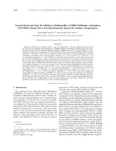
1.1 i5/OS IP packet filtering with secure shell The i5/OS IP packet filtering scenario uses a single System i with two network interfaces. One network connection is attached to a trusted network, the other to a non-trusted network. Note how IP packet filtering can protect resources above the network interface (Figure 1-1).
Figure 1-1 IP packet filtering implementation layers
1.1.1 Scenario characteristics This scenario presents a single System i for a business. The i5/OS implementation provides the untrusted business network a SSH server with limited telnet access. i5/OS only provides SSH services when the SSH server is enabled and for a specific static IPv4 address. This scenario has the following characteristics: One System i with two physical network interfaces. One network interface is connected to a trusted network, the other to an untrusted network. There is no firewall equipment in addition to the system i. Our scenario is using IPv4. IPv6 is disabled. We are only going to provide SSH access from a dynamic IP address (our technical support user) on the untrusted network (when enabled on i5/OS). SSH support is provided on an “as needed” basis.
1.1.2 Scenario objectives The objectives are: Provide a secure environment on i5/OS and the trusted network behind it. Improve security by deploying a SSH server on i5/OS. Provide a logging of attempted intrusions when the SSH server is not enabled. Allow a technical support user to access i5/OS and the trusted network on an “as needed” basis. 2
i5/OS Network Security Scenarios
1.1.3 Security policy Before creating a network security policy, you must have an IT security policy for the entire organization. Otherwise, you do not know what guidelines to follow. General security policies are: The default policy is to deny. Use high caution anytime a less trusted resource accesses a more trusted resource. Allow only what is needed. In our scenario, the only (untrusted) access is SSH when it is enabled. Hide theIP addressing with private IP addressing. Harden systems by disabling and removing unrequired resources. Push data to less trusted systems. Limit what data resides on less trusted systems. Encrypt data on systems. Log access and intrusion attempts. Intrusion detection system (IDS) is available for i5/OS. For systems accessed by untrusted sources, assume the system is fully compromised to help in your security design planning. Implement exit point programs when possible. Use i5/OS object security.
1.1.4 i5/OS security functions The following i5/OS security functions are used in this scenario:
Packet filtering lLogging Intrusion detection SSH services (encryption and tunneling)
1.2 IP packet filtering step-by-step set up This section describes the steps to configure the i5/OS for this scenario:
“Creating the untrusted Ethernet line” on page 3. “Creating the IP interface for untrusted network” on page 4 “Creating and starting IP filtering” on page 4 “Configuring the sshd IP address” on page 12 “Starting and stopping sshd” on page 12 “Configuring IPv6 to not auto start during IPL” on page 13 “Configuring IDS scan directives” on page 13
Creating the untrusted Ethernet line To create the Ethernet line description, find the resource name using the following command: WRKHDWRSC *CMN
Search for the resource name of communication resource type Ethernet port. In Figure 1-2 on page 4, the port we are configuring is CMN15. Create the Ethernet line description on our untrusted Ethernet network.
Chapter 1. i5/OS IP packet filtering
3
Figure 1-2 WRKHDWRSC *cmn on i5/OS CRTLINETH LIND(ETHLINE) RSRCNAME(CMN15) LINESPEED(*AUTO) DUPLEX(*AUTO)
Creating the IP interface for untrusted network Now create the TCP interface for the production interface of the Ethernet: ADDTCPIFC INTNETADR(‘10.10.10.12’) LIND(ETHLINE) SUBNETMASK(‘255.255.255.0’)
Creating and starting IP filtering 1. In the iSeries Navigator, select → Network → IP Policies (Figure 1-3).
Figure 1-3 iSeries Navigator packet rules
2. Right-click Packet Rules, and select Rules Editor.
4
i5/OS Network Security Scenarios
3. From the Welcome Packet Rules Configuration dialog, select Create a new packet rules file, and click OK (Figure 1-4).
Figure 1-4 Welcome - packet rules configuration
4. On the Getting Started dialog (Figure 1-5), click OK.
Figure 1-5 Packet filter - getting started
5. From the Insert menu, select Comment. Enter a description and click OK (Figure 1-6).
Figure 1-6 Packet filter - adding a comment
Chapter 1. i5/OS IP packet filtering
5
6. From the Insert menu, select Filter. Select set name of ssh_limit, action of PERMIT, direction of INBOUND, source address name of *, destination address name of * and click the Services tab (Figure 1-7). Use these entries to allow any IPv4 address to start an inbound connection to the SSH server on our production system from the ethline (untrusted) interface.
Figure 1-7 Packet filter - allow inbound ssh from untrusted (1 of 2)
7. Select the Service radio button. Select protocol of TCP/STARTING, source port of > 1023, destination port of = 22 (SSH server), and click OK (Figure 1-8).
Figure 1-8 Packet filter - allow inbound ssh from untrusted interface (2 of 2)
6
i5/OS Network Security Scenarios
8. From the Insert menu, select Filter. Select the set name of ssh_limit, action of PERMIT, direction of INBOUND, source address name of 10.10.10.12 (the sshd server address), destination address name of *, and click the Services tab (Figure 1-9). Use these entries to allow only IPv4 address telnet access from the sshd server on the production system.
Figure 1-9 Packet filter - adding ssh telnet permit (1 of 2)
9. Select the Service radio button. Select protocol of TCP/STARTING, source port of = *, destination port of = 23 (telnet server), and click OK (Figure 1-10). The asterisk denotes all available port numbers.
Figure 1-10 Packet filter - adding ssh telnet permit (2 of 2)
Chapter 1. i5/OS IP packet filtering
7
10.From the Insert menu, select Filter. Select set name of ssh_limit, action of PERMIT, direction of INBOUND, source address name of *, destination address name of *, and click the Services tab (Figure 1-11). Use these entries to allow any IPv4 address originating from the production system to the untrusted network.
Figure 1-11 Packet filter - adding new ssh inbound filter (1 of 2)
11.Select the Service radio button. Select protocol of TCP, source port of > 1023, destination port of = 22, and click OK (Figure 1-12).
Figure 1-12 Packet filter - adding new ssh inbound filter (2 of 2)
12.From the Insert menu, select Filter. Select set name of ssh_limit, action of PERMIT, direction of OUTBOUND, source address name of *, destination address name of *, and click the Services tab (Figure 1-13 on page 9). Use these entries to allow any IPv4 address originating from the production system to the untrusted network.
8
i5/OS Network Security Scenarios
Figure 1-13 Packet filter - adding new ssh outbound filter (1 of 2)
13.Select the Service radio button. Select protocol of TCP, source port of = 22, destination port of > 1023, and click OK (Figure 1-14).
Figure 1-14 Packet filter - adding new ssh outbound filter (2 of 2)
14.From the Insert menu, select Filter Interface. Select the line name of ETHLINE. Click the Filter Sets tab (Figure 1-15 on page 10). Use this entry to assign IPv4 IP filtering to the virtual Ethernet interface that connects to the untrusted network.
Chapter 1. i5/OS IP packet filtering
9
Figure 1-15 Packet filter - adding new ssh filter interface (1 of 2)
15.Select the filter set of ssh_limit and click Add. Click OK (Figure 1-16).
Figure 1-16 Packet filter - adding new ssh filter interface (2 of 2)
10
i5/OS Network Security Scenarios
16.The complete rule set appears as shown in Figure 1-17.
Figure 1-17 Packet filter - review ssh_limit rule set
Notes: – When you enter the Filter Interface, all other traffic is explicitly denied. – Ensure our rules are applied to the ETHLINE line description (untrusted) Note that other IPv4 protocols, such as UDP, ESP, AH, IPSEC IPCOMP, and RSVP are denied. 17.From the File menu, select Save. Assign the name SSH_LIMIT.I3P to our rules file. 18.From the File menu, select Activate Rules (Figure 1-18).
Figure 1-18 Activate packet filtering
Chapter 1. i5/OS IP packet filtering
11
19.To ensure IP filters are active, open the iSeries Navigator and select Network → IP Policies → Packet Rules. The right-hand pane displays the status of active packet rules loaded by the network interface name (Figure 1-19).
Figure 1-19 Packet filtering status
Note: IP filtering is not supported for IPv6 with i5/OS V5R4. If you do not useIPv6, ensure that it is disabled. To confirm that it is disabled, run the following command: ping ‘::1’. If the ping command receives replies, then disable IPv6. To disable it, run wrktcpsts, option 4, work with the IPv6 interface status, and enter 10=End by all Internet Addresses.
Configuring the sshd IP address If you have multiple IP addresses on your i5/OS, limit what IP address the ssh server will listen on. This simplifies our IP packet filtering rules when permitting telnet access from the 10.10.10.12 address (which is used by the ssh tunnel). Edit the sshd_config file by adding the following entry: ListenAddress 10.10.10.12
Starting and stopping sshd Run the CALL QP2TERM command, then go to the /QOpenSys/usr/sbin directory and run ./sshd to start sshd. To end sshd, find the active sshd job and run the ENDJOB command against it.
12
i5/OS Network Security Scenarios
Note: For a detailed discussion about starting and stopping sshd daemon, see Chapter 10, “Setting up and running the sshd daemon” on page 287.
Configuring IPv6 to not auto start during IPL By default, the i5/OS V5R4 IPL auto starts IP v4 and v6. The STRTCP command parameter default strip6 is *yes (start IPv6). To change this command parameter default, run the following command: CHGCMDDFT CMD(STRTCP) NEWDFT(‘STRIP6(*NO)’)
Configuring IDS scan directives Edit the file /qibm/userdata/os400/qos/etc/IDSPOLICY.CONFto include the following directives shown in Figure 1-20.
Figure 1-20 IDS scan rules for sshd attempts when inactive
Note: The IDS directives will only log the entries when the sshd server is inactive.
1.3 Verifying the IP packet filtering implementation To verify our limited ssh connection, do the following steps: 1. 2. 3. 4. 5.
Use a SSH client to access our public IP address of 10.10.10.12. Note the previous step will fail if the SSH server is inactive. Use a tunnelled telnet connection to connect to the telnet server (port 23). If there are other active servers, check if all other tunneled connections have failed. Verify that IDS logging is active when the sshd server is inactive.
1.4 Tips and techniques You must verify that your security policy is supported continually. Keep in mind that many network hosts might have IPv6 enabled by default. Therefore, ensure that you have security in place at each network host for IPv6. In addition to using IP filtering, implement the Intrusion Detection System (IDS) for i5/OS to provide additional network security auditing. Chapter 1. i5/OS IP packet filtering
13
If your IP filtering rules disable access to the iSeries Navigator or other important network access, enter the command RMVTCPTBL (Remove TCP/IP Table). Use caution because this command disables all IP packet filtering. To assist in troubleshooting the IPv4 filtering rules, use the journaling functionality that is available. The QIPFILTER journal logs entries when an IPv4 datagram matches a definition of a defined filter rule. To help mine the audit journal for intrusion monitoring, use the following commands: CPYAUDJRNE IM
This copies the im entries, if any, to qtemp/qauditim. RUNQRY *NONE QAUDITIM
This queries the im entries from qtemp/qauditim. For information about IDS and IP packet filtering, see the iSeries Information Center at: http://publib.boulder.ibm.com/infocenter/iseries/v5r4/index.jsp
For information about SSH, see IBM Portable Utilities for i5/OS in the Porting Central Web site at: http://www.ibm.com/servers/enable/site/porting/tools/openssh.html
14
i5/OS Network Security Scenarios
2
Chapter 2.
Building a DMZ with i5/OS This scenario describes a single System i with two i5/OS logical partitions (LPAR) with one partition in a demilitarized zone (DMZ) for Web application serving, and the other for production. This configuration provides a solution for businesses that require Web application serving to the Internet. Both the public and employees of the business can use Web application serving. This configuration is viewed as more secure because it separates the public servers from all internal systems. All public servers are placed in a network segment called a DMZ. In addition to security, availability is improved because the production partition is dedicated for batch processing or backup while the application server is still available.
© Copyright IBM Corp. 2007. All rights reserved.
15
2.1 i5/OS LPAR in DMZ You can implement the i5/OS LPAR in DMZ architecture discussed in this scenario by using a single System i with two logical partitions. One partition is for production and the other is for Web application serving (Figure 2-1).
Figure 2-1 Basic DMZ scenario
2.1.1 Scenario characteristics This scenario has the following characteristics: One System i with two logical partitions. One partition is for production and the other is for Web application serving. Four distinct networks - internal (trusted), virtual local area network (VLAN) (untrusted), DMZ (untrusted), and Internet (untrusted). The four are separated by a firewall and IP filtering on the virtual LAN. The router is connected to the Internet with a dedicated line. If intruders take control of the Web application server, they will only get a limited set of data (not the complete set of business data).They are not allowed to access any resource in the internal (trusted) network. The firewall provides packet filtering to the Web application server logical partition. The Web application server environment is limited from impacting the internal system resources. Each i5/OS partition has one physical network interface and a shared virtual Ethernet LAN interface. 16
i5/OS Network Security Scenarios
2.1.2 Scenario objectives The scenario objectives are: Provide a secure environment for i5/OS Web application services. Improve i5/OS Web application availability when dedicated batch processing and backups are being processed on production. Improve security because the public is not permitted to access any internal system direy. Only a portion of business data is available on the Web application server. Protect computer resources because the Web application server is separated from production resources. If the Web application server is compromised, prevent internal systems from intrusion.
2.1.3 Security policy Before you create your network security policy, you must have an IT security policy for your entire organization. Otherwise, you do not know what guidelines you must follow. General security policies are: The default policy is to deny. Use high caution anytime a less trusted resource accesses a more trusted resource. You allow only what is need. In our scenario, the only public (untrusted) access is to http and https. Hide IP addressing with private IP addressing. Harden systems by disabling and removing unrequired resources. Push data to less trusted systems. Limit what data resides on less trusted systems. Encrypt data in systems. Log access and intrusion attempts. Intrusion detection system (IDS) is available for i5/OS. For systems accessed by untrusted sources, assume the system is fully compromised to help in your security design planning. Limit IP traffic from Internet to DMZ systems. Eliminate inbound access completely for IP traffic from DMZ to internal systems. Minimize internal to DMZ system communication.
2.1.4 Firewall security functions The following functions (shipped with your firewall) are required to implement the network security in this scenario:
Packet filtering Port address translation (PAT) to DMZ partition Logging Optional: Intrusion detection and prevention
2.1.5 Web application server LPAR security functions The following functions for the Web application server LPAR are required to implement the network security in this scenario: HTTP powered by Apache Virtual local area network (VLAN) Chapter 2. Building a DMZ with i5/OS
17
2.1.6 Production LPAR security functions The following functions for the production LPAR are required to implement the network security in this scenario: IP packet filtering Virtual local area network (VLAN) Optional: Intrusion detection system (IDS)
2.2 Planning for implementation The firewall is implemented using a three port security device. The public Web application server is an i5/OS logical partition located in the DMZ and runs an HTTP server. This Web application server might be running the Apache HTTP server, ASF Tomcat, WebSphere Application Server, CGI (RPG, COBOL, and so on), or PHP. The production i5/OS logical partition is located in the internal trusted network and holds the complete set of business data. The Web application server receives its data updates when the production partition pushes updates to it. For security and availability reasons, the Web application server only contains a subset of the business data. One key reason to have a separate logical partition for Web application serving is to provide data availability when the production system is unavailable because of dedicated processing and data backups. The four networks require IP addressing assignments. This scenario uses the following addressing assignments:
18
Internal network 10.1.1.0/24 DMZ network 10.9.9.0/24 Virtual Ethernet 192.168.9.0/24 Public subnet 10.10.10.0/28 Firewall outside 10.10.10.50, DMZ 10.9.9.1, and internal 10.1.1.1 Web application server LPAR DMZ 10.9.9.2 and VLAN 192.168.9.2 Production LPAR internal 10.1.1.7 and VLAN 192.168.9.120
i5/OS Network Security Scenarios
Figure 2-2 illustrates this scenario with the required IP addresses.
Figure 2-2 Basic DMZ scenario with IP addressing
2.3 LPAR DMZ step-by-step set up This scenario involves two main tasks: “Configuring the production i5/OS LPAR partition” on page 19: – “Creating the virtual Ethernet line” on page 19 – “Creating the IP interface” on page 20 – “Creating and starting IP filtering” on page 20 – “Configuring IPv6 to not auto start during IPL” on page 28 “Configuring the DMZ logical partition network” on page 28: – “Creating the virtual Ethernet line” on page 29 – “Creating the IP interface” on page 29 – Configure and start the packet filters
2.3.1 Configuring the production i5/OS LPAR partition This section describes the steps we performed to configure the i5/OS logical partitions for this scenario.
Creating the virtual Ethernet line 1. To create the Ethernet line description, find the resource name. Run the following command: WRKHDWRSC *CMN
Chapter 2. Building a DMZ with i5/OS
19
2. Search for the communication resource type of 268C. Note the Ethernet port resource name. In Figure 2-3, the Ethernet port we are configuring is CMN09.
Figure 2-3 wrkhdwrsc *cmn on production LPAR
3. Create the virtual Ethernet line description on our virtual Ethernet network: CRTLINETH LIND(VETH0) RSRCNAME(CMN09) LINESPEED(*AUTO) DUPLEX(*AUTO)
Creating the IP interface Now create the TCP interface for the production interface of the virtual Ethernet: ADDTCPIFC INTNETADR(‘192.168.9.120’) LIND(VETH0) SUBNETMASK(‘255.255.255.0’)
Creating and starting IP filtering 1. In the iSeries Navigator, select → Network → IP Policies (Figure 2-4).
Figure 2-4 iSeries Navigator packet rules
20
i5/OS Network Security Scenarios
2. Right-click Packet Rules, and select Rules Editor (Figure 2-5).
Figure 2-5 Welcome - Packet Rules Configuration window
3. From the Welcome Packet Rules Configuration dialog, select Create a new packet rules file, and click OK to receive the Getting Started dialog (Figure 2-6). Click OK.
Figure 2-6 Packet filter - Getting Started
4. From the Insert menu, select Comment. Enter a description and click OK (Figure 2-7).
Figure 2-7 Packet filter - adding a comment
Chapter 2. Building a DMZ with i5/OS
21
From the Insert menu, select Address. Enter an address name, defined address of Subnet, the subnet address, the subnet mask, and click OK (Figure 2-8). This helps describe the DMZ subnet addresses.
Figure 2-8 Packet filter - adding an address
5. From the Insert menu, select Filter. Select set name of VLAN_DMZ, action of DENY, direction of INBOUND, source address name of *, destination address name of *, and click the Services tab (Figure 2-9). Use these entries to prevent any IPv4 address from starting an inbound connection to the production LPAR from the DMZ subnet.
Figure 2-9 Packet filter - denying inbound from VLAN DMZ (1 of 2)
22
i5/OS Network Security Scenarios
6. Select the Service radio button. Select protocol of TCP/STARTING, source port of = *, destination port of = *, and click OK (Figure 2-10). The asterisk denotes all available port numbers.
Figure 2-10 Packet filter - denying inbound from VLAN DMZ (2 of 2)
7. From the Insert menu, select Filter. Select set name of VLAN_DMZ, action of PERMIT, direction of INBOUND, source address name of = *, destination address name of = *, and click the Services tab (Figure 2-11). Use these entries to allow any IPv4 address originating from the production LPAR to the DMZ subnet.
Figure 2-11 Packet filter - adding new inbound filter (1 of 2)
Chapter 2. Building a DMZ with i5/OS
23
8. Select the Service radio button. Select protocol of TCP, source port of 1023, and click OK (Figure 2-12).
Figure 2-12 Packet filter - Adding new inbound filter (2 of 2)
9. From the Insert menu, select Filter Interface. Select the line name of VETH0. Click Filter Sets tab. Use this entry to assign IPv4 IP filtering to the virtual Ethernet interface that connects to the DMZ subnet. 10.From the Insert menu, select Filter. Select set name of VLAN_DMZ, action of PERMIT, direction of OUTBOUND, source address name of = *, destination address name of = *, and click the Services tab (Figure 2-13). Use this entry to allow any IPv4 address originating from the production LPAR to the DMZ subnet.
Figure 2-13 Packet filter - Adding new outbound filter (1 of 2)
24
i5/OS Network Security Scenarios
11.Select the Service radio button. Select protocol of TCP, source port of > 1023, destination port of /var/run/l2tp-control
This tells the l2tpd daemon to connect the connection named i5os. 4. At this point, obtain an IP address for the new ppp0 interface. To begin routing remote traffic over IPSec using the new ppp0 interface, type: sles10:/ # route add -net 0.0.0.0 dev ppp0
4.3.8 Verifying the L2TP connection To see if the L2TP/PPP connection via IPSec is successful: 1. Type: sles10:/ # ifconfig
If L2TP/PPP is successful, you see an interface named ppp0 in the list of interfaces available. 2. To verify the L2TP/PPP traffic is protected by ESP start tcpdump, watch the traffic from/to the i5/OS VPN server address 10.55.1.1. sles10:/ # tcpdump host 10.55.1.1
3. Now start traffic via our related ppp0 address (this time we were issued 192.168.100.202). To test ICMP traffic with ESP, type: sles10:/ # ping 192.168.100.55
The tcpdump shows the following entries (Figure 4-14) when traffic is protected by encapsulated security protocol (ESP).
hh:mm:ss.ssssss IP sles10.itso.com > i5os.itso.com: ESP(spi=0x485d7113, seq=ox14e), length nnn hh:mm:ss.ssssss IP i5os.itso.com > sles10.itso.com: ESP(spi=0x8b22a8bd, seq=0x152), length nnn
Figure 4-14 tcpdump view of ESP protected network traffic
Notice that there are two different security parameter index (SPI) IDs in use. One is for inbound traffic and the other is for outbound traffic. The SPI tells the kernel which encryption rule and algorithm to use on the traffic tagged with SPI. 4. Now test a TCP/IP application. sles10:/ # telnet 192.168.100.55
You see similar ESP packets again going back and forth between Linux and i5/OS (Figure 4-14).
Chapter 4. VPN tunnel between Linux and i5/OS
77
4.3.9 Stopping the Linux L2TP connection To stop our l2TP connection: 1. Type: sles10:/ # echo “d i5os” > /var/run/l2tp-control
This disconnects the i5/OS L2TP/PPP connection, removed the default route assigned to the ppp0 interface, and removes the ppp0 interface. 2. To end l2tpd when running interactively, press Ctrl+c. 3. To end l2tpd when running in the background, type: sles10:/ # killall l2tpd.
4.3.10 Stopping the Linux IPSec connection To stop the ipsec2i5os connection: 1. Type: sles10:/ # ipsec auto --down ipsec2i5
2. To stop the IPSec Openswan subsystem, type: sles10:/ # ipsec setup --stop
4.4 Tips and techniques It is important to verify that your security policy is continually maintained. For information about security, see the Networking security topic in the V5R4 Information Center at: http://publib.boulder.ibm.com/infocenter/iseries/v5r4/index.jsp?topic=/rzahg/rzahgicinet2.h tm
78
i5/OS Network Security Scenarios
5
Chapter 5.
VPN connection with Windows XP clients This chapter describes how to implement secure connections for travelling employees and virtual office employees that need access to the corporate office. The remote users (clients) access the corporate office i5/OS system (server) using a PC with Microsoft® Windows XP. Windows XP does not support VPN/IPSec host-to-gateway connections; therefore, to achieve the gateway functionality, this scenario requires using the Layer 2 Tunneling Protocol (L2TP) in addition to IPSec. For that same reason, the VPN connection in the i5/OS system is configured as a host-to-host connection. L2TP allows remote clients to get an IP address from a pool of addresses defined at the gateway system and therefore, to communicate with all hosts (IP addresses) that are configured in the L2TP profile. This extends the capabilities of the VPN connection from host-to-host to host-to-gateway. You can use a combination of VPN connections and L2TP profiles to define which networks are accessed by the remote user. Note: The scenario described in this chapter refers to a VPN connection between a Windows XP client and an i5/OS gateway system. However, this particular configuration is also applicable to VPN connections started from Windows Server® 2003 systems, when they play the role of VPN initiator (client) and the i5/OS acts as the VPN responder (server).
© Copyright IBM Corp. 2007. All rights reserved.
79
5.1 Scenario description This scenario describes two alternatives for connecting the client to the Internet: Connection over a dedicated link, for example, a dedicated high speed link (DSL) or cable modem. This is a good option for small offices or virtual offices where employees telecommute from their home. Connection over a dial-up PPP link. This option is suitable for travelling employees that dial to the Internet service provider (ISP) over a telephone line to establish the connection. Note: In both cases, the ISP assigns the client a dynamic (random) IP address. Figure 5-1 provides an overview of the scenario described in this chapter.
Travelling employee
Internet
Trusted Network
VPN tunnel
ISP
VPN tunnel
ISP
Corporate office
Employee’s home office
Figure 5-1 Virtual office and travelling employees connected to corporate office over a VPN tunnel
5.1.1 Scenario objectives The objectives of this scenario are: IPSec must protect all traffic between the remote Windows XP clients and the corporate gateway i5/OS system. The company’s private address space must assign remote clients an internal IP address. The company’s policies control access to the company’s resources for internal hosts. The i5/OS VPN gateway at the corporate office uses proxy ARP to route traffic between the remote clients and the internal network.
5.1.2 Scenario characteristics The characteristics of this scenario are: Traveling employees access the corporate office by dialing an ISP Point of Presence (PoP). Telecommuters and small remote offices access the corporate office by a DSL or cable modem connection to the ISP. The ISP assigns dynamic IP addresses to the remote clients. In this scenario, we are assuming that the ISP has assigned an IP address of 10.1.1.4 to the client. This is not a real public address. We are using it for example purposes. 80
i5/OS Network Security Scenarios
The corporate office gateway runs on i5/OS V5R4. The internal corporate network IP address is 192.168.100.0/24. The private IP address for the corporate gateway system is 192.168.100.10. The corporate gateway system accesses the Internet using IP address 10.55.1.1. This is not a real public address. We are using it for example purposes). The VPN connections is only started from the remote Windows XP systems, playing the VPN initiator role. When the VPN connection is established, the corporate gateway system assigns a private IP address to the remote client from the pool of addresses defined in the L2TP profile. Note: To simplify this scenario’s configuration, a security gateway between the i5/OS system at the corporate office and the Internet is not shown, but it is assumed. Figure 5-2 shows the network configuration used in this scenario.
Corporate Network 192.168.100.0/24
ISP
RCHAS55
.9
10.55.1.1 .55
Internet
PC1 10.1.1.4
ISP
192.168.100.xxx
IPSec VPN responder
VPN initiators
VPN tunnel
L2TP
Figure 5-2 Network configuration for VPN connection between i5/OS and Windows clients
5.1.3 Software prerequisites The following software requirements are used for the VPN connection described in this scenario.
Chapter 5. VPN connection with Windows XP clients
81
i5/OS system Th requirements are:
i5/OS V5R4 (5722-SS1) Digital Certificate Manager V5R4 (5722-SS1 option 34) TCP/IP Connectivity Utilities for i5/OS V5R4 (5722-TC1) iSeries Access for Windows V5R4 (5722-XE1) iSeries Navigator
Windows XP system The requirements are: Microsoft Windows XP Professional Version 2002 SP2 Microsoft Management Console 2.0 Version 5.1 SP2 – Snap-in for IPSecurity Monitor
5.2 Planning for implementation The following planning checklists illustrate the type of information you need before you begin configuring VPN. All answers on the prerequisite checklist must be “Yes” before you proceed with the VPN setup. Table 5-1 System requirements (i5/OS system) Prerequisite checklist (i5/OS system)
Answers
Is your operating system i5/OS V5R4 (5722-SS1)?
Yes
Is iSeries Access for Windows (5722-XE1) installed?
Yes
Is iSeries Navigator installed?
Yes
Is the Network subcomponent of iSeries Navigator installed?
Yes
Is TCP/IP Connectivity Utilities for i5/OS (5722-TC1) installed?
Yes
Have you applied the latest program temporary fixes (PTFs)?
Yes
Did you set the retain server security data (QRETSVRSEC *SEC) system value to 1?
Yes
Is TCP/IP configured on your i5/OS system (including IP interfaces, routes, local host name, and local domain name)?
Yes
Is normal TCP/IP communications established between the required endpoints?
Yes
If the VPN tunnel traverses firewalls or routers that implement IP packet filtering, do the firewall or router filter rules support AH and ESP protocols?
Yes
Are the firewalls configured to enable IP forwarding?
Yes
Do you have the proper authorities to administer packet rules on your i5/OS system?
Yes
Table 5-2 VPN configuration on the i5/OS system
82
VPN configuration checklist (i5/OS system)
Answers
What type of VPN connection would you like to create?
host-to-host
i5/OS Network Security Scenarios
VPN configuration checklist (i5/OS system)
Answers
What name will you assign to the dynamic-key group (individual VPN data connection between pair of endpoints)?
VPNC01
What Internet Key Exchange (IKE) policy do you want to use to protect your keys?
Balanced security and performance
Are you using certificates to authenticate the connection? If no, what is the preshared key? Note: All clients must use the same preshared key.
No certificates; preshared key is VPNCLIENTKEY
What is the identifier (IP type and IP address) of the local key server?
IP version 4 10.55.1.1
What is the identifier (IP type and IP address) of the local connection endpoint?
IP version 4 10.55.1.1
What is the identifier (IP type and IP address) of the remote key server?
IP version 4 Any address
What is the identifier (IP type and IP address) of the remote connection endpoint?
IP version 4 Any address
What are the ports and protocols of the data that this connection will protect?
Any
What data policy do you want to use to protect the data?
Balanced security and performance
What characteristics are used for IKE Phase 1 policy (key protection)? a. Authentication method b. Encryption algorithm c. Hash algorithm d. Diffie-Hellman group e. Keys lifetime f. IKE negotiation mode
a). Preshared key b). DES and 3DES c). MD5 and SHA d). Group 1 e). 1 day f). Main mode
What characteristics are used for IKE Phase 2 policy (data protection)? a. Protocol b. Encapsulation mode c. Keys lifetime d. Keys life size limit e. Diffie-Hellman perfect secrecy used?
a). ESP b). Transport c). 1 hour d). No size limit e). No
To which interfaces on the local system does this connection apply?
ETHLIN1
Table 5-3 L2TP configuration on the i5/OS system L2TP configuration checklist (i5/OS system)
Answers
What is the name of the L2TP profile?
L2TPLNS01
What is the mode type of the L2TP profile
L2TP terminator
What is the local tunnel endpoint IP address?
10.55.1.1
What is the name of the virtual L2TP line description?
L2TPLNS01
Will the system be using tunnel keep alive messages?
Yes
What is the local host name?
RCHAS55
What is the maximum number of sessions for this L2TP profile?
5
What is the inactivity time-out for remote access users?
No time-out
Chapter 5. VPN connection with Windows XP clients
83
L2TP configuration checklist (i5/OS system)
Answers
What is the local IP address of the i5/OS system on the local network?
192.168.100.10
What is the IP address pool for remote access users?
192.168.100.200 192.168.100.204
What protocol is used to authenticate remote access users?
CHAP-MD5
What is the name of the validation list used to authenticate remote access users?
L2TPVL001
What user names and passwords will be added to this validation list? Note: User names and passwords are used for CHAP authentication. Make them unique for each client.
craig/itsasecret ... ...
Will the system allow remote users to access other networks (IP forwarding)?
Yes
Table 5-4 VPN configuration on the Windows XP system VPN configuration checklist (Windows XP system)
Answers
What name will you assign to the new VPN connection?
rchas55
What is the IP address of the VPN server?
10.55.1.1
What is the type of this connection?
L2TP IPSec VPN
What are the IPSec settings for this connection (for example, authentication method for IKE Phase 1)? Note: The preshared key must be the same as on the i5/OS system.
Preshared key: VPNCLIENTKEY
Does the VPN connection require dialing another connection first?
No
What user name and password will be used to start this connection? Note: User names and passwords used for CHAP authentication. Make them unique for each client.
craig/itsasecret
Is this connection available to all users or only for a specific user?
All users
5.2.1 Implementation task summary This scenario describes the following tasks:
“Configuring the VPN connection on the i5/OS system” on page 84 “Verifying the system-wide VPN responding policy on the i5/OS system” on page 92 “Configuring the L2TP profile on the i5/OS system” on page 94 “Configuring the VPN connection on the Windows XP system” on page 105 “Starting the VPN server on the i5/OS system (responder)” on page 113 “Starting the VPN connection on the Windows XP system (initiator)” on page 117
5.3 Step-by-step set up guide The following sections describe steps you need to configure and activate the VPN connection for this scenario.
5.3.1 Configuring the VPN connection on the i5/OS system This section shows how to use the iSeries Navigator functions to create and configure the VPN connection on the i5/OS system (VPN responder). 84
i5/OS Network Security Scenarios
You create and configure the VPN connection by using the New Connections wizard of the iSeries Navigator. To perform this task, use the information from your VPN planning checklist (Table 5-2 on page 82). The steps are: 1. Start an iSeries Navigator session: Start → Programs → IBM iSeries Access for Windows → iSeries Navigator. 2. In the iSeries Navigator window, select the i5/OS system that you will use as the VPN initiator by clicking its corresponding icon. In this example, we are using system RCHAS55. 3. If the Sign-on to iSeries prompt appears, enter your user ID and password and then click OK to complete the sign-on. 4. In the navigation pane of the iSeries Navigator, expand My Connections → servername → Network → IP Policies. The expanded window is similar to Figure 5-3.
Figure 5-3 Expanded window of IP Policies tasks
5. In the expanded navigation pane, right-click Virtual Private Networking. 6. In the context menu for Virtual Private Networking, click New Connection (Figure 5-4).
Figure 5-4 Context menu for Virtual Private Networking - New Connection
Chapter 5. VPN connection with Windows XP clients
85
7. The welcome window of the New Connection wizard displays (Figure 5-5).
Figure 5-5 New Connection Wizard - Welcome window
8. Review the Welcome window of the wizard for information about the objects that the wizard will create and click Next to begin the wizard. 9. When the Connection Name window appears, take the following actions: a. In the Name field, enter VPNC01. b. Optionally, specify a description for this connection group. c. After you have enter this information, click Next to continue (Figure 5-6).
Figure 5-6 New Connection Wizard - Connection Name window
86
i5/OS Network Security Scenarios
10.When the Connection Scenario window appears, select Connect your host to another host and click Next to continue (Figure 5-7).
Figure 5-7 New Connection Wizard - Connection Scenario window
11.When the Internet Key Exchange Policy window displays in that window (Figure 5-8): a. Select Create a new policy. b. Select Balance security and performance. c. Click Next to continue. Note: If you get an error message stating “The certificate request could not be processed”, ignore it because in this scenario you are not using certificates for the key exchange in the VPN.
Figure 5-8 New Connection Wizard - Internet Key Exchange Policy window
Chapter 5. VPN connection with Windows XP clients
87
12.Optional step: If you have certificates installed on your i5/OS system, you see the Certificate for Local Connection Endpoint window (Figure 5-9). If this window displays, select No to indicate that you will not use certificates to authenticate the VPN connection and click Next.
Figure 5-9 New Connection Wizard - Certificate For Local Connection Endpoint window
13.When the Local Key Server window appears (Figure 5-10): a. In the Identifier type field, select IP version 4 address. b. In the IP address, select 10.55.1.1. c. After these selections, click Next.
Figure 5-10 New Connection Wizard - Local Key Server window
88
i5/OS Network Security Scenarios
14.When the Remote Key Server window appears (Figure 5-11): a. In the Identifier type field, select Any IP address. b. In the Pre-shared key field, enter VPNCLIENTKEY. c. After you have entered this information, click Next to continue.
Figure 5-11 New Connection Wizard - Remote Key Server window
15.When the Data Services window displays (Figure 5-12): a. In Local port field, enter 1701. b. In Remote port field, enter 1701. c. In Protocol field, select UDP. You need to specify these values because LT2P uses UDP port 1701. This setting ensures that only L2TP traffic is allowed and protected by this VPN connection. As mentioned at the beginning of this chapter, the gateway functionality in this scenario is accomplished by using an L2TP tunnel protected by an IPSec VPN connection. d. Click Next to continue.
Figure 5-12 New Connection Wizard - Data Services window
Chapter 5. VPN connection with Windows XP clients
89
16.The Data Policy window displays (Figure 5-13). Select Create a new policy, select Balance security and performance, and click Next.
Figure 5-13 New Connection Wizard - Data Policy window
17.The Applicable Interfaces window appears (Figure 5-14). From the list of lines and interfaces, select ETHLIN1 by clicking its corresponding check mark box.
Figure 5-14 New Connection Wizard - Applicable Interfaces window
90
i5/OS Network Security Scenarios
18.At this point, you have specified all the parameters needed by the wizard and they are displayed on the New Connection Summary window (Figure 5-15). Review them to ensure they are correct. If you need to change something, click Back to go to the previous windows and make the corrections. When all the attributes are correct, click Finish to complete the configuration.
Figure 5-15 New Connection Wizard - New Connection Summary window
Chapter 5. VPN connection with Windows XP clients
91
19.When the Activate Policy Filters dialog box appears (Figure 5-16), select No, packet rules will be activated at a later time and click OK.
Figure 5-16 New Connection Wizard - Activate Policy Filters dialog box
You have now completed the task of configuring VPN on the i5/OS system.
5.3.2 Verifying the system-wide VPN responding policy on the i5/OS system The i5/OS VPN Key Manager function uses a single system-wide responding Internet Key Exchange (IKE) policy, which defines the algorithms that the system will use when responding to incoming IKE requests, specifically, when performing IKE Phase 1 negotiation. In this scenario, the i5/OS is acting as the VPN responder for connections started by the Windows XP systems (VPN initiators). Therefore, the system-wide policy is used for all connections. The following steps guide you through the configuration of the VPN responding policy: 1. In the iSeries Navigator, expand My Connections → servername → Network → IP Policies → Virtual Private Networking → IP Security Policies and right-click Internet Key Exchange Policies.
92
i5/OS Network Security Scenarios
2. From the Internet Key Exchange Policies context menu (Figure 5-17), click Responding Policy.
Figure 5-17 Selecting the Responding Policy option from the Internet Key Exchange window
3. On the General tab (Figure 5-18), review the options and select or deselect them as needed to fit your needs.
Figure 5-18 Responding Internet Key Exchange Policy - General tab
Chapter 5. VPN connection with Windows XP clients
93
4. Click the Algorithm tab (Figure 5-19) and review the hash and encryption algorithms.
Figure 5-19 Responding Internet Key Exchange Policy - Algorithms tab
5. When you have selected the options for your environment, click OK to complete the verification and customization of the VPN system-wide responding policy. It is important to understand that the IKE policies generated by the New VPN Connection wizard (associated to specific IP addresses or groups of addresses) are only used for VPN connections initiated by the local i5/OS system and have no effect when the connection is started by a remote system, such as the scenario mentioned here. The system-wide responding policy is the only policy that specifies what incoming IKE requests the i5/OS system accepts.
5.3.3 Configuring the L2TP profile on the i5/OS system The gateway functionality for this scenario is accomplished by using an L2TP tunnel, protected by the VPN/IPSec connection. This section explains how to configure the L2TP Network Server (LNS) end of the L2TP tunnel.
94
i5/OS Network Security Scenarios
To perform this task, use the information from your VPN planning checklist (Table 5-3 on page 83) and follow these steps: 1. In the navigation pane of the iSeries Navigator (Figure 5-20), expand My Connections → servername → Network → Remote Access Services, right-click Receiver Connection Profiles, and select New Profile from the context menu.
Figure 5-20 Selecting New Profile from the context menu of receiver Connection Profiles
2. When the New Point-to-Point Connection Profile Setup window displays (Figure 5-21): a. b. c. d.
Select PPP. Select L2TP (virtual line). In the Operating mode field, select Terminator (network server). In the Type of line service field, select Single line.
Figure 5-21 New Point-to-Point Connection Profile Setup window
3. Click OK to continue.
Chapter 5. VPN connection with Windows XP clients
95
4. When Once the New Point-to-Point Profile Properties window appears (Figure 5-22), take the following actions on the General tab: a. In the Name field, enter VL2TPLNs01. b. Optionally, specify a description for this L2TP profile.
Figure 5-22 New Point-to-Point Profile Properties window - General tab
5. Click the Connection tab. 6. In the Connection tab of the New Point-to-Point Profile Properties window: a. In the Maximum number of connections field, specify the desired value (5 in this scenario). b. In the Local tunnel endpoint IP address field, select 10.55.1.1. c. In the Virtual line name field, select L2TPLNS01.
96
i5/OS Network Security Scenarios
After you select the virtual name, the New L2TP Line Properties window (Figure 5-23) appears automatically. If not, click Open to display the line properties.
Figure 5-23 New Point-to-Point Profile Properties window - Connection tab
Chapter 5. VPN connection with Windows XP clients
97
7. You are now working with the properties of the new LT2P virtual line associated with the L2TP profile you are creating. In the General tab of the line properties window (Figure 5-24), enter meaningful text in the description for this line.
Figure 5-24 New L2TP Line Properties window - General tab
8. Click the Link tab.
98
i5/OS Network Security Scenarios
9. In the Link tab of the line properties window (Figure 5-25), select Activate tunnel keep alive. Important: Do not skip this step. Make sure that the Activate tunnel keep alive check box is selected to ensure that the i5/OS ends the L2TP tunnel when a remote connection ends. If the Activate tunnel keep alive option is not selected and the connection terminates abnormally (for example, if the user shuts down Windows XP without first ending the VPN connection), the connection on the i5/OS system remains active and other clients cannot use the connection.
Figure 5-25 New L2TP Line Properties window - Link tab
10.Click the Authentication tab.
Chapter 5. VPN connection with Windows XP clients
99
11.In the Authentication tab of the line properties window (Figure 5-26), enter the local host name of the i5/OS system (in this scenario, we are using RCHAS55 as the host name). Note: L2TP tunnel authentication is not needed when the L2TP tunnel is being protected by IPSec.
Figure 5-26 New L2TP Line Properties window - Authentication tab
100
i5/OS Network Security Scenarios
12.Click OK to save the virtual line settings and return to the L2TP Profile Properties window (Figure 5-27).
Figure 5-27 New Point-to-Point Profile Properties window - Connection tab
13.In the L2TP profile properties window, click the Authentication tab. 14.In the Remote system authentication section (Figure 5-28 on page 102): a. Select Require this iSeries server to verify the identity of the remote system. b. Select Authenticate locally using a validation list. c. Verify that Allow encrypted password (CHAP-MD5) is selected. d. Enter a value for the Validation list name (in this scenario, we are using L2TPVL001) and click New to create and configure this validation list.
Chapter 5. VPN connection with Windows XP clients
101
Figure 5-28 New Point-to-Point Profile Properties window - Authentication tab
15.When the New Validation List window (Figure 5-29) appears, click Add.
Figure 5-29 New Validation List window
102
i5/OS Network Security Scenarios
16.To add a new user to the validation list, select Require encrypted password (EAP or CHAP-MD5) and then enter the user name and a password (Figure 5-30). This user is not related to i5/OS user profiles. It is the user and password that the remote Windows XP client uses to establish the VPN connection with the i5/OS gateway.
Figure 5-30 Add a user to the new validation list
17.Click OK. 18.Enter the password for the new user again on the password confirmation prompt (Figure 5-31).
Figure 5-31 Password confirmation prompt
Chapter 5. VPN connection with Windows XP clients
103
19.Click OK to save the new user into the validation list. The updated validation list displays (Figure 5-32). If you need to add another user, click Add.
Figure 5-32 New Validation List window after a user has been added
20.After you finish adding users, click OK to return to the New Point to Point Profile Properties window. 21.Click the TCP/IP Settings tab.
104
i5/OS Network Security Scenarios
22.On the TCP/IP Settings tab (Figure 5-33): a. In the Assign fixed IP address field, select 192.198.100.10 (IP address of the i5/OS system on the local network). b. In the IP address assignment method field, select Address pool. c. In the starting IP address field, enter 192.168.100.200 (in this scenario, our pool of IP addresses for remote VPN access users goes from 192.168.199.200 to 192.168.204). d. In the Number of addresses, enter 5. e. Select Allow remote system to access other networks (IP forwarding).
Figure 5-33 New Point-to-Point Profile Properties window - TCP/IP Settings tab
23.Click OK to complete. The new L2TP profile is now created and configured. You have now completed the task of configuring the L2TP profile on the i5/OS system.
5.3.4 Configuring the VPN connection on the Windows XP system This section shows how to create and configure the VPN connection on the Windows XP system (VPN initiator). The VPN connection is created and configured by using the New Connection Wizard of Windows XP. To perform this task, use the information from your VPN planning checklist (Table 5-4 on page 84). The steps are: 1. On the Microsoft Windows XP task bar, click Start → Programs → Accessories → Communications → New Connection Wizard.
Chapter 5. VPN connection with Windows XP clients
105
2. The New Connection Wizard welcome window appears (Figure 5-34). Click Next to continue.
Figure 5-34 New Connection Wizard - Welcome window
3. Select Connect to the network at my workplace (Figure 5-35) and click Next.
Figure 5-35 New Connection Wizard - Connection type window
106
i5/OS Network Security Scenarios
4. Select Virtual Private Network connection (Figure 5-36) and click Next.
Figure 5-36 New Connection Wizard - Workplace™ connection type window
5. In the Company Name field (Figure 5-37), enter the name of the i5/OS gateway system (in this scenario, we are using RCHAS55 as the gateway name), click Next.
Figure 5-37 New Connection Wizard - Connection name window
Chapter 5. VPN connection with Windows XP clients
107
6. Optional step: If you see the window shown in Figure 5-38, select Do not dial the initial connection and click Next. This option specifies whether the Windows XP workstation is connected through a LAN or dial-up interface to the Internet. If you do not have a cable or DSL connection to the Internet, select the PPP configuration for dialing into the ISP.
Figure 5-38 New Connection Wizard - Public Network window
7. In the VPN Server Selection window (Figure 5-39), enter the IP address of the i5/OS gateway system (in this scenario, we are using 10.55.1.1 as the gateway’s IP address) and click Next.
Figure 5-39 New Connection Wizard - VPN Server Selection window
108
i5/OS Network Security Scenarios
8. When you have completed the previous steps, the wizard is ready to create the connection (Figure 5-40). If you want to have a shortcut for this connection on your desktop, select Add a shortcut to my desktop. Click Finish to create the VPN connection and close the wizard.
Figure 5-40 New Connection Wizard - Completion window
9. The Connect window (Figure 5-41) automatically appears after finishing the wizard. At this point, you have configured the VPN connection and the LT2P tunnel on the Windows XP system. However, before trying to establish a connection, you need to change connection properties that did not appear during the wizard configuration. To do these changes, click Properties on the Connect window.
Figure 5-41 Connect window
Chapter 5. VPN connection with Windows XP clients
109
10.The VPN Connection Properties window appears (Figure 5-42).
Figure 5-42 VPN Connection Properties - General tab
11.Click the Security tab (Figure 5-43) and deselect the Require data encryption (disconnect if none) check box.
Figure 5-43 VPN Connection Properties - Security tab
110
i5/OS Network Security Scenarios
12.Click IPSec Settings. 13.In the IPSec Settings window (Figure 5-44), select the Use pre-shared key for authentication check box and enter the preshared key (in this scenario, the key is VPNCLIENTKEY). Note: The preshared key must be the same as the one on the i5/OS system.
Figure 5-44 IPSec Settings window
14.Click OK to return to the VPN Connection Properties window. 15.Click the Networking tab. 16.In the Type of VPN field (Figure 5-45), change the value from Automatic to L2TP IPSec VPN and click Settings to change the PPP properties.
Figure 5-45 VPN Connection Properties - Networking tab
Chapter 5. VPN connection with Windows XP clients
111
17.In the PPP Settings window (Figure 5-46), deselect both Enable software compression and Negotiate multi-link for single-link connections.
Figure 5-46 PPP Settings
18.Click OK to return to the VPN Connection Properties window (Figure 5-47).
Figure 5-47 VPN Connection Properties - Networking tab
112
i5/OS Network Security Scenarios
19.Click OK to return to the Connect window (Figure 5-48).
Figure 5-48 Connect window
20.Click Cancel to close the Connect window without establishing the VPN connection. The steps needed to start the connection are described in the next sections. You have now completed the task of configuring the VPN connection on the Windows XP system.
5.3.5 Starting the VPN server on the i5/OS system (responder) When you have configured the new VPN connection and the L2TP profile on the i5/OS systems, you need to activate the resources needed to establish the secured VPN connections initiated by the remote Windows XP systems. Follow these steps to activate the resources needed by your new VPN connection: 1. In the iSeries Navigator (Figure 5-49), expand My Connections → servername → Network and then click IP Policies to display the status of Virtual Private Networking on the right pane.
Figure 5-49 Virtual Private Networking status
Chapter 5. VPN connection with Windows XP clients
113
2. If the status of Virtual Private Networking is Stopped on the right pane of IP Policies, right-click Virtual Private Networking and click Start (Figure 5-50).
Figure 5-50 Starting VPN on the i5/OS system (responder)
3. The status of Virtual Private Networking changes to Started. 4. Expand My Connections → servername → Network → Remote Access Services and click Receiver Connection Profiles (Figure 5-51) to display the status of the receiver connection profiles on the right pane.
Figure 5-51 Receiver Connection Profiles
114
i5/OS Network Security Scenarios
5. If the status of the L2TPLNS01 profile is Inactive, right-click L2TPLNS01 and click Start on the profile’s context menu (Figure 5-52).
Figure 5-52 Starting the L2TP profile
6. The status of the L2TPLNS01 profile changes to Waiting for connection requests. 7. Expand My Connections → servername → Network → IP Policies. 8. In the navigation pane (Figure 5-53), right-click Packet Rules and on the context menu, click Activate Rules.
Figure 5-53 Activating Packet Rules (IP filtering)
Chapter 5. VPN connection with Windows XP clients
115
9. When the Activate Packet Rules window appears (Figure 5-54): a. Select Activate only the VPN generated packet rules. b. Select Activate these rules on the following interface. c. In the Interface field, select ETHLIN1.
Figure 5-54 Activate Packet Rules window
10.Click OK to activate the VPN generated rules. 11.The IP packet filtering rules for your VPN are now active. The appear in the right pane (Figure 5-55).
Figure 5-55 VPN packet rules activated
You have now completed the task of starting the VPN server on the i5/OS system (responder).
116
i5/OS Network Security Scenarios
5.3.6 Starting the VPN connection on the Windows XP system (initiator) To establish the VPN connection on the Windows XP system: 1. On the Microsoft Windows XP task bar, click Start → Programs → Administrative Tools → Services. 2. Verify that the status for IPSEC Services is Started (Figure 5-56). If not, start this service because it is a prerequisite for establishing VPN connections on the Windows XP system.
Figure 5-56 Services window
3. On the Microsoft Windows XP task bar, click Start → Programs → Accessories → Communications → Network Connections. 4. On the right pane, right-click RCHAS55 (the VPN connection created for this scenario) and then click Connect on the context menu (Figure 5-57).
Figure 5-57 Network Connections window
Chapter 5. VPN connection with Windows XP clients
117
5. The Connect window appears (Figure 5-58). Enter the user name and password required for this VPN connection and click Connect to start the connection. Note: The user name and password are case-sensitive. They were created in 5.3.3, “Configuring the L2TP profile on the i5/OS system” on page 94.
Figure 5-58 Connect window
The VPN connection is successfully established using the L2TP tunnel and protected by IPSec. To confirm that this connection has the expected host-to-gateway functionality, you can start a telnet session to a system in the corporate network (for example, to the system with IP address 192.168.100.9). You have now completed the task of starting the VPN connection on the Windows XP system (initiator).
5.4 Verifying the implementation This section describes the functions that are available to verify the VPN connection created for this scenario.
5.4.1 Verifying connectivity on the Windows XP system There are several ways to verify the VPN connection on the Windows XP system (initiator).
ipconfig command You can use the ipconfig command to verify the IP address that is assigned to your workstation. The steps are: 1. Click Start → Programs → Accessories → Command Prompt. 2. On the Command prompt window, enter ipconfig and press Enter. The information returned by the ipconfig command is similar to Example 5-1 on page 119. 118
i5/OS Network Security Scenarios
Example 5-1 ipconfig output
Ethernet adapter Local Area Connection 2: Connection-specific DNS Suffix . : IP Address. . . . . . . . . . . . : 10.1.1.4 Subnet Mask . . . . . . . . . . . : 255.255.255.0 Default Gateway . . . . . . . . . : 10.1.1.1 PPP adapter rchas55: Connection-specific DNS Suffix . : IP Address. . . . . . . . . . . . : 192.168.100.200 Subnet Mask . . . . . . . . . . . : 255.255.255.255 Default Gateway . . . . . . . . . :
The IP address of the PPP adapter represents the address assigned from the L2TP Network Server (LNS) on the i5/OS system.
IP Security Monitor Another way to check whether a secured connection is established and what type of protection is using the Microsoft Management Console, in combination with the IP Security Monitor snap-in. The steps are: 1. On the Microsoft Windows XP task bar, click Start → Run. The Run window appears (Figure 5-59). 2. Enter mmc and click OK.
Figure 5-59 Starting the Microsoft Management Console
Chapter 5. VPN connection with Windows XP clients
119
3. The Console window appears (Figure 5-60).
Figure 5-60 Microsoft Management Console window
4. On the console menu (Figure 5-61), click File and then click Add/Remove Snap-in.
Figure 5-61 Adding a new snap-in to the console
120
i5/OS Network Security Scenarios
5. When the Add/Remove Snap-in window (Figure 5-62) displays, click Add.
Figure 5-62 Add/Remove Snap-in window
6. The Add Standalone Snap-in window appears (Figure 5-63). Scroll down the list of available standalone snap-ins and click IP Security Monitor to select this snap-in. Click Add to add it to the console.
Figure 5-63 Add Standalone Snap-in window
Chapter 5. VPN connection with Windows XP clients
121
7. Click Close to return to the Add/Remove Snap-in window (Figure 5-64). 8. On the Add/Remove Snap-in window, click OK to complete the add snap-in process.
Figure 5-64 Add/Remove Snap-in window adding IP Security Monitor snap-in
9. The Console window (Figure 5-65) now shows the IP Security Monitor snap-in.
Figure 5-65 Microsoft Management Console window, after adding IP Security Monitor snap-in
10.Expand the console tree to IP Security Monitor → workstation → Main Mode and click Security Associations.
122
i5/OS Network Security Scenarios
The security associations for main mode displays on the details pane as shown in Figure 5-66. These are the IPSec values negotiated when the VPN connection was established at IKE Phase 1 (for example, the authentication method, the hash, and encryption algorithms that are providing key protection).
Figure 5-66 Security Associations for IKE Phase 1 (main mode)
11.In the navigation pane of the Console window, expand IP Security Monitor → workstation → Quick Mode and click Security Associations. The security associations for quick mode display on the details pane as shown in Figure 5-67. These are the IPSec values negotiated at IKE Phase 2 (for example, the mechanism that is providing data protection). Note: L2TP uses UDP port 1701. Seeing this port displayed in the security associations for quick mode confirms that all the traffic across the L2TP tunnel is protected by IPSec.
Figure 5-67 Security Associations for IKE Phase 2 (quick mode)
Network Connections interface Another mechanism to verify the VPN connection is described in the following steps: 1. On the Microsoft Windows XP task bar, click Start → Programs → Accessories → Communications → Network Connections.
Chapter 5. VPN connection with Windows XP clients
123
2. On the right pane, right-click RCHAS55 (the VPN connection created for this scenario) and click Status on the context menu (Figure 5-68).
Figure 5-68 Network Connections window
3. The Connection Status window (Figure 5-69) displays, showing statistics about the connection.
Figure 5-69 Connection Status window - General tab
4. Click the Details tab. The Details tab (Figure 5-70 on page 125) information shows what kind of IPSec protocol is used to protect the data traffic. In this case, the data is protected by the Encapsulated Security Payload (ESP) protocol, which also encrypts the encryption key length, thus providing additional security. The DES encryption algorithm with a key length of 56 bits is used to encrypt the data traffic. 124
i5/OS Network Security Scenarios
Figure 5-70 Connection Status window - Details tab
5. Click Close to close the Connection Status window.
5.4.2 Verifying connectivity on the i5/OS system To verify the VPN connection on the i5/OS system, use the iSeries Navigator.
Verifying IPSec attributes To verify the IPSec attributes of your VPN connection: 1. From the Navigation pane of the iSeries Navigator, expand My Connections → servername → Network → IP Policies → Virtual Private Networking → Secure Connections.
Chapter 5. VPN connection with Windows XP clients
125
2. Click All Connections. The list of current connections will be displayed on the right pane as shown in Figure 5-71. The characters after the name of each connection identify the initiator (“:L” meaning local, “:R” meaning remote). For example, the connection established in this scenario appears as VPNC01:R4. The R means that the connection has been established from a remote system (the Windows XP workstation). The number after the R (4 in this example) represents a number for the connection and changes each time a connection is established. A restart of the VPN server resets the numbering.
Figure 5-71 Virtual Private Networking - All Connections
3. On the right pane (Figure 5-72), right-click VPNC01:R4 and click Properties to display the IPSec/IKE attributes of your VPN connection.
Figure 5-72 Virtual Private Networking - Displaying the properties of a remote connection
126
i5/OS Network Security Scenarios
4. The IKE attributes of your VPN connection display (Figure 5-73).
Figure 5-73 VPN Properties - Current attributes of the VPN/IPSec connection
5. Click OK to close the Connection Properties window. 6. From the Navigation pane of the iSeries Navigator, expand My Connections → servername → Network → TCP/IP Configuration → IPv4. 7. Click Interfaces. The list of TCP/IP interfaces defined in your system displays on the right pane as shown in Figure 5-74.
Figure 5-74 TCP/IP Configuration - Interfaces
Chapter 5. VPN connection with Windows XP clients
127
8. On the right pane (Figure 5-75), right-click 10.55.1.1 (the public IP address of your i5/OS gateway system) and click Active Packet Rules to display the IP packet filtering attributes of your VPN connection.
Figure 5-75 TCP/IP Configuration - Interfaces
9. The Active Packet Rules window (Figure 5-76) displays, showing the IP packet filtering rules applied on the interface used by your VPN connection. Both inbound and outbound packet rules are listed.
Figure 5-76 Active Packet Rules
128
i5/OS Network Security Scenarios
10.From the list in the Outbound section (Figure 5-77), select the VPNC01:R4 entry (the entry associated to your remote VPN connection) and click Security Associations.
Figure 5-77 Active Packet Rules
11.The Filter Security Associations window (Figure 5-78) displays. You can see that a single VPN connection between two systems uses an inbound and an outbound security association (SA). The security parameter index (SPI) in conjunction with the IP address is used in IPsec-protected IP packets to find the corresponding SA on the VPN connection endpoint. You can also notice that both SAs (inbound and outbound) are using the Encapsulation Security Payload (ESP) protocol to protect the traffic across the VPN connection.
Figure 5-78 Filter Security Associations
Chapter 5. VPN connection with Windows XP clients
129
12.Select the Outbound entry and click Properties to see additional IPSec details (Figure 5-79).
Figure 5-79 Filter Security Associations
13.The additional IPSec attributes of your VPN connection display similar to those in Figure 5-80.
Figure 5-80 Security Association Properties
14.Click Close to return to the Filter Security Associations window. 15.On the Filter Security Associations window, click Close to return to the Active Packet Rules window. 16.On the Active Packet Rules window, click Cancel to return to the iSeries Navigator.
130
i5/OS Network Security Scenarios
Verifying L2TP attributes To verify the L2TP attributes of the connection: 1. From the Navigation pane of the iSeries Navigator, expand My Connections → servername → Network → Remote Access Services. 2. Click Receiver Connection Profiles to see the list of L2TP profiles in your system (Figure 5-81). Your L2TP profile has a status of Active Connections.
Figure 5-81 Receiver Connection Profiles - Status of L2TP profiles
3. On the right pane (Figure 5-82), right-click L2tplns01 and click Connections to display information about the connections using this L2TP profile.
Figure 5-82 Displaying information about L2TP connections
Chapter 5. VPN connection with Windows XP clients
131
4. The L2TP Connections window displays (Figure 5-83) showing details of your L2TP connection, such as the status and the IP addresses for both sides of the L2TP tunnel.
Figure 5-83 L2TP Connections - Details
5. Click OK to close the L2TP Connections window and return to the iSeries Navigator.
5.5 Tips and techniques You can use most of the tools and functions described in 5.4, “Verifying the implementation” on page 118 for VPN troubleshooting. If you experience problems when implementing or using your VPN connections, see Troubleshooting VPN in the V5R4 Information Center at: http://publib.boulder.ibm.com/infocenter/iseries/v5r4/topic/rzaja/rzajatroubleshootvpn.htm
132
i5/OS Network Security Scenarios
6
Chapter 6.
Password elimination using Windows 2003 KDC Single Sign-on (SSO) represents different things and in different implementations. In this book, we use the term in the perspective of password elimination. In a network of multiple systems, or servers, each has its own way of authentication that involves a password. This existence of ‘multiple passwords for ‘the same user or server” causes headaches for both users and network and security administrators and great security hazards. By “password elimination SSO - SSO realized through password elimination”, we suggest a scenario where this problem is fixed by eliminating multiple passwords for a single user or server. We use the Network Authentication Services (NAS) and the Enterprise Identity Mapping (EIM) to realize this concept. This chapter starts with a brief explanation of a password elimination SSO implementation. You can also find a practical basic scenario updated for V5R4 on how to implement the SSO on iSeries Access (5250 telnet and its related host servers) and on iSeries NetServer™. Finally, we cover how to back up your EIM domain to ensure high availability of your SSO solution. For explanations related to the Kerberos and EIM, see Windows-based Single Sign-on and the EIM Framework on the IBM eserver iSeries Server, SG24-6975.
© Copyright IBM Corp. 2007. All rights reserved.
133
6.1 What is SSO? In a typical environment today, most employees have multiple user profiles and passwords to remember. Each time they access a system, they must supply their ID and password to access the resources on that system. Single sign-on (SSO) allows a computer user to sign on when at the start of the day with no prompting for additional sign-on requests or challenges for additional passwords for the rest of the day. We have not reached that perfect status: not all applications support this solution. However, we are close to making the implementation of SSO worthwhile. 6.6, “Single sign-on tips” on page 234 provides a list of i5/OS applications that are SSO-enabled. Starting with OS/400 V5R2, several services were enabled to function in a SSO environment. iSeries Access and NetServer, for example, are enabled for SSO. However, that implementation was weak because those services utilize SSO if the Microsoft Windows user ID matches the i5/OS user profile name and the passwords between the systems match. This SSO is different from the older concept of SSO. It is not a password cache or a user and password synchronization. Here, the same user can run on his workstation on any number of applications already enabled for SSO that can access without being prompted for a user ID or password - even if his user ID in those applications is entirely different from his Windows user ID. One of the unique characteristics for this i5/OS SSO solution is that you can eliminate the password (for example, by setting it to *NONE). This provides the greatest value and potentially a less risky security exposure. In this type of SSO, both the client and server make use of a network-authentication authority to control access to network resources. i5/OS service takes advantage of the Network Authentication Services (NAS). All the applications can use the Enterprise Identity Mapping (EIM) to find the corresponding user ID starting from the Windows one. Another characteristic of this password elimination SSO is that you do not have to switch everyone over simultaneously. You combine with other SSO solutions for other systems or applications. Password elimination SSO solution does not rely on user ID and password synchronization or caching. EIM works if a person has a different user ID on every system or application accessed that is enabled for SSO. The EIM architecture allows you to define relationships between individuals and entities in the enterprise. It is an enabling technology infrastructure and not a solution by itself. Put simply, EIM is a look-up table where each user’s various identities in user registries (different platforms and applications) are mapped to a single identifier. EIM-enabled applications can use this table to associate the identity certified by Kerberos with the identity in its own user registry and allow the user to proceed without further challenges. The reasons to implement password elimination are to reduce the number of calls to the Help Desk about password management and the potential cost to manage it over time. However, implementing password elimination SSO solution enforces security letting you manage stronger passwords because users only have to create and remember one, making them less likely to write the passwords down. The downside is that if users do not lock their workstations when they walk away, anyone can use and access the workstation enabled for SSO. If you are concerned about this, consider that it is also an issue in the absence of SSO. If a user walks away from a workstation after signing into three systems, you still have risks.
134
i5/OS Network Security Scenarios
6.2 Scenario description Figure 6-1 shows a customer network schema.
Figure 6-1 SSO scenario
In this scenario, we implement a password elimination Single Sign-on solution to let users authenticate themselves only at the Windows domain and to use iSeries applications without other challenges. We take advantage of the Windows Active Directory® users domain authentication that is already set up and working in the customer network on the user’s Windows 2003 servers. We enroll two i5/OS systems (one used for production and the other one for testing) in the Active Directory to participate in the Kerberos authentication. Microsoft Active Directory is the most common component that provides Kerberos support so we will use it in our scenario. Unknown to many users and administrators, Kerberos is implemented in Microsoft Windows 2000 and 2003 Servers and Windows 2000 and XP clients. When you install and set up the Active Directory server on your Microsoft Windows 2000 or 2003 server, you are also configuring the Kerberos server. Kerberos on a Windows server platform uses the Active Directory and the Microsoft implementation of the Lightweight Directory Access Protocol (LDAP) to store all information about principals on the Kerberos realm. You must enroll the Active Directory in the Windows client workstation to be part of the Windows domain.
Chapter 6. Password elimination using Windows 2003 KDC
135
Password elimination single sign-on solution is not an “all or none” solution. One of its strengths is the granularity of its implementation. We suggest to set up and test it with a few client workstations and then spread the solution for those users and applications where it can make a difference. In our scenario, we test the password elimination SSO implementation with one user and for the iSeries Access (both telnet 5250 and iSeries Access) and NetServer applications.
6.3 Planning for implementation Before starting the configuration, there are considerations and checks to do. This scenario assumes that: There is a Windows domain already configured and that each user has his own user ID enrolled in the Active Directory server. There is a DNS server correctly populated with all hosts on the customer network and that all the hosts refer to it. These are the most common implementations that you can find in the real world. We configure only one i5/OS and one user to show the configuration steps required and to test the Kerberos implementation. For your network, configure the Kerberos only for a few client workstations at the beginning to test it and propagate the configuration later on the other ones because the password elimination SSO solution is not an “all or none” implementation.
6.3.1 Products prerequisites This section discusses the requirements.
i5/OS prerequisites This scenario is based on the V5R4 i5/OS level and the following are the licensed program options you must install:
5722-SS1 Option 12 - Host Servers 5722-SS1 Option 30 - QShell Interpreter 5722-XE1 iSeries Access for Windows 5722-TC1 TCP/IP Connectivity Utilities for iSeries
In V5R4, license program products 5722-AC3, Cryptographic Access Provider and 5722-CE3, and SSL Client Encryption at 128-bit are no longer required. The function of the first one is now integrated into the operating system, while the function of the second one is integrated into 5722-XE1, iSeries Access for Windows. Note: In this scenario, we use a Windows 2003 Server as a Kerberos key distribution center (KDC) server. Starting with V5R3, you can use i5/OS as a Kerberos server, which means 5722-SS1 Option 33 i5/OS - PASE is required. In V5R4, the Kerberos network authentication server is shipped as a separate product, 5722-NAE Network Authetication Enablement. For more information, see Setting up a Kerberos server in i5/OS PASE in the V5R4 Information Center at: http://publib.boulder.ibm.com/infocenter/systems/scope/i5os/index.jsp?topic=/rzakh/rzakh scenpase.htm
136
i5/OS Network Security Scenarios
To verify that the required products are installed on i5/OS, from an iSeries Navigator session, expand your system connection → Configuration and Service → Software → Installed products.
Windows server prerequisites In this scenario, we use a Windows 2003 server, but even with the Windows 2000 server, these considerations are valid. We assume that on those servers, the Active Directory has already been installed and configured with a Windows domain. In addition, the Windows Kerberos support tools need to be explicitly installed. Follow these steps to install the necessary Windows 2003 Server Kerberos support tools. The steps for installing these Kerberos support tools on other Windows operating systems are similar. Place the Windows 2003 Server CD into the CD-ROM drive on the server. Navigate to the CDROM\Support\Tools directory. The window you see looks similar to Figure 6-2.
Figure 6-2 Windows 2003 Server support tools directory
Double-click the setup.exe file. In this scenario, the file is netsetup.exe. Follow the default installation instructions until the support tools are installed. We recommend that you verify that the specific support tools have been installed. There are several useful commands to debug Kerberos problems, but the most important one is ktpass, which is a prerequisite requirement to modify the Active Directory account that creates an associated Kerberos principal. To verify that the ktpass command has been installed, follow these steps: 1. Click Start in the lower-left corner of the window. 2. Select Search and then Files and Folders.
Chapter 6. Password elimination using Windows 2003 KDC
137
3. In the Search for files or folders named field, enter ktpass. 4. Make sure that the Look in field holds the value of the drive where the operating system is is installed. 5. Click Search Now. The search results returns a reference to the ktpass command stored in C\ProgramFIles\Support Tools, as shown in Figure 6-3.
Figure 6-3 Search result for the ktpass command
Verify that the support tools directory is in the Windows operating system’s path environment variable. Follow these steps: 1. 2. 3. 4.
138
Right-click My Computer and click Properties. Click the Advanced tab at the top of the window. Click Environmental Variables. In the System Variables, scroll to the Path variable and click Edit.
i5/OS Network Security Scenarios
The value is C:\Program Files\Support Tools\ as shown in Figure 6-4.
Figure 6-4 Path environment variable showing Support Tools
Windows clients prerequisites The Windows clients must authenticate to a Windows domain, such as Windows XP Professional or Windows 2000. Windows 98 clients cannot do true SSO. However, you can load the Massachusetts Institute of Technology (MIT) Kerberos for Windows code to implement ticket caching and handle authenticating to Kerberos. It requires two sign-ons. All the applications that you have decided to use with the Kerberos authentication will open the connection without having to sign-on again. Note: Windows 95 does not support Kerberos.
6.3.2 Before starting Before starting with the configuration of SSO on iSeries, verify the host name resolution and synchronize the system’s time in the network.
Chapter 6. Password elimination using Windows 2003 KDC
139
Host name resolution For Kerberos (and EIM) to properly work on your network, you must have a reliable IP address/host name resolution process. Note that: You must have DNS names in lowercase and the real name (Windows domain) in uppercase. This is important because the Kerberos is case-sensitive and the DNS process is not. The reserve name resolution is required. The host name is solved with the IP address and vice-versa. Using DNS gives you a single point to manage your name resolution, rather than having to make host entries in the host file on each of the workstations or systems in your network. Either verification technique works, but the DNS server method provides a more reliable, easier to manage solution for your name resolution. You can implement a DNS server on a variety of platforms, including i5/OS. For more information, see i5/OS IP Networks: Dynamic, SG24-6718. 1. To determine how your iSeries host name resolves, check your iSeries system’s host domain properties as shown in Figure 6-5. 2. From the iSeries Navigator, expand your system connection → Network → TCP/IP Configuration and click to select Properties.
Figure 6-5 Host Domain Information window
Note that if you want modify the host and domain name shown, put the new value between single quotes (‘) so that i5/OS keeps the lowercase characters specified. Also notice that there is an ordered list of IP addresses for DNS servers. Having more than one DNS server in the network is useful for a better and reliable environment.
140
i5/OS Network Security Scenarios
Now verify how this system’s i5/OS name is being resolved in the network so that Kerberos-based transmissions are successful. 3. To determine how the DNS server is resolving the host name, run a Name Server Lookup (nslookup) command. Open a command prompt on the your PC, click Start → Run, and then type cmd when prompted. This opens the command window. T 4. Type nslookup, and press the Enter key. Type the fully qualified domain name of the iSeries that is used as the EIM domain controller and press the Enter key. This returns the TCP/IP address that the DNS is using for the iSeries, including the case of each of the characters (uppercase or lowercase). If the host name that has been used is an exact match with what you saw in Figure 6-5 on page 140, your resolution satisfies the Network Authentication Service and Kerberos requirements. If not, you can change either your iSeries host name and domain name to the value returned by the nslookup function, or change your DNS server to resolve to the name listed in the Host Domain Information window. 5. To verify that the DNS record is complete, from the same nslookup prompt that you used, type the command set type=ptr and press the Enter key. 6. Type the TCP/IP address that was returned from the iSeries fully qualified domain name. If the IP address returned is different than the one you used in the first nslookup, or there is not a resolution, contact the administrator of the DNS to correct the record. See Figure 6-6 for an example of the nslookup verification.
Figure 6-6 nslookup command output
Note: Not all DNS servers have the pointer (PTR) record for the reverse resolution. Single sign-on requires both A and PTR records in DNS before it works. If either is missing, contact the DNS server administrator and correct the issue.
Chapter 6. Password elimination using Windows 2003 KDC
141
Synchronizing system times When using Kerberos for network authentication in your network, setting the time and time zone values on all your servers is an absolute requirement. Kerberos protocol uses time stamps and time skew values (difference in time values) as part of its security implementation. The maximum time skew allowed by default in Kerberos is 300 seconds (five minutes). If your server is outside this maximum skew, then Kerberos authentication fails. On all servers, the time value, time zone, and time skew values are configurable. You can raise the time skew to a maximum of 900 seconds in the iSeries Network Authentication Service configuration, which we describe in 6.4.1, “Configuring NAS” on page 145. On i5/OS, check and synchronize the following time and time zone system values with the rest of your network: QDATETIME or QTIME QUTCOFFSET: The Coordinated Universal Time Offset from the Greenwich mean time Before synchronizing service times in the network (corresponds to i5/OS QDATETIME or QTIME system values), check that the i5/OS QUTCOFFSET system value is set according to your time zone. This system values keeps track of how many hours you are away from Greenwich mean time or, as it is officially called, Coordinated Universal Time Offset. This is used by servers to change the time stamp to match your time. Prior to V5R3, the coordinated universal time offset was controlled by the QUTCOFFSET system value. Now, this system value is displayed only and you cannot change it. Instead of it, modify the QTIMZON system value. This system value specifies the time zone information used to calculate local system time. All current settings contain either the Standard Time or Daylight Saving Time values, depending on whether or not Daylight Saving Time is in effect. In addition, starting in V5R3, i5/OS automatically adjusts the QTIME on the Daylight Saving Time change. You can synchronize the system times on servers within the Kerberos realm by changing the KDC time using the Windows operating system date and time interface and the QTIME system value to change the iSeries system time. However, to keep system times in a network synchronized more easily, we recommend that you set up a Simple Network Time Protocol (SNTP) server in your network. SNTP allows multiple systems to base their time on a single time server.
142
i5/OS Network Security Scenarios
On a Windows system, you can use NET HELP TIME from a DOS command window to access the SNTP setup: 1. To set up the iSeries to retrieve its time from an SNTP server, from an iSeries Navigator session, expand your system connection → Network → Servers → TCP. All the TCP servers are displayed in the right pane. Right-click the SNTP client server, select Properties, and select the Client folder (Figure 6-7).
Figure 6-7 SNTP Properties window
2. Enter the fully qualified name of a SNTP server in your network in the Time servers field. This might be an external SNTP server. There are many public time servers in the Internet. You can search for them with a query, such as “NTP server”. Starting in V5R3, i5/OS can be both an SNTP client and an SNTP server. The default Poll interval is 60 minutes, which is satisfactory for most implementations. 3. Select the General folder and select Client in the SNTP services to start when the TCP/IP is started. Click OK to continue. When you are changing the SNTP properties, we recommend that you stop (if active) and start the iSeries SNTP server job: 1. From an iSeries Navigator session, expand your system connection → Network → Servers → TCP. Right-click the SNTP client server, select Stop, and then Start. 2. Using our iSeries Navigator properties example, the iSeries SNTP client server now polls the SNTP server every 60 minutes and adjusts its software and hardware clock.
Chapter 6. Password elimination using Windows 2003 KDC
143
Gathering information Collect the information shown in Table 6-1before starting the configuration of necessary services to activate password elimination single sign-on solution on your iSeries. Table 6-1 Information to collect before starting the configuration Item
Information to collect
Example values
A
What is the name of the Kerberos default realm to which the iSeries will belong? (The default is the domain name converted to uppercase.)
ITSO.COM
B
What is the KDC Kerberos for this default realm?
Win2003Server1
C
What is the KDC fully qualified host name?
Win2003Server1.itso.com
D
What is the port on which the KDC listens?
88 (default value)
E
What is the password server for this KDC?
Win2003Server1
F
What is the port of your password server?
464 (default value)
G
What is your iSeries host name?
rchas08
H
What is the iSeries fully qualified host name?
rchas08.itso.com
I
What services do you want to kerberized?
5250 Telnet and iSeries Navigator iSeries NetServer
We will use the values in the right column for our scenario. Before users can input to EIM first, they must be identified. Users will have their user names on many systems that need to be collected. EIM provides a matching of all the principal user names in a master record. These user names are called associations and the master record is called the EIM identifier. Depending on the different types of systems involved, there are various ways of collecting lists of user IDs. This poses a problem for the systems administrator. Because SSO is a scalable solution, we suggest you start with a few users to test the environment and spread the solution over the entries using the steps in the next section. In this scenario, we want to test SSO with user May Smith.
6.4 Step-by-step setup guide Enable the single sign-on on i5/OS on an application. Avoiding password authentication is the target of this scenario. To reach this goal, you need to configure: iSeries Network Authentication Service (NAS) to set up an iSeries server to accept Kerberos authenticated tickets. Enterprise Identity Mapping (EIM) that allows the same user to have different user IDs on various servers in the network. Both service configurations are done through an iSeries Navigator interface.
144
i5/OS Network Security Scenarios
6.4.1 Configuring NAS This section provides information about how to configure NAS.
Setting up on i5/OS To start the iSeries Navigator Network Authentication Service wizard on your client workstation, you must have the iSeries Navigator Security component installed on the client workstation. The iSeries Navigator Security component is not required on a workstation that initiates an iSeries Navigator session using Kerberos authentication. Note: On the iSeries Navigator session that you use to set up the Network Authetication Service, ensure that the name of your system connection is your iSeries host’s fully qualified name that is known and published by your DNS servers. Perform the following steps: 1. In an iSeries Navigator session, expand your system connection → Security. Right-click Network Authentication Service and select Configure. If you see the Reconfigure option instead of Configure, it indicates that the Network Authentication Service has already been configured. You can either reconfigure it (the reconfiguration proceeds in a similar way to configuration), or you can right-click Network Authentication Service and select Properties to verify that the current configuration is appropriate for your network. 2. The Network Authentication Service configuration wizard welcome window opens. Read the information and click Next.
Chapter 6. Password elimination using Windows 2003 KDC
145
3. In the Specify Realm Information window, as shown in Figure 6-8, enter the name of the realm that serves as your default Kerberos realm, parameter A. In this scenario, it is ITSO.COM. Select Microsoft Active Directory is used for Kerberos authentication because it reflects the implementation in this scenario. Click Next. Note: The Windows 2000 KDC is case-sensitive and the name of the realm is always in uppercase. Under standard conventions, the name of the realm is the domain name, which is converted to uppercase.
Figure 6-8 NAS wizard configuration - Specify realm information
146
i5/OS Network Security Scenarios
4. In the Specify KDC Information window, shown in Figure 6-9, enter the fully qualified host and domain name of your Active Directory server that acts also as the Kerberos Key Distribution Center (KDC), parameter C. Win2003Server1.itso.com is the domain name in our scenario. Enter the port number, parameter D. The default port for Kerberos is 88. Unless your KDC has been configured to listen on a port other than the default, you do not need to change this parameter. Click Next.
Figure 6-9 NAS configuration wizard - Specify KDC information
Chapter 6. Password elimination using Windows 2003 KDC
147
5. The next window, shown as Figure 6-10, gives you the option to allow principals to change the Kerberos passwords remotely. If you want to allow clients to change passwords, select Yes in the Specify Password Server Information window. The window fields appear already filled in with the default values and with Yes already selected. The configuration wizard also keeps valid the KDC server name for the password server and leaves 464 as the default port. Check the information collected in the table“Gathering information” on page 144, parameters E and F, if password server name or port is different than the ones proposed. Modify the necessary fields. Click Next.
Figure 6-10 NAS configuration wizard - Specify password server information
6. The Select Keytab Entry window lets you select which services on your i5/OS the wizard enables for Kerberos authentication, parameter F. A keytab file is populated with the name of the principals selected and their passwords are required in the next window. Read this wizard window text for the keytab file definition.
148
i5/OS Network Security Scenarios
In our scenario, we only enable the iSeries Kerberos Authentication and the iSeries NetServer as shown in Figure 6-11. Also, LDAP and HTTP servers that are powered by Apache can use Kerberos tickets to authenticate. If your current plans are to enable those services for Kerberos authentication, it might save you time to check the boxes in this step. We do not follow that path for these two “additional services” in this chapter. However, if you checked LDAP and HTTP server powered by Apache, you see two additional windows that prompt you for the passwords for those two principals. For the principals that you want to select, ensure that you document those passwords because you need to supply them in the KDC configurations. In our example, select only the iSeries Kerberos Authentication and the iSeries NetServer check boxes, then click Next.
Figure 6-11 NAS configuration wizard - Select keytab entries
Chapter 6. Password elimination using Windows 2003 KDC
149
7. In the Create iSeries Keytab Entry window, shown in Figure 6-12, specify the password for the corresponding Kerberos principal displayed. That is, its shared secret. Note that the Keytab field in the Create iSeries Keytab Entry window shows the path to the keytab file that the wizard will generate. Enter the password twice for verification because it is not displayed. Click Next.
Figure 6-12 NAS configuration wizard - Create i5/OS keytab entry
150
i5/OS Network Security Scenarios
8. A similar window asks you to enter the password for the iSeries NetServer principal, as you can see in Figure 6-13. Notice that the wizard automatically adds the i5/OS name, fully qualified name, and IP address, both for host and Common Integrated File System (CIFS) entries. This is because both Windows 2000 and Windows XP support Kerberos V5, but they require different user names to be defined for the principals to create. Windows 2000 systems look for a service principal that the user name portion of the principal has defined as the host. Clients running the XP operating system look for user names with CIFS. Enter the password twice for verification and click Next.
Figure 6-13 NAS configuration wizard - Create NetServer keytab entry
Chapter 6. Password elimination using Windows 2003 KDC
151
9. The default is shown in the next window in Figure 6-14, with the Yes option selected. The NAS configuration wizard allows you to create a batch file. If you execute that file on the Windows KDC server, it adds the iSeries applications as Active Directory accounts. It creates the associated Kerberos principal entries. The default batch file is C:\Documents and Settings\All Users\Documents\IBM\Client Access\NASConfig_Rchas08.bat, but you can modify the path or the name file. Include password in the batch file is also checked as the default. Notice that the passwords are in clear text in the batch file. Thus, we recommend to delete the batch file from the Kerberos server and your PC right after you use it. If you do not include the password in the batch file, a prompt for inserting the password appears when you run the batch file on the Kerberos server. You can select No and do it manually, but it requires configuration on the Active Directory and manual operations to add i5/OS service principals to the Kerberos server.
Figure 6-14 NAS configuration wizard - Create batch file
10.Click Next.
152
i5/OS Network Security Scenarios
11.The final step is to verify the entries in the Configuration Summary window (Figure 6-15). Review the setting values. Use Back if you need to go back and make changes. When satisfied with all the setting values, click Finish.
Figure 6-15 NAS configuration wizard - Summary window
12.The messages shown in Figure 6-16 remind you of activities to be performed on the Windows Kerberos server to complete the Kerberos setup. Click OK and the NAS configuration wizard is completed.
Figure 6-16 NAS configuration wizard message
Chapter 6. Password elimination using Windows 2003 KDC
153
To verify the ITSO.COM realm settings you just created, expand your system connection → Security. Right-click Network Authentication Service and click Realms and the ITSO.COM realm appears in the right pane. By right-clicking on it and selecting Properties, you can review the values input in the configuration wizard as shown in Figure 6-17.
Figure 6-17 Realm properties
All these settings are stored in the Integrated File System in the file /QIBM/UserData/OS400/NetworkAuthentication/krb5.conf.
Enrolling the i5/OS services on the KDC To complete the enrollment of the i5/OS services to the Windows domain and to take advantage of the ticket authentication of the Kerberos server, there are two methods. You can manually add the service principals, or as this scenario illustrates, you can launch the batch file of the windows KDC server as mentioned in Step 9 on page 152. In this scenario the batch file is C:\Documents and Settings\All Users\Documents\IBM\Client Access\NASConfig_Rchas08.bat. In Example 6-1, you can see the details of the file. Notice that the passwords of the service principals are in plain text. Example 6-1 NASConfig_Rchas08.bat file @ECHO ECHO ECHO ECHO ECHO. ECHO ECHO ECHO ECHO
154
OFF IBM grants you a nonexclusive copyright license to use all programming code examples from which you can generate similar function tailored to your own specific needs. All sample code is provided by IBM for illustrative purposes only. These examples have not been thoroughly tested under all conditions. IBM, therefore, cannot guarantee or imply reliability, serviceability, or function of these programs.
i5/OS Network Security Scenarios
ECHO. ECHO ECHO ECHO ECHO ECHO. ECHO. ECHO ECHO ECHO ECHO. ECHO. ECHO. @ECHO
All programs contained herein are provided to you "AS IS" without any warranties of any kind. The implied warranties of non-infringement, merchantability and fitness for a particular purpose are expressly disclaimed.
NOTE:
If any of the commands fail, such as KTPASS or SETSPN, make sure that the directories that contain these commands are included in the user's PATH statement on the KDC server.
ON
setlocal set WINVER=2003 ver | find "2000" >nul if not errorlevel 1 set WINVER=2000 if %WINVER%==2000 ( NET USER rchas08_1_krbsvr400 navigator /ADD /workstations:none /DOMAIN KTPASS -MAPUSER rchas08_1_krbsvr400 -PRINC krbsvr400/
[email protected] -PASS navigator -mapop set NET USER rchas08_2_HOST netserver /ADD /workstations:none /DOMAIN KTPASS -MAPUSER rchas08_2_HOST -PRINC HOST/
[email protected] -PASS netserver -mapop set NET USER rchas08_3_cifs netserver /ADD /workstations:none /DOMAIN KTPASS -MAPUSER rchas08_3_cifs -PRINC cifs/
[email protected] -PASS netserver -mapop set NET USER rchas08_4_HOST netserver /ADD /workstations:none /DOMAIN KTPASS -MAPUSER rchas08_4_HOST -PRINC HOST/
[email protected] -PASS netserver -mapop set NET USER rchas08_5_cifs netserver /ADD /workstations:none /DOMAIN KTPASS -MAPUSER rchas08_5_cifs -PRINC cifs/
[email protected] -PASS netserver -mapop set NET USER rchas08_6_HOST netserver /ADD /workstations:none /DOMAIN KTPASS -MAPUSER rchas08_6_HOST -PRINC HOST/
[email protected] -PASS netserver -mapop set NET USER rchas08_7_cifs netserver /ADD /workstations:none /DOMAIN KTPASS -MAPUSER rchas08_7_cifs -PRINC cifs/
[email protected] -PASS netserver -mapop set NET USER rchas08_8_HOST netserver /ADD /workstations:none /DOMAIN KTPASS -MAPUSER rchas08_8_HOST -PRINC HOST/
[email protected] -PASS netserver -mapop set NET USER rchas08_9_cifs netserver /ADD /workstations:none /DOMAIN KTPASS -MAPUSER rchas08_9_cifs -PRINC cifs/
[email protected] -PASS netserver -mapop set
) else ( DSADD user cn=rchas08_1_krbsvr400,cn=users,dc=ITSO,dc=COM -pwd navigator -display rchas08_1_krbsvr400 KTPASS -MAPUSER rchas08_1_krbsvr400 -PRINC krbsvr400/
[email protected] -PASS navigator -mapop set
Chapter 6. Password elimination using Windows 2003 KDC
155
DSADD user cn=rchas08_2_HOST,cn=users,dc=ITSO,dc=COM -pwd netserver -display rchas08_2_HOST KTPASS -MAPUSER rchas08_2_HOST -PRINC HOST/
[email protected] -PASS netserver -mapop set DSADD user cn=rchas08_3_cifs,cn=users,dc=ITSO,dc=COM -pwd netserver -display rchas08_3_cifs KTPASS -MAPUSER rchas08_3_cifs -PRINC cifs/
[email protected] -PASS netserver -mapop set DSADD user cn=rchas08_4_HOST,cn=users,dc=ITSO,dc=COM -pwd netserver -display rchas08_4_HOST KTPASS -MAPUSER rchas08_4_HOST -PRINC HOST/
[email protected] -PASS netserver -mapop set DSADD user cn=rchas08_5_cifs,cn=users,dc=ITSO,dc=COM -pwd netserver -display rchas08_5_cifs KTPASS -MAPUSER rchas08_5_cifs -PRINC cifs/
[email protected] -PASS netserver -mapop set DSADD user cn=rchas08_6_HOST,cn=users,dc=ITSO,dc=COM -pwd netserver -display rchas08_6_HOST KTPASS -MAPUSER rchas08_6_HOST -PRINC HOST/
[email protected] -PASS netserver -mapop set DSADD user cn=rchas08_7_cifs,cn=users,dc=ITSO,dc=COM -pwd netserver -display rchas08_7_cifs KTPASS -MAPUSER rchas08_7_cifs -PRINC cifs/
[email protected] -PASS netserver -mapop set DSADD user cn=rchas08_8_HOST,cn=users,dc=ITSO,dc=COM -pwd netserver -display rchas08_8_HOST KTPASS -MAPUSER rchas08_8_HOST -PRINC HOST/
[email protected] -PASS netserver -mapop set DSADD user cn=rchas08_9_cifs,cn=users,dc=ITSO,dc=COM -pwd netserver -display rchas08_9_cifs KTPASS -MAPUSER rchas08_9_cifs -PRINC cifs/
[email protected] -PASS netserver -mapop set
) endlocal
@ECHO ECHO. ECHO. ECHO ECHO ECHO ECHO ECHO. @ECHO
OFF
@ECHO ECHO. ECHO ECHO ECHO ECHO. PAUSE @ECHO
OFF
************************ WARNING ************************** This batch files contains passwords! Make sure to delete this file from both the Windows KDC server AND from your PC!!! *************************************************************** ON
--------------------Batch file completed. ---------------------
ON
To use this file, copy the file to the Kerberos server and run it. You can share the directory of your PC workstation where the file is located, or you can use File Transfer Protocol (FTP) to move it, as we have done in this scenario.
156
i5/OS Network Security Scenarios
Follow these steps to use the batch file to add the principal names to the Kerberos server: 1. Use FTP batch files created by the wizard: a. On the Windows workstation that the administrator used to configure network authentication service, in the Windows bottom bar, select Start → Run. Enter cmd in the Run pop-up window to bring up a DOS command prompt. b. In the DOS window, type the following command: ftp MSKerberosServer. In this scenario, the server is Win2003Server1.itso.com. This starts an FTP session on your PC. You are prompted for the administrator’s user name and password. c. On the FTP prompt, type lcd C:\Documents and Settings\All Users\Documents\IBM\Client Access. Press the Enter key. This changes the working local directory on your PC. d. On the FTP prompt, type cd \mydirectory, where mydirectory is a directory located on the Kerberos server where you want to store the batch file. e. On the FTP prompt, type put NASConfig_yoursystem.bat. In our case, the file is NasConfig_Rochas08.bat. f. Type quit to exit the FTP session. The file is transferred from the PC workstation to the Microsoft Kerberos server as you can see in Figure 6-18.
Figure 6-18 FTP session to transfer the batch file to the MS Kerberos server
2. Run both batch files on kdc1.myco.com: a. On your Windows 2003 server, open the directory where you transferred the batch file. b. Find the NASConfig_yoursystem.bat file and double-click the file to run it. In this scenario, the file is NASConfig_Rochas08.bat.
Chapter 6. Password elimination using Windows 2003 KDC
157
c. After execution, verify that the i5/OS principals have been added to the Kerberos server by checking the log as shown in Figure 6-19.
Figure 6-19 Log of the NasConfig_Rchas08.bat execution
3. On your Windows 2003 server, expand Administrative Tools → Active Directory Users and Computers → Users. 4. Verify the iSeries has a user account by selecting the appropriate Windows 2003 domain. Notice that this Windows 2003 domain is the same as the default realm name that you specified in the network authentication service configuration. 5. In the list of users that is displayed, find yoursystem_1_krbsvr400. This is the user account generated for the i5/OS principal name. In our scenario, it is rchas08_1_krbsvr400.
158
i5/OS Network Security Scenarios
6. Access the properties on your Active Directory users as shown in Figure 6-20. From the Account tab, in the account options window, scroll down and select Account is trusted for delegation. Note: This optional step enables your system to delegate, or forward, a user’s credentials to other systems. As a result, the i5/OS service principal can access services on multiple systems on behalf of the user. Verify that Use DES encryption types for this account is also selected. Click OK.
Figure 6-20 i5/OS Kerberos Account property
You have now completed the Windows portion of the setup.
Kerberos verification You have completed the necessary steps to implement Network Authentication Service authentication of users on your iSeries system: Network Authentication Service is now set up on the i5/OS. Kerberos principal is created for your iSeries system in the KDC of your Windows 2003 server. Now check that these two components cooperate. The steps described here are not required for the Network Authentication Service to work. However, by performing these steps, you confirm that the Kerberos environment is working correctly. To verify the configuration, you need to create a home directory on the i5/OS with user profiles who will do a Kerberos verification as listed below. On the iSeries command line, issue the following command: crtdir '/home/krbsvr400'
This directory is used to store the Kerberos credentials after the kinit command is complete.
Chapter 6. Password elimination using Windows 2003 KDC
159
Note: A home directory for i5/OS user profiles is necessary for those users that manually request a Kerberos ticket by the kinit command. However, if you intend to only access the iSeries using PC5250, you do not need to create an iSeries user profile home directory. Other services might require a home directory for i5/OS user profile. For example, the Distributed Data Management (DDM) service will most likely request it. 1. Start the Qshell interpreter in an 5250 session for your i5/OS by entering the following command: QSH 2. Use the following Qshell command to list the current keys in the Kerberos key table: keytab list
An example of the output is shown in Figure 6-21. If the wizard completed correctly and made contact with the KDC, the key table contains three entries for the krbsvr400 principal (at different encryption levels) and similarly for the iSeries NetServer principal.
QSH Command Entry $ > keytab list Key table: /QIBM/UserData/OS400/NetworkAuthentication/keytab/krb5.keytab Principal: krbsvr400/
[email protected] Key version: 1 Key type: 56-bit DES Entry timestamp: 2006/10/18-17:10:58 Principal: krbsvr400/
[email protected] Key version: 1 Key type: 56-bit DES using key derivation Entry timestamp: 2006/10/18-17:10:58 Principal: krbsvr400/
[email protected] Key version: 1 Key type: 168-bit DES using key derivation ===> F3=Exit F6=Print F9=Retrieve F12=Disconnect F13=Clear F17=Top F18=Bottom F21=CL command entry
Figure 6-21 Keytab list output
3. When the key table is verified, the next step is to request a ticket granting ticket (TGT) from the KDC. Use the kinit command from a Qshell command line as shown in Figure 6-22 on page 161. Enter all components of the principal name in the correct case. If possible, you can copy and paste to avoid typos in the i5/OS principal name. The kinit command completes without any messages and the command prompt appears.
160
i5/OS Network Security Scenarios
4. List the TGT using the klist command from Qshell as shown in the lower part of Figure 6-22.
QSH Command Entry Key type: 56-bit DES using key derivation Entry timestamp: 2006/10/18-17:10:59 Principal: cifs/
[email protected] Key version: 1 Key type: 168-bit DES using key derivation Entry timestamp: 2006/10/18-17:10:59 $ > kinit -k krbsvr400/
[email protected] $ > klist Ticket cache: FILE:/QIBM/USERDATA/OS400/NETWORKAUTHENTICATION/creds/krbcred_53e96b10 Default principal: krbsvr400/
[email protected] Server: krbtgt/
[email protected] Valid 2006/10/24-17:41:38 to 2006/10/25-03:41:38 $ ===>
F3=Exit F6=Print F9=Retrieve F12=Disconnect F13=Clear F17=Top F18=Bottom F21=CL command entry Figure 6-22 TGT request
This completes the verification of the Network Authentication Service setup.
6.4.2 Enabling EIM The following steps enable Enterprise Identity Mapping (EIM): Configure EIM domain and EIM domain controller using the EIM configuration wizard. Use iSeries navigator to add a few users to the domain and associate them with their identities in user registries. EIM domains are maintained in a LDAP directory, specifically IBM’s implementation called the IBM Directory Server. You can host it on various platforms. On i5/OS, AIX and z/OS® are already included in the operating system, but they are available free of charge on other operating systems, such as Windows, Unix, and Linux. To be an EIM controller, you must support and implement EIM APIs or Pluggable Authentication Module (PAM) on those platforms. The iSeries Navigator offers a wizard to configure the EIM domain, but it works only if the IBM Directory Server is on i5/OS, or if it is implemented on an IBM Tivoli® Directory Server.
Configuring EIM domain with the wizard 1. In an iSeries Navigator session, expand your system connection → Network → Enterprise Identity Mapping. Right-click Configuration and select Configure.
Chapter 6. Password elimination using Windows 2003 KDC
161
If you see the Reconfigure option instead of Configure, it indicates that the Enterprise Identity Mapping has already been configured. You can either reconfigure it (the reconfiguration proceeds in a similar way to configuration), or you can right-click Configuration and select Properties to verify that the current configuration is appropriate for your network and to eventually check that the EIM domain is already configured. 2. The Enterprise Identity Mapping configuration wizard welcome window opens as shown in Figure 6-23. Select Create and join a new domain and click Next.
Figure 6-23 EIM configuration wizard - Welcome window
162
i5/OS Network Security Scenarios
3. In the window shown in Figure 6-24, specify the location of the directory server that acts as the EIM domain controller for the new EIM domain. When you create a new EIM domain, you configure a directory server to act as the EIM domain controller for the new EIM domain. You can specify if the directory server is located locally on this system, or remotely on another one.
Figure 6-24 EIM configuration wizard - Specify EIM domain location
Chapter 6. Password elimination using Windows 2003 KDC
163
4. The wizard (Figure 6-25) gives you the option to configure NAS in case it is not currently configured on your system, or when you need to perform additional NAS configuration. You are not required to configure NAS to configure EIM. We prefer to keep the two configurations tasks separated for clarity. Because this scenario has already gone through the NAS configuration, select No and click Next.
Figure 6-25 EIM configuration wizard - Configure NAS
5. If your LDAP server is running while you are using the wizard, a warning window appears to inform you that the wizard needs to stop and restart the LDAP server. Click Yes and skip to Step 6 on page 148.
164
i5/OS Network Security Scenarios
Otherwise, you see the window shown in Figure 6-26. The EIM wizard detects that the TCP/IP Directory Server is not currently configured on this system. In Step 2 on page 145, we choose to use the a local Directory Server to store the EIM Domain controller and table, so now you must configure it before proceeding with the EIM configuration. To create the Directory Server, the wizard asks to set up a port where the server will listen to, an administrator distinguish name, and a relative password. The default values, 389 for the port and dn=Administrator for the administrator user, are proposed. You can change or keep them and set the password value for the Directory Server administrator user. Click Next to continue.
Figure 6-26 EIM configuration wizard - Configure the Directory server
Chapter 6. Password elimination using Windows 2003 KDC
165
6. The wizard now asks you to choose a name for the EIM domain name you are creating, as shown in Figure 6-27. Fill in the Domain and Description fields, or leave the default EIM value for the Domain and click Next. In this scenario, we name it ITSO.COM EIM.
Figure 6-27 EIM configuration wizard - Specify domain name
7. Specify the parent DN the wizard to use for the location of the EIM domain. This is the DN that represents the entry immediately above your domain name entry in the directory information tree hierarchy. When you create a domain on a local directory server, a parent DN is optional. If you do not specify a parent DN and you are configuring a domain on a local directory server, the wizard creates a directory location with a suffix it derives from the EIM domain name to store the EIM directory data.
166
i5/OS Network Security Scenarios
In you do not have specific request regarding this directory location, leave the default value No as shown in Figure 6-28 and click Next.
Figure 6-28 EIM configuration wizard - Specify parent DN for domain
Chapter 6. Password elimination using Windows 2003 KDC
167
8. In the Registry Information window (Figure 6-29), you can request two user registries to automatically add them to your domain. Only user identities (IDs) from user registries that are participating in an EIM domain can have associations defined for them. To have a user registry participate in an EIM domain, you must create an EIM registry definition for it and add it to the domain. Check for both of them on: – Local i5/OS registry for your iSeries system, hosting the EIM domain controller – Kerberos registry - in our case, located on the Windows 2000 server Click Next to proceed. Tip: You can simplify your configuration, and consequently any potential debugging, if you de-select the Kerberos user identities are case-sensitive check box. ì
Figure 6-29 EIM configuration wizard - Registry information
168
i5/OS Network Security Scenarios
9. In Figure 6-30, specify the EIM System User whose account is used to connect to the EIM domain controller by various operating system functions. Specify a user that is currently defined in the Directory server that is hosting the EIM domain controller. As default, the wizard proposes the administrator distinguish name and password we specified in Step 5 on page 148. Modify those values if required, or click Next.
Figure 6-30 EIM configuration wizard - specify EIM system user
Chapter 6. Password elimination using Windows 2003 KDC
169
10.The Summary window shown in Figure 6-31 recaps the settings you have specified. Verify that they are accurate and click Finish.
Figure 6-31 Eim configuration wizard - Summary
Now the EIM configuration wizard is proceeding with the configuration. The window shown in Figure 6-32 shows all the steps the wizard has to go through. It can take a few minutes.
Figure 6-32 EIM configuration in progress
170
i5/OS Network Security Scenarios
When the wizard has finished the configuration, expand your system connection → Network → Enterprise Identity Mapping, click Configuration in the left pane. In the right pane, you can see what was created as shown in Figure 6-33. The ITSO.COM EIM Domain configuration is stored in the local Directory Server structure. You see the Domain Controller has started if the TCP/IP Directory Server is activate. With a right-click our Domain Controller, you can stop or start it, but be careful because that operation directly impacts the whole system Directory Server.
Figure 6-33 EIM Domain Controller status
What you see in the right pane, you can see on all the iSeries Navigator by clicking Configuration. Instead, the ITSO.COM EIM and its entries below that you see by expanding Domain Management on the left pane, are shown in your iSeries Navigator because you had run the EIM configuration wizard on it. Attention: The domain management information is stored locally on the client. If you use iSeries Navigator on another PC, you need to add the domain for management again. When the domain is added for the particular client, it appears in its domain management.
Chapter 6. Password elimination using Windows 2003 KDC
171
To add an EIM domain for management on another PC, in the iSeries Navigator session, expand your system connection → Network → Enterprise Identity Mapping. Right-click Domain Management and click Add Domain in the local menu. As shown in Figure 6-34, in the Add Domain window, all the fields might already be filled in. If not, click Browse and a list of configured domains are presented. Select your EIM domain and click OK. You obtain the same situation shown in Figure 6-33 on page 171.
Figure 6-34 Add the EIM Domain under the Domain Management on your PC
The options Add domain and Remove domain, available from the Domain Management local menu, act only locally on the client. You can run them any time without having any effect on the operation of the EIM domain or domain controller. On the other hand, the option Delete available from the local menu of the particular domain deletes the domain from the domain controller.
Populating the EIM table with identifiers and associations Prior to testing your EIM configuration, you need to create at least one user in your EIM domain. You can use the iSeries Navigator to manage a small number of users in EIM. However, in iSeries Navigator you cannot browse the user profiles or accounts in the user registries, you have to key in all the user IDs. Perform the following three steps to add a user (an EIM ID) to the EIM domain: 1. In the iSeries Navigator, expand your system connection → Network → Enterprise Identity Mapping. If you have not connected to the EIM domain controller previously, you are prompted to enter the distinguished name and its password set in Step 9 on page 152. Expand your EIM Domain. 2. Right-click User Registries and you see two user registries that the wizard has added in Step 8 on page 151. You can optionally right-click at the registries in the panel on the right and select Properties in the local menu. In the Properties window, you can change the description set by the wizard. 3. Right-click Identifiers in the left panel of the iSeries navigator and select New Identifier in the local menu.
172
i5/OS Network Security Scenarios
4. The New EIM Identifier window appears as shown in Figure 6-35. Enter the EIM Identifier of the new user you are going to add to the EIM domain. The EIM identifier needs to be unique within the EIM domain. iSeries Navigator issues an error message that indicates an identifier by this name already exists when you try to create a duplicate ID. You can choose to select the Generate Unique Identifier box. If you add a duplicate EIM ID, the system appends a number to the end of the ID. Click OK.
Figure 6-35 Creating a new EIM Identifier
You have added the EIM Identifier of the user in the EIM domain. Now you have to associate this identifier with the user it represents in the various user registries. 5. In the left pane under your EIM domain, click Identifiers. A list of identifiers come up in the right pane of the iSeries Navigator. Right-click the user you added and select Properties from the menu. 6. The Properties window of the selected EIM ID appears. Select the Associations tab and click Add. 7. The details of the identifier selected comes up. Click the Associations tab to add the association to the Kerberos registry. In the Add Association window, shown in Figure 6-36 on page 174, click Browse for a list of the available registries.
Chapter 6. Password elimination using Windows 2003 KDC
173
Figure 6-36 Adding a source EIM association
174
i5/OS Network Security Scenarios
8. The Browse EIM registries window (Figure 6-37) shows the two user registry definitions that are added to the EIM domain by the EIM wizard in Step 8 on page 151 of section Configuring EIM domain with the wizard. – The local i5/OS registry for your iSeries system, hosting the EIM domain controller, is represented here by its fully qualified host name, RCHAS08.ITSO.COM, in our example. – The Kerberos registry on the Windows 2003 server, represented here by the Kerberos realm, is ITSO.IBM.COM in our example. Select the Kerberos registry and click OK.
Figure 6-37 Select EIM Registries window
9. Clicking OK takes you back to the Add Association window. Complete it as shown in Figure 6-36 on page 174: a. Fill in the User field with the user ID that the user used to sign on to the Windows domain. MaySmith is our example. b. Select Source in the Association type combo box. Click OK.
Chapter 6. Password elimination using Windows 2003 KDC
175
10.Add the i5/OS registry: a. Click Add again. b. In the Add Association window, shown in Figure 6-38, click Browse. c. In the Browse EIM registries window, select the i5/OS registry, as shown in Figure 6-37 on page 175. We use RCHAS08.ITSO.COM. d. Back in the Add Association window, fill in the User field with the name of the user profile of the user in i5/OS. smithm is our example. e. Select Target in the Association type combo box. Click OK in to Add this second association.
Figure 6-38 Adding a target EIM association
11.In the Properties window for the selected EIM ID (Figure 6-39 on page 177), you can see both associations: – The i5/OS registry with the Target association. RCHAS08.ITSO.COM is our example. – The Windows 2003 Kerberos registry with the Source association. ITSO.COM is our example.
176
i5/OS Network Security Scenarios
Figure 6-39 Identify associations list
12.Verify the associations are correct and click OK. This completes adding the user and the user’s associations in the EIM domain. Repeat the steps for additional users. The association that you added is basic and simple. However, you can always verify the associations, which is helpful in a complex implementation. Right-click your EIM Domain and click Test a Mapping. The toolbox appears as shown in Figure 6-40.
Figure 6-40 EIM domain - Testing a mapping Chapter 6. Password elimination using Windows 2003 KDC
177
You can perform a mapping lookup operation test that uses the source registry, source user, target registry, and any lookup information (we do not have any of those in our example). When the lookup operation completes, the results display under the mapping found.
6.4.3 SSO Now that you have completed the setup of the components needed for the single sign-on, verify the setup by enabling two widely-used IBM client applications to access the iSeries server: 5250 Telnet and iSeries Navigator iSeries NetServer Before enabling these two applications, first ensure that to enable the 5250 emulation for single sign-on, the system value QRMTSIGN is set to *VERIFY (recommended) or *SAMEPRF (less secure environment). To check or change the QRMTSIGN system value: 1. Sign on to i5/OS as a user with *ALLOBJ and *SECADM authorities. 2. Enter the Display System Value (DSPSYSVAL) i5/OS command: DSPSYSVAL SYSVAL(QRMTSIGN)
3. If the value shown is *FRCSIGNON or *REJECT, use the Change System Value (CHGSYSVAL) i5/OS command to change the setting: CHGSYSVAL SYSVAL(QRMTSIGN) VALUE(*VERIFY)
Change the i5/OS profile of the test user to PASSWORD(*NONE) to demonstrate the full strength of this single sign-on solution: 1. Sign on to i5/OS as a user with *ALLOBJ and *SECADM authorities. 2. Enter the Change User Profile (CHGUSRPRF) i5/OS command, for example: CHGUSRPRF USRPRF(SMITHM) PASSWORD(*NONE)
Enabling 5250 Telnet and iSeries Navigator for the single sign-on Perform the following steps to enable single sign-on for the iSeries Navigator: 1. In iSeries Navigator, right-click your iSeries server. In the local menu, select Properties. If you have not been connected to the iSeries server, the connection is attempted and one of the Sign-on to iSeries windows might appear. Cancel the connection attempt by clicking Cancel or No. 2. In the iSeries server Properties window shown in Figure 6-41 on page 179, select the Connection tab. In the Sign-on information section, select the option Use Kerberos principal name, no prompting and click OK. Single sign-on for the iSeries Navigator is now enabled.
178
i5/OS Network Security Scenarios
Figure 6-41 iSeries Navigator Connection properties
To verify the settings, in the left panel of the iSeries Navigator window, expand your system connection if the list of selections appears. The connections started. Note that the sign-on does not appear. To find which user ID is used by the connection, click the environment in the left panel (its default name is My Connections) and press the F5 key to refresh the window content. The user ID now appears next to the connection name in the Signed On User column, as shown in Figure 6-42 on page 180.
Chapter 6. Password elimination using Windows 2003 KDC
179
Figure 6-42 iseries Navigator connection - Signed on user
To enable and then verify single sign-on for the iSeries Access 5250 emulation: 3. Open the iSeries Access 5250 emulation session for your iSeries server. If the session is connected to the server, disconnect it by selecting Communication → Disconnect in the menu. 4. Select Communication → Configure in the session menu.
180
i5/OS Network Security Scenarios
5. In the Configure PC5250 window, as shown in Figure 6-43, click Properties.
Figure 6-43 PC5250 connection properties
6. When the Connection window displays, go to the combo box in the section labeled User ID signon information. Scroll the combo box to the bottom and select the option Use Kerberos principal name, no prompting. Alternatively, you can select the option Use Operation navigator default as you see in Figure 6-43. This option allows you to control all connections to a particular iSeries server from one place. Click OK. 7. To save the session set-up, select File → Save from the 5250 session window menu. Single sign-on for the iSeries Access 5250 emulation is now enabled. To verify that single sign-on works for the iSeries Access 5250 emulation: 1. Select Communication → Connect from the menu of the 5250 session window. 2. The session connects to the iSeries server and you are signed on. Note that the sign-on does not appear.
Chapter 6. Password elimination using Windows 2003 KDC
181
3. To obtain which user profile the session is using, issue the i5/OS command Display Workstation User (DSPWSUSR). No parameters are required. The results look similar to Figure 6-44.
Display Work Station User
RCHAS08
User . . . . . . . . . . . . . . . . . . . : Text . . . . . . . . . . . . . . . . . . :
10/24/06 SMITHM May Smith, ITSO
Work station . . . . . . . . . . . . . . . : Text . . . . . . . . . . . . . . . . . . :
PC01 Device created for RCHAS08.
Number of interactive jobs in session Interactive job currently active . . . Interactive job A . . . . . . . . . Interactive job B . . . . . . . . .
1 A
. . . .
. . . .
: : : :
17:49:48
289878/SMITHM/PC01 *NONE
Press Enter to continue. F3=Exit F12=Cancel (C) COPYRIGHT IBM CORP. 1980, 2005. Figure 6-44 DSPWSUSR results
You have completed the verification of the iSeries Access 5250 emulation single sign-on.
Enabling NetServer for single sign-on The goal is to smoothly transition NetServer to SSO in your production environment. Like any change to a network function, it is best to implement a test environment first. If no test server is available, you might need to test on your production server. While you might smoothly roll out SSO for the terminal emulation and iSeries Navigator functions on your production environment without first configuring a test environment, attempting the same with NetServer is disastrous. You might lose the ability for any client to connect to NetServer. A possible solution is to only enable SSO for NetServer names that are not currently in use on your network. The setup for this scenario is simple: Ensure that the ktpass command is not used to create a service principal for the names that will continue to use passwords. Enable NetServer to accept both passwords and tickets. If you do not have an unused name, you can use a DNS alias to point to your iSeries family server’s TCP/IP address. You must then create your own keytab entries on the System i system through Qshell and use the ktpass command to map the service principal name over a new Active Directory user. After you create the principal and enable Encrypted passwords/Kerberos v5 authentication for NetServer, you can use Kerberos to access NetServer using the DNS alias with your test profile. Your users will continue to use encrypted passwords to connect to the other server names. 1. In iSeries Navigator session, expand your system connection → Network → Servers → TCP/IP. 2. From the list of all the TCP/IP Severs available, right-click iSeries NetServer and select Properties.
182
i5/OS Network Security Scenarios
3. Click the Security tab and click Next Start. The Properties window appears as shown in Figure 6-45,
Figure 6-45 NetServer Properties
4. On the Security Next Start dialog box, select one of the following authentication methods: If you select Passwords/Network authentication, clients that do not support Kerberos, or clients that do support Kerberos but are not currently participating in a Kerberos realm, use encrypted passwords to authenticate. If you select Network authentication, all clients must use Kerberos to authenticate with the server. Therefore, only clients that support Kerberos v5 can connect to iSeries NetServer when this support is enabled. The following Windows clients do not support Kerberos v5: – – – –
Windows 95 Windows 98 Windows NT® Windows Me
5. Click OK. 6. Changes to NetServer require a server restart to be activated. If you are ready to proceed: a. In right panel of the iSeries Navigator, right-click iSeries NetServer and select Stop. b. Verify that the server has stopped by refreshing the window with the F5 key. c. Right-click iSeries NetServer again and select Start. The NetServer is ready to accept the Kerberos tickets authentication instead of the password.
Chapter 6. Password elimination using Windows 2003 KDC
183
To verify that you have connected to the Netserver and your user has been mapped to an i5/OS profile, follow these steps on your Windows XP client: 7. Sign on to the Windows domain as the test user. In our scenario, it is MaySmith. 8. Start Windows Explorer and in its menu, select Tools → Map Network Drive. 9. In the Map Network Drive window (Figure 6-46), fill in the folder name: – Server: Specify a fully qualified name of your iSeries server - \\rchas08.itso.com in our example. – Share: Specify the name of a share, accessible for your test user as defined in the NetServer file shares - \qibm in our example. 10.Click Finish.
Figure 6-46 Map Network drive
11.Note that you are not challenged for a sign-on and a window opens with the contents of the mapped drive. 12.To verify which user ID was used to connect: a. In the iSeries Navigator session, open your system connection with QSECOFR authorities. b. Expand Network → Servers → TCP/IP. c. Double-click iSeries NetServer.
184
i5/OS Network Security Scenarios
d. In the left panel of the iSeries NetServer window, expand Sessions. You see the sessions in right panel, as shown in Figure 6-47.
Figure 6-47 NetServer sessions
13.Select the session in the left panel. You see the shares used in this session in right panel, as shown in Figure 6-48.
Figure 6-48 Shares for a session
14.You can repeat the verification for the other two Kerberos principals.
Chapter 6. Password elimination using Windows 2003 KDC
185
15.Notice in Figure 6-47 on page 185 that the user name is MaySmith, which is May’s Windows user ID. To verify which user profile that job is running under on the iSeries, go to the iSeries Navigator and expand your system connection → Network → Servers → TCP/IP. In the right panel, right-click iSeries NetServer and select Server Jobs.
Figure 6-49 Mapped NetServer job
16.To complete the verification, double-click one of the Qzlsfile jobs to obtain which job is taking care of the May’s request. When you find it, in its job logs, you can see a window similar to Figure 6-49. In the window, you see that the client IP address, the same as the address listed in the session in Figure 6-47 on page 185, such as 10.1.1.4 in our scenario, and that the served user profile is SMITHM. This completes enabling the NetServer for single sign-on.
6.5 EIM high availability When implemented, the Network Authentication Service (NAS) and Enterprise Identity Mapping (EIM) configurations need a backup and recovery plan. You can save and restore them on the same i5/OS, or on the one that takes over the role of the original one. In that case, see Appendix A of Windows-based Single Signon and EIM Framework on the IBM @server iSeries Server, SG24-6975, where you can find the objects that you need to back up to avoid losing your configurations and data. However, many applications can use single sign-on solution that do not necessarily belong to the i5/OS, where the EIM has been implemented. Consider how you can assure high availability of the EIM data. You do not want to compromise those applications that use a SSO solution in case problems affect the Directory Server that hosts the EIM domain controller. In addition to the save/restore of your EIM domain data method, you can configure and use a replica of the directory server. In that case, all changes to EIM domain data are automatically
186
i5/OS Network Security Scenarios
forwarded to the replica directory server so that if the directory server that hosts the domain controller fails or loses EIM data, you can retrieve the data from the replica server. The Directory Server replication provides redundancy of information and replicas back up the content of their supplier servers. How you configure and use a replica directory server vary depending on the type of replication model that you choose to use. For information about all the possible replications and how to configure the directory server in various replication scenarios, see the iSeries V5R4 Information Center at: http://publib.boulder.ibm.com/infocenter/systems/scope/i5os/index.jsp?topic=/rzahy/rzahyrep lication-c.htm
Referring to our scenario in 6.2, “Scenario description” on page 135, we want to create a Directory Server replication master-master between the two i5/OS. Here are a few definitions before we start the implementation: The master server contains the master directory information from where updates are propagated to the replicas. All changes are made and occur on the master server, and the master is responsible for propagating these changes to the replicas. The replica is an additional server that contains a copy of directory information. The replicas are copies of the master (or the subtree that it is a replica). The replica provides a backup of the replicated subtree. Master-replica replication is when the master is responsible to propagate the updates to the replica servers. The replica can only publish the subtree, but not update it. Master-master replication is when there are several servers acting as masters for directory information, with each master responsible for updating other master servers and replica servers. In our case, having a master- to-master replication means that both i5/OS Directory Servers refer to the same subtree. Both of them can update it and the update is a propagate to the other peer. We have configured the production system to participate in the Kerberbos realm. We have set on its directory server the EIM domain to assure an SSO implementation, even if user IDs on the different platforms are not the same. Now, we configure the directory server of both production and test systems to implement a master-master replication. We also configure the EIM on the test system to join to an existing EIM domain to update the EIM data itself and to take full advantage of the directory server replication set up.
6.5.1 Creating a master-master configuration In our scenario, rchas08 is the production system where we have configured the EIM. For simplicity, we refer to it as a master server. Rchas01 is the test system we want to use as an EIM domain control backup and to distinguish it from the other one. We refer to it as a replica server. Even if the final goal is to implement a master-master replication, it is also a master. Note that the directory servers have to be running during these tasks. We assume that the Directory Server Web Administration Tool is already set up on one of the system. In our case, it is the production one, Rchas08. Otherwise, see the Web administration topic in the iSeries V5R4 Information Center at: http://publib.boulder.ibm.com/infocenter/systems/scope/i5os/index.jsp?topic=/rzahy/rzahyweb admin.htm
Chapter 6. Password elimination using Windows 2003 KDC
187
1. Start the Directory Server Web administration by doing one of the following steps: a. From the iSeries Navigator, select your system connection → Network → Servers → TCP/IP, right click IBM Directory Server, and click Server Administration. b. From the i5/OS Tasks page (http://your system:2001), click IBM Directory Server for i5/OS. 2. The page shown in Figure 6-50 appears. To administer a directory server, enroll it in the directory servers list managed by this Web Administration Tool. First, access the console settings to modify them. Leave Console Admin in LDAP Hostname field, than insert superadmin as the Username and secret as the Password, unless you have changed the defaults. Click Login.
Figure 6-50 Web Administration Tool - Login in Console Administrator
188
i5/OS Network Security Scenarios
3. As shown in Figure 6-51, expand Console Administration in the left pane and click Manage console servers. In the right pane, click Add.
Figure 6-51 Console administrator - Manage console server
Chapter 6. Password elimination using Windows 2003 KDC
189
4. As shown in Figure 6-52, fill in the Hostname field with the i5/OS name or address of one of the two systems you are going to manage from the Directory Server Administration Tool. Leave the values as defaults unless you have changed them during the directory server configuration. Click OK.
Figure 6-52 Console administrator - Add server
5. The message shown in Figure 6-53 appears if the operation was done correctly. Click OK.
Figure 6-53 Console administrator - Confirmation message for adding a server
190
i5/OS Network Security Scenarios
6. Repeat Steps 4 and 5 for the other system. At the end, you see the Manage console servers page updated as shown in Figure 6-54. Click Close to end this task and then Logout in the left pane to exit from the Console administrator page.
Figure 6-54 Console administrator - Manage console servers page updated with list of servers
7. Each time that you log out from a Web Administrator page, the tool shows you the page that you see in Figure 6-55. Notice the opportunity to reload the initial page for a new login. Now that you have added the two directory servers to manage, proceed with the configuration of the replication. Click here.
Figure 6-55 Logout message
8. Start with the configuration of the directory server that hosts the EIM domain control as a master to synchronize the EIM subtree data with the Directory server of the other i5/OS that will become one of its replica.
Chapter 6. Password elimination using Windows 2003 KDC
191
In the Web Administrator Tool Login page, as shown in Figure 6-56, select the directory server that you want to administer in the LDAP Hostname field, rchas08.itso.com:389. Enter the administrator login DN that you use to bind to the directory server and cn=Administrator in the Username field. Enter the administrator password in the Password field. Click Login.
Figure 6-56 Web Administration Tool - Login in Master Directory Server
9. In this step, create a master server and define which of its subtrees to replicate. In the Directory Server Web Administration Tool page for the selected server, expand Replication management in the left pane and click Manage topology as shown in Figure 6-57. To specify the subtree that we want to replicate, click Add subtree.
Figure 6-57 Directory Server Web Administration - Manage topology
192
i5/OS Network Security Scenarios
10.In the Figure 6-58, you can directly enter the DN of the root entry of the EIM subtree that you want to replicate. If you are not familiar with the LDAP syntax, browse to the list of available ones. Click Browse to expand the entries.
Figure 6-58 Directory Server Web Administration - Add replica subtree
11.A list of subtrees is shown in Figure 6-59. Select the EIM entry, in our case it is ibm-eimdomainname=eim itso 08. This is the root of the subtree to replicate. Click Select.
Figure 6-59 Directory Server Web Administration - Browse subtree entries Chapter 6. Password elimination using Windows 2003 KDC
193
12.The Subtree DN field, as shown in Figure 6-60, is filled in with the root of the EIM subtree you want to replicate. The Master server referal LDAP URL is optional, but the default is the name of the local Directory Server. Click OK.
Figure 6-60 Directory Server Web Administration - Add replicated subtree page filled in
The root of the EIM subtree is now in the list of subtrees to be replicated, as shown in Figure 6-61. Notice the directory server you are connected to acts as a master role.
Figure 6-61 Directory Server Web Administration - Replicated subtree list
194
i5/OS Network Security Scenarios
13.You can select the EIM subtree and click Show topology to see its topology. As you can see in Figure 6-62, at this step of the configuration, there is only the directory server that acts as a master. At this point of the configuration, this step is done only to get familiar with the subtree topology. Click Close to complete this task and in the left pane, click Manage credentials.
Figure 6-62 Directory Server Web Administration - EIM subtree topology
14.Now create the credential to be used by the master to send changes of the replicated subtree to another server. The credentials identify the method and required information that the supplier uses in binding to the consumer. The supplier is the server that sends changes to another server, the consumer. The credentials are stored in an entry of the DN, which is specified in the replication agreement. As you can see in Figure 6-63 on page 196, the Web Administration Tool allows you to define credentials in various locations. We are not explaining the replica theory in this scenario. For more information, see the iSeries V5R4 Information Center at: http://publib.boulder.ibm.com/infocenter/systems/scope/i5os/index.jsp?topic=/rzahy/rzahy replication-c.htm
If you select to store the credential in the cn=replication and cn=localhost subtree, the directory servers keep the credentials only on the current server. This is more secure, but it presents limitations in certain situations. Because of that, we suggest that you store the credentials within the replicated subtree, in which case the credentials are replicated with the rest of the subtree. In our scenario, the replicated subtree is ibm-eimdomaniname= eim itso 08. Select it and click Add to add the credentials within it.
Chapter 6. Password elimination using Windows 2003 KDC
195
Figure 6-63 Directory Server Web Administration - Manage credentials
15.As you can see in Figure 6-64, enter the name for the credentials you are creating. In our scenario, cn=credentials and the Authentication method. The default is Simple bind, which includes the DN and password authentication. Click Next.
Figure 6-64 Directory Server Web Administration - Add credential name and method
16.Because we have selected the Simple bind as the authentication method, as shown in Figure 6-65 on page 197, specify the bind DN name and password. To supply the 196
i5/OS Network Security Scenarios
replicated subtree changes to the master, do not use the cn=Administrator DN to bind to the other server. Therefore, create a DN and password ad hoc for the replication. Enter the DN that the server uses to bind to the replica, enter the same password in the Bind password and Confirmation password field, and a brief description if you want. In our scenario, we specify cn=master as the Bind DN. Click Finish to confirm the data input or click Back if you want to modify previous settings.
Figure 6-65 Directory Server Web Administration - Add credential simple bind information
Chapter 6. Password elimination using Windows 2003 KDC
197
When you select Finish, you see the window shown in Figure 6-66. For our selected subtree, credentials is shown in the Credentials field. Click Close to end this task.
Figure 6-66 Directory Server Web Administration - credentials for selected subtree
198
i5/OS Network Security Scenarios
17.Select Manage topology again in the left pane. Select the IBM-EIMDOMAINNAME=EIM ITSO 08 subtree and click Show topology as in Step 13 on page 195. As shown in Figure 6-67, select the master server and click Add replica.
Figure 6-67 Directory Server Web Administration - Manage topology
Chapter 6. Password elimination using Windows 2003 KDC
199
18.You have already selected the subtree to replicate and the directory server master for that replication. Now identify which server is the replica in this scenario, the Supplier field in Figure 6-68. Enter the name or the IP address of the replica server in the Hostname field and the port number. In our scenario, the replica server is rchas01.itso.com and port 389 is the default. Click Get replica ID and the master retrieves this information automatically from the replica host name to establish a connection. When identifying the replica server, complete this task by setting an agreement to decide how the master opens a connection to the server to replicate the changes of the replicated subtree. For that reason, select a Credential object by clicking Select next to this field.
Figure 6-68 Directory Server Web Administration, Add replica
200
i5/OS Network Security Scenarios
19.In the window shown in Figure 6-69, select the location where the credentials are stored. In our scenario, it is IBM-EIMDOMAINNAME=EIM ITSO 08 and click Show credentials. The credentials you created in Step on page 198 appear in the Select credential window. Highlight those credentials and click OK.
Figure 6-69 Directory Server Web Administration - Select credentials to replicate updates
Chapter 6. Password elimination using Windows 2003 KDC
201
20.As you can see in Figure 6-70, the Add replica form is completed. Click OK at the bottom of the page.
Figure 6-70 Directory Server Web Administration - Add replica completed
21.As you can see in Figure 6-71, a message confirms that the replica server has been successfully added and that you must synchronize the data to start the replication. Click OK to complete the add replica task.
Figure 6-71 Directory Server Web Administration - Add replica message completed
202
i5/OS Network Security Scenarios
22.As shown in Figure 6-72, the subtree topology has been updated. If you expand the master server, now in one step below, you can see the replica server. Click Close to complete the manage topology task.
Figure 6-72 Directory Server Web Administration - Manage topology updated
Chapter 6. Password elimination using Windows 2003 KDC
203
23.To see if the replication is still not active, select Manage queues in the left pane. Figure 6-73 shows the status of the queue that sends data to the replica as Suspended. Click Close to complete the task and Logout on the left pane to exit from the Web Administration tool.
Figure 6-73 Directory Server Web Administration- Manage queues
24.When the replication is configured and enabled, all the updates done on the replicated subtree are sent from the master to the other servers. However, at the first time, to initialize the replication, you manually copy the data to the replica server exporting the topology from the master.
204
i5/OS Network Security Scenarios
To export the topology data on the master server, create an LDAP Data Interchange Format (LDIF) file: a. Open an iSeries Navigator session, expand your master system connection → Network → Servers → TCP/IP, right-click IBM Directory Server, select Tools, and then select Export file. The wizard appears as shown in Figure 6-74. b. Enter the fully qualified path (starting with the root) and the name of the LDIF file. c. Select Export selected subtree. d. Ensure that Include lower-level replication context and Export operational attributes are selected and click Browse next to this field.
Figure 6-74 iSeries Navigation - Export an LDIF file
Chapter 6. Password elimination using Windows 2003 KDC
205
25.To retrieve the subtree information about your Directory Server, you need to connect and authenticate, as you can see in Figure 6-75. Select Use distinguished name and password and enter cn=Administrator as the DN and its relative password. Click OK.
Figure 6-75 iSeries Navigator - Connect to master Directory server
26.From the tree, shown in Figure 6-76, select the IBM-EIMDOMAINNAME=EIM ITSO 08 subtree that you want to export in the LDIF file and click Select. .
Figure 6-76 iSeries Navigator - Select a subtree to export
206
i5/OS Network Security Scenarios
27.Because the Export Directory to LDIF file wizard is completed, click OK and the window with a completion bar appears. When the operation is completed without errors, as shown in Figure 6-77, you can click Done to close the wizard.
Figure 6-77 iSeries Navigator - LDIF Export completed
28.The LDIF file is now in /tmp/master.ldif in the Integrated File System of the master server. Copy this file on the replica server to import the subtree data exported. To do this operation, you can use an FTP session, for example. Here, we document this step using the iSeries Navigator session that we are already using.
Chapter 6. Password elimination using Windows 2003 KDC
207
As shown in Figure 6-78, expand your master system connection → File Systems → Integrated File Systems → Root, click tmp, then in the right pane, right-click master.ldif and select Copy. The LDIF file is copied in the clipboard.
Figure 6-78 iSeries Navigator - Copy the LDIF file on the master system
208
i5/OS Network Security Scenarios
29.Now pass the file to the replica. In the iSeries Navigator Session, expand your replica system connection → File Systems → Integrated File Systems → Root, right-click tmp, and select Paste to detach the LDIF file from the clipboard to the replica /tmp directory (Figure 6-79). Do not import the LDIF file now because you need to stop the directory server. You still have changes to the replica directory server settings that require a restart of the server. You will import the LDIF file later.
Figure 6-79 iSeries Navigator - Paste the LDIF file on the replica system
30.The directory server that will be the replica of a particular subtree needs the same structure as the replicated subtree. Thus, before you import the LDIF file, add the root of the replicated subtree in the suffix list known by the directory server. To do this, in your iSeries Navigator session, expand your replica system connection → Network → Servers → TCP/IP, right-click IBM Directory Server, and select Properties.
Chapter 6. Password elimination using Windows 2003 KDC
209
As shown in Figure 6-80, go to the Database/Suffixes tag. Enter the name of the EIM replicated subtree. In our scenario, it is ibm-eimdomainname= eim itso 08. Click Add. Make sure that Allow directory updates is checked and click OK.
Figure 6-80 iSeries Navigator - Add a new suffix in IBM Directory Server properties
31.In the window, as shown in Figure 6-81, select Restart the Server later and click OK. You still have another change to do in the replica server before you stop and start the Directory Server.
Figure 6-81 ISeries Navigator - Pop-up window
32.Back in the Directory Server Web Administration Tool, log on to the replica Directory Server to add the master supplier information. To perform this task, you need to logon with a i5/OS system user that must have *ALLOBJ and *IOSYSCFG special authorities to 210
i5/OS Network Security Scenarios
change the settings in the replication properties panels. In our scenario, as shown in Figure 6-82, select rchas01.itso.com:389 as the LDAP Hostname, enter os400-profile=smithm as the Username, and her relative password in the Password field. Click Login.
Figure 6-82 Directory Server Web Administration - Login to replica Directory Server
33.As shown in Figure 6-83, expand the Replication Management in the left pane and click Manage replication properties. Then in the right pane, select Default credentials and referral in the Supplier information list and click Add.
Figure 6-83 Directory Server Web Administration - Manage replication properties
34.The values that you input as replication connection settings (Figure 6-84 on page 212) are valid for all subtrees replicated using the default credentials and referral. You also use Replication bind DN of cn=master and enter the same password in the Replication bind password and Confirmation password fields as in Step 16 on page 196. Click OK. The window shown in Figure 6-83 appears again, click OK to close the task, and click Logout in the left pane to close the Web Administration Tool session.
Chapter 6. Password elimination using Windows 2003 KDC
211
Figure 6-84 Directory Server Web Administration - Replication connection settings
35.Now you can finally stop the replica Directory Server to take effect with the next start of the updates you have completed and to import the LDIF file. In the iSeries Navigation Session, expand your replica system connection → Network → Servers → TCP/IP, right-click IBM Directory Server, and select Stop. When the directory server is stopped, right-click again IBM Directory Server, expand Tools, and then select Import File. In the window shown in Figure 6-85, enter the fully qualified path and name of the LDIF file. In our scenario, enter /tmp/master.ldif and click OK.
Figure 6-85 iSeries Navigator - Import LDIF file
When the confirmation message indicates that the import operation is completed, click Done. You can restart the replica Directory Server. Right-click IBM Directory Server and select Start.
212
i5/OS Network Security Scenarios
36.The replica Directory Server is synchronized with the subtree data replicated on the master server, and both servers are using the same credentials. You have completed the setup of the master-replica topology. In the Directory Server Web Administration Tool, log on to the master Directory Server to release the replica queue. This time, as shown in Figure 6-86, log on with cn=Aministrator. Select rchas08.itso.com:389 as the LDAP Hostname, enter cn=Administrator as the Username, and its relative password in the Password field. Click Login.
Figure 6-86 Directory Server Web Administration - Login to master Directory Server
37.As shown in Figure 6-87, when logged in, expand Replication management in the left pane and click Managed queues. In the right pane, you see that the replica state is Suspended. Select the replica server rchas01.itso.com:389 and click Suspend/resume.
Figure 6-87 Directory Server Web Administration - Manage queues
Chapter 6. Password elimination using Windows 2003 KDC
213
38.As Figure 6-88 shows, the replica state in now Active. Notice the message at the bottom of the right pane that tells you the replication is being resumed. Click Refresh.
Figure 6-88 Directory Server Web Administration - Replica queue state is now active
39.Notice the state of replica queue is now Ready (Figure 6-89). This is the correct state when a queue is active without any pending updates, shown as 0 in the Queue column. Click Close to complete the task and Logout in the left pane. You have now completed the master-replica settings and activated the replication successfully.
Figure 6-89 Directory Server Web Administration - Replica queue state is ready
214
i5/OS Network Security Scenarios
To verify that the subtree data is synchronized on both master and replica servers, you can logon in the replica Directory Server using Web Administration Tool with cn=Administrator and its relative password. Then expand Directory management as shown in Figure 6-90 and click Manage entries. Select the EIM subtree replicated. In our scenario, it is ibm-eimdomainname=eim itso 08 and click Expand.
Figure 6-90 Directory Server Web Administration - Manage entries on replica server
Chapter 6. Password elimination using Windows 2003 KDC
215
As shown in Figure 6-91, you can see the subtree data that you have populated with the EIM configuration wizard on the master system. You can see details of the other subtree entries by selecting them and clicking Expand again.
Figure 6-91 Directory Server Web Administration - Manage entries on replica server for replicated data
40.All the changes done on the replicated subtree in the master server are sent automatically to the replica server. With this replication topology, the replica cannot update the replicated subtree, the replica can only publish it. To reach complete high availability of the EIM structure, you must also enable the replica server to update the replicated subtree. In this case, you have a master-master replication topology.
216
i5/OS Network Security Scenarios
In the Directory Server Web Administration Tool login page, log on in the master Directory Server to modify the replication properties. Notice that to perform this task, you need to log on with a i5/OS system user that must have *ALLOBJ and *IOSYSCFG special authorities to change settings in the replication properties panels, as shown in Figure 6-92. Select rchas08.itso.com:389 as the LDAP Hostname. Enter os400-profile=smithm in the Username field and the relative password in the Password field. Click Login.
Figure 6-92 Directory Server Web Administration - Login on master server
41.As you did on the replica server, set the master server to accept updates from other servers. As shown in Figure 6-93, expand Replication Management in the left pane and click Manage replication properties. In the right pane, select Default credentials and referral in the Supplier information list and click Add.
Figure 6-93 Directory Server Web Administration - Manage replication properties
Chapter 6. Password elimination using Windows 2003 KDC
217
42.The values for the Replication connection settings (Figure 6-94) are valid for all the subtrees replicated using the Default credentials and referral. You are also using cn=master as the Replication bind DN and entering the same password in the Replication bind password and Confirmation password fields as in Step 16 on page 196. Click OK. The window shown in Figure 6-93 on page 217 appears again. Click OK to close the task and Logout in the left pane to close the Web Administration Tool session.
Figure 6-94 Directory Server Web Administration - Replication connection settings
43.Stop and start the master Directory Server to let that the changes take effect with the next start. In the iSeries Navigation Session, expand your master system connection → Network → Servers → TCP/IP, right-click IBM Directory Server, and select Stop. When the status is stopped, right-click IBM Directory Server and select Start. 44.Back to Directory Server Web Administration Tool login page, log on in the master Directory Server to modify the replication topology, which is needed for the cn=administrator. As shown in Figure 6-95, select rchas08.itso.com:389 as the LDAP Hostname, enter cn=administrator in the Username field, and its relative password in the Password field. Click Login.
Figure 6-95 Directory Server Web Administration - Login into master Directory Server
218
i5/OS Network Security Scenarios
45.Expand Replication management in the left pane and click Manage topology. As shown in Figure 6-96, select the replicated subtree. In this scenario, it is IBM-EIMDOMAINNAME=EIM ITSO 08 and click Show topology.
Figure 6-96 Directory Server Web Administration - Manage topology
46.In the replication topology tree, expand the master server entry. In our scenario, it is rchas08.itso.com:389. Select its replica server. In our scenario, it is rchas01.itso.com:389, as shown in Figure 6-97, and click Move.
Figure 6-97 Directory Server Web Administration - Replication topology
47.You want that replica server to become a master server too in the replication subtree IBM-EIMDOMANNAME=EIM ITSO 08 topology. To do that, select Replication topology and click Move as shown in Figure 6-98 on page 220. Chapter 6. Password elimination using Windows 2003 KDC
219
Figure 6-98 Directory Server Web Administration - Move server
48.The Web Administration Tool guides you through the steps to set up the necessary agreement in this new replication topology. As you can see in the Figure 6-99, the original master server is the consumer of the information supplied by the new master. In this scenario, it is cn=rchas01.itso.com:389. Select the entry and click Continue.
Figure 6-99 Directory Server Web Administration - Create additional supplier agreement.
49.The message that you see in Figure 6-100 on page 221 indicates that the Web Administration Tool is retrieving the information required to establish an agreement from the new master server. In our scenario, it is rchas01.itso.com:389. Click OK.
220
i5/OS Network Security Scenarios
Figure 6-100 Directory Server Web Administration - Message
50.Because you created the credentials in Step 14 on page 195, store them in the replicated subtree IBM-EIMDOMAINNAME=EIM ITSO 08. They are available also on the replica server, which is becoming a supplier (another master) in the same replication topology. Thus, select the replicated subtree IBM-EIMDOMAINNAME=EIM ITSO 08 and click Show credentials. As shown in Figure 6-101 in the navigation menu, select credentials and click OK at the bottom of the page.
Figure 6-101 Directory Server Web Administration - Select credential
51.You have completed the configuration of the master-master replication.
Chapter 6. Password elimination using Windows 2003 KDC
221
As you can see in Figure 6-102, in the IBM-EIMDOMAINNAME=EIM ITSO 08 replication topology, rchas08.itso.com:389 is a master server of rchas01.itso.com:389, which is the replica. Note that because rchas01.itso.com:389 is also a master server, rchas08.itso.com:389 is its replica. Click Close at the bottom of the page to close the manage topology task and then click Logout in the left pane.
Figure 6-102 Directory Server Web Administration - Manage topology updated
52.The master-master topology is now set up. Start the replication as in Step 37 on page 213 to resume the replica queue on the new master. In the Directory Server Web Administration Tool, as shown in Figure 6-103, log on with cn=Aministrator. Select rchas01.itso.com:389 as the LDAP Hostname, enter cn=Administrator as the Username, and its relative password in the Password field. Click Login.
Figure 6-103 Directory Server Web Administration - Login on rchas01.itso.com:389 server
222
i5/OS Network Security Scenarios
53.As shown in Figure 6-104, when you log in, expand Replication management in the left pane and click Managed queues. In the right pane, you can see that the replica state is Suspended. Select the replica server rchas08.itso.com:389 and click Suspend/resume.
Figure 6-104 Directory Server Web Administration - Manage queues
Chapter 6. Password elimination using Windows 2003 KDC
223
54.The state of the replica queue is now Ready (Figure 6-105). Click Close to complete the task and Logout in the left pane. You have now successfully completed the master-master settings and activated the replication.
Figure 6-105 Directory Server Web Administration, Resumed replica queue
55.Back to the goal of our scenario, we wanted to set up the master-master replica to assure high availability of the EIM domain server. At this point, the replication subtree IBM-EIMDOMAINNAME=EIM ITSO 08 is replicated on both the production and test system directory servers. However, the EIM on the test system is not configured yet to update the existing EIM domain with the iSeries Navigator EIM wizard. We refer to the production system as rchas08 and the test system as rchas01. To do that, in an iSeries Navigator session, expand your test system connection → Network → Enterprise Identity Mapping. Right-click Configuration and select Configure. If you see the Reconfigure option instead of Configure, it indicates that the EIM has already been configured. You can either reconfigure it (the reconfiguration proceeds in a similar way to the configuration), or you can right-click Configuration and select Properties to verify that the current configuration is appropriate for your network. You also need to check if the EIM domain is already configured.
224
i5/OS Network Security Scenarios
56.The Enterprise Identity Mapping configuration wizard welcome window opens as shown in Figure 6-106. Select Join an existing domain and click Next.
Figure 6-106 ISeries Navigator - EIM Configuration Wizard
57.We assume that the Network Authentication Service is already configured on this system. If not, you can configure it later using the instructions in 6.4.1, “Configuring NAS” on page 145. As shown in Figure 6-107, select No and click Next.
Figure 6-107 EIM Configuration Wizard - Configure NAS
Chapter 6. Password elimination using Windows 2003 KDC
225
58.Enter the IP address or the name of the test system, and the port number. As you can see in Figure 6-108, the test system accesses the replicated EIM domain on the local directory server. In our scenario, rchas01.itso.com is the domain controller name and 389 is the port. Click Next.
Figure 6-108 EIM Configuration Wizard, Specify Domain Controller
226
i5/OS Network Security Scenarios
59.As shown in Figure 6-109, enter the DN and password to access the domain controller specified. Enter cn=administrator as the DN and its relative password in the Password and Confirmation password fields. Click Verify Connection if you want to verify the connection with the directory server before proceeding with the rest of the EIM configuration and to see if the DN and password specified are correct. Otherwise, when your are done with the verification, click Next.
Figure 6-109 EIM Configuration Wizard - Specify User for Connection
Chapter 6. Password elimination using Windows 2003 KDC
227
60.The EIM Configuration wizard retrieves the available EIM domain present on the test system’s directory server. As you can see in Figure 6-110, the EIM ITSO 08 domain is shown. Select it and click Next.
Figure 6-110 EIM Configuration Wizard - Specify Domain
228
i5/OS Network Security Scenarios
61.In the Registry Information window (Figure 6-111), check Local i5/OS to automatically add it to the EIM domain. Because we are joining the existing domain, the Kerberos realm is already known. Click Next to proceed.
Figure 6-111 EIM Configuration Wizard - Registry Information
Chapter 6. Password elimination using Windows 2003 KDC
229
62.Specify the DN and password that the iSeries Navigator EIM wizard will use to access the domain controller to perform various EIM functions. As shown in Figure 6-112, enter cn=administrator in the Distinguished name field and its relative password in the Password and Confirmation password fields. Click Verify Connection if you want to verify the connection with the directory Server before proceeding with the rest of EIM configuration and to see if the DN and password specified are correct. Otherwise, when you are done with the verification, click Next.
Figure 6-112 EIM Configuration Wizard - Specify EIM System User
230
i5/OS Network Security Scenarios
63.The Summary window (Figure 6-113) recaps the settings you have specified. Verify that they are accurate and click Finish. The EIM configuration wizard proceeds with the configuration, it can take a few minutes. A window informs you on the status for each configuration step.
Figure 6-113 EIM Configuration Wizard - Summary window
Chapter 6. Password elimination using Windows 2003 KDC
231
When the wizard has finished, verify that the new updates and the previous data are present. Expand your test system connection → Network → Enterprise Identity Mapping → Domain Management → your eim domain and right-click User Registries. As shown in Figure 6-114, the user registries list shows both i5/OS systems and the Kerberos realm.
Figure 6-114 ISeries Navigator - User registries list on test system
232
i5/OS Network Security Scenarios
Similarly, you can see the same result on the production system, as shown in Figure 6-115.
Figure 6-115 ISeries Navigator - User registries list on production system
The EIM domain is now backed up. If there is a problem with the directory server on the production system, the directory server on the test one can completely take over of its role in the EIM domain. So far, we have walked through all the necessary steps to set up the replica. However, high availability is a complex topic that you need to consider for all the system applications and services. Thus, the EIM fail-over plan needs to follow the company fail-over policies. This chapter does not cover such a complex topic, but here are a few examples of how to implement it: You can use a network dispatcher in your network that routes the LDAP client requests to the preferred and available directory server. The dispatcher can route the new LDAP connections to the highest priority active server based on the rules that give different priorities, and on the advisor monitor’s setting that provides the status connection feedback. You can also use this implementation for faster searches. LDAP requests can spread among several different servers, all having the same content, instead of a single server. This improves the response time for the request completion. You can use virtual IP address takeover. You can bind directory servers to the same virtual IP address on each system with “proxy Address Resolution Protocol (ARP)” enabled, but only the virtual IP on the preferred directory server system is active. Then, creating a heartbeat program, you can monitor the directory server, or the virtual IP to check its availability. When it goes down, the program starts the virtual IP on the backup system and the proxy ARP routes the new LDAP connections to it. As mentioned, the goal is to provide an opportunity to include the EIM domain in your high availability policy. The examples above are two of several ways for a failure takeover plan. The main goals are awareness of possible problems related to the unavailability of data in your business and how to reduce or avoid those problems.
Chapter 6. Password elimination using Windows 2003 KDC
233
6.6 Single sign-on tips The following applications can take advantage of the password elimination single sign-on solution on i5/OS: i5/OS V5R2 and later PC5250 and Telnet iSeries Access for Windows and i5/OS Host Servers IBM WebSphere Host On-Demand V8.0.2 (IP22808) and later iSeries NetServer Structured Query Language (SQL)/Distributed Relational Database Architecture™ (DRDA®) Distributed Data Management (DDM) QFileSvr.400 Apache Web server, available at r520 with additional PTFs LDAP iSeries Access for Web WebFacing WebSphere Development Studio Client Web tools When users implement password elimination SSO, they can access i5/OS with an expired password because Kerberos tickets, and not passwords, are used for authentication. However, this does not work if their corresponding user profiles are disabled. Domino has multiple SSO options that include: SSO for Lotus® Notes® client Lotus Instant Messaging and Web Conferencing (Sametime®) SSO Web-based SSO For more detail, see Security Considerations in Lotus Notes and Domino 7: Making Great Security Easier to Implement, SG24-7256. Let us a look at other platforms rather than the i5/OS-enabled for password elimination SS0 solution: Windows 2000 and 2003 server Windows 2000 and XP Professional client AIX Linux (You can download for free native on Red Hat Linux while on SuSE and most other non-USA Linux that implement the Heimdal version.) z/OS By implementing password elimination SSO, users will have less downtime organizing and managing passwords. Ongoing administration costs are reduced because the overhead of password related Help Desk calls and the number of user registries decrease. An additional benefit is added security on your network. From a business view, you have a more secure network that costs less to maintain. Implementing password elimination reduces the risk to lose or compromise passwords to only one.
234
i5/OS Network Security Scenarios
Users need to remember one password only. This might avoid a security hazard, such as writing down several passwords on paper. The network administrator can also improve desktop security by implementing the Windows group policy. Group policies are powerful. The administrator can enable the group policy at the domain level and control these settings so that users cannot change them. The administrator can control the desktop screen saver settings on the users’ computers by using the wait time before the screen saver starts and on the “On resume, password protect” check box.
Chapter 6. Password elimination using Windows 2003 KDC
235
236
i5/OS Network Security Scenarios
7
Chapter 7.
Securing Telnet for iSeries access using SSL The Transport Layer Security (TLS) and its predecessor Secure Socket Layer (SSL) are widely known and used protocols that assure an end-to-end encrypted communication session based on the certificates exchange. For simplicity, we refer to them as SSL. By activating an SSL session, you also achieve data integrity and authentication of the server and, optionally, of the client. This chapter provides a practical scenario on how to protect your iSeries access connections over the network, and eventually how to control accesses into the i5/OS server with the SSL client authentication. Here, you can find the list of ports that iSeries access requires. This list might be necessary to open if your i5/OS server is protected by a firewall or any other mechanism. For information about the theory of SSL protocol, see TCP/IP Tutorial and Technical Overview, SG24-7287.
© Copyright IBM Corp. 2007. All rights reserved.
237
7.1 Scenario description Here we have a company that produces DVDs and deals with the shops rather than direy selling to the consumers. Figure 7-1 shows their network layout.
Apache server DMZ Company private network
Internet
Firewall
Sales representatives
Production system
Figure 7-1 Company network layout
The shops can always consult, via the browser, the online catalog on a Web site hosted on an i5/OS server. However, there are sales representatives who visit the point of sales to collect their orders. The sales representatives travel all day long, many are far from their headquarter. Therefore, they input the orders and check for product availability with the i5/OS server using iSeries access connected via Internet. The production system i5/OS server and all the PCs network in the headquarter are connected to Internet via a secure gateway. A firewall protects the company private network. The other i5/OS server with the Apache server that serves the products catalog in a graphical frame is in a DMZ. See Chapter 2, “Building a DMZ with i5/OS” on page 15 for details and implications related to security aspects of the DMZ. The name of that server is well-known and published in the public DNS. On the other hand, the production i5/OS server has a private IP address, The firewall masquerades it with a public one, which is not solved by the public DNS server. Tip: Not publishing the i5/OS server’s IP address in the public DNS server does not mean that the i5/OS server in the private network is safe. You can always scan it to see the open ports, but at least it is not under the reflectors.
238
i5/OS Network Security Scenarios
The data transmitted by or to the sales representatives are sensitive. Therefore, the company decided to protect those transmissions via SSL and to authenticate the clients before accepting the Telnet requests. Notice that, according to this company’s security policy, it is not enough to activate only the basic SSL. Basic SSL provides only the data encryption, the data integrity, and the server authentication, but not on the client side. Without the client authentication function enabled, the System i server accepts all the Telnet requests coming from the 992 port. In that case, the safety of the system is demanded only to the sign-on window with user and password authentication. This is good protection, but you need to consider multiple windows to protect the core of the business data. To ensure that only their sales representatives can access the database to order or query the stock information, they decide to activate the SSL client authentication option. The i5/OS server validates and eventually accepts the client requests before serving the sign-on window (only if they are trusted). On the local network, users can still work with the non-secure iSeries access connection. However, on the firewall, the only required SSL ports are open. See 7.2.2, “SSL port required for iSeries access” on page 239 for the list of ports for applications. This way, privacy is guaranteed for the transmitted data and validation is guaranteed for incoming requests. Tip: It is a good security policy to control which ports are open on the i5/OS server itself, not just on the firewall, for listen status.
7.2 SSL implementation and iSeries access configuration If you want to enable SSL on your iSeries access connections, see iSeries Access for Windows V5R2 Hot Topics: Tailored Images, Application Administration, SSL, and Kerberos, SG24-6939. This book implemented the scenario at V5R2. All the considerations and the windows involved are valid for V5R4, except for the prerequisites.
7.2.1 SSL prerequisites Licensed products are now included in the base code at V5R4. For this version, the prerequisites are:
IBM Digital Certificate Manager (DCM), option 34 of i5/OS (5722-SS1) TCP/IP Connectivity Utilities for iSeries (5722-TC1) IBM HTTP Server for iSeries (5722-DG1) IBM Developer Kit for Java™ (5722–JV1) IBM eServer iSeries Access for Windows, 5722-XE1 Note: At V5R4, license program products 5722AC3, Cryptographic Access Provider and 5722-CE3, and SSL Client Encryption at 128 bit are no longer required. The function of the first one is now integrated into the operating system, while the function of the second one is now integrated into the 5722-XE1, iSeries Access for Windows.
7.2.2 SSL port required for iSeries access Table 7-1 on page 240 lists servers and ports used by iSeries access and their corresponding SSL ports.
Chapter 7. Securing Telnet for iSeries access using SSL
239
Table 7-1 Client Access Express servers and port numbers
240
Server
Port
SSL port
Description
Port Mapper as-svrmap
449
N/A
Returns the port number for the requested server.
Central as-central as-central-s
8470
9470
Used when a client access license is required, and also for downloading translation tables.
Database as-database as-database-s
8471
9471
Used for accessing the AS/400 database.
Data Queue as-dtaq as-dtaq-s
8472
9472
Allows access to the AS/400 data queues, used for passing data between applications.
File Server as-file as-file-s
8473
9473
Used for accessing any part of the AS/400 file system.
Print as-netprt as-netprt-s
8474
9474
Used to access printers known to the AS/400 system.
Remote Command as-rmtcmd as-rmtcmd-s
8475
9475
Used to send commands from a PC to an AS/400 system and for program calls.
Sign-on as-signon as-signon-s
8476
9476
Used for every Client Access connection to authenticate users and to change passwords.
Web Admin as-admin-http as-admin-http-s
2001
2010
Used to access Web applications served by the AS/400 system.
MAPI as-pop3
5110
DDM ddm ddm-ssl
446
448
Used to access data via Distributed Relational Database Architect (DRDA) and for record level access.
Telnet Telnet Telnet-SSL
23
992
Used to access 5250 emulation.
USF as-usf as-usf-s
8480
N/A
Used for multimedia data.
LDAP
389
636
Provides network directory services.
Mgmt Central as-mgtctrl as-mgtctrl-ss as-mgtctrl-cs
5555
5566 5577
Used to manage multiple AS/400 systems in a network.
i5/OS Network Security Scenarios
Used by the Mail APIs.
Server
Port
SSL port
Description
NetServer
137, 138, 139, 84741
N/A
Allows access to the AS/400 file system from Windows PCs.
1
The print server on port 8474 is used internally only. Therefore, you do not need to set it in your IP packet filtering rules. However, you must start the print server for NetServer to work properly.
Chapter 7. Securing Telnet for iSeries access using SSL
241
242
i5/OS Network Security Scenarios
8
Chapter 8.
Securing FTP using SSL The File Transfer Protocol (FTP) is used mainly to send and receive files in the network. You can also use FTP to rename or delete files and to launch programs or commands on the remote system. Note that FTP does not encrypt the logon information, thus the user profiles and the passwords exchanged are in plain text in the network. You might need to protect the data that you want to move because it contains sensitive information. Even if the transmitted data is not sensitive, you need to protect the connection, or at least the login phase. Otherwise, hackers can sniff the data and use it to penetrate a secure network. This chapter provides a step-by-step configuration for activating a secure FTP either on the client or server side and gives you tips to protect the logging phase only. For information about FTP, such as the anonymous FTP or the control of operations that a specific user can operate, see the File Transfer Protocol topic in the iSeries V5R4 Information Center at: http://publib.boulder.ibm.com/infocenter/systems/scope/i5os/topic/rzaiq/rzaiqrzairqgetstart .htm
© Copyright IBM Corp. 2007. All rights reserved.
243
8.1 Scenario description Here we have the same company that was mentioned in Chapter 7, “Securing Telnet for iSeries access using SSL” on page 237. Now, they need to transfer data to their i5/OS server in a secure way from their software house, which periodically updates their programs. Figure 8-1 illustrates this scenario.
Internet Firewall
Firewall
Software house’s private network
Scenario company’s private network
Figure 8-1 The company and the software house using Internet accesses to transfer data
The goal is to protect data confidentially during the transmission between the company and their software house. They know each other, so they do not need a public or well-known Certificate Authority (CA). This is a central administrative entity that can issue digital certificates to users and servers, such as VeriSign, to validate their authenticity. For this reason, they decide to use self-signed certificates. The firewall configurations need to be set up to permit the FTP connection from the software house’s i5/OS server to the company’s i5/OS server. You can find considerations about the necessary ports in Section 8.6, “Tips and techniques” on page 278.
8.2 Planning for a secure FTP implementation We do not describe in details the Digital Certificate Manager (DCM) parameters. For such information, see iSeries Security OS/400 DCM and Cryptografic Enhancements, SG24-6168. In this scenario, we assume that both the company’s and software house’s i5/OS servers are running V5R4 i5/OS and that they have never configured the systems to use the certificates.
244
i5/OS Network Security Scenarios
8.2.1 Prerequisites The SSL prerequisites are valid for both the client and server sides. Before you configure FTP to use SSL, you must have installed the following prerequisite programs:
IBM Digital Certificate Manager (DCM), option 34 of i5/OS (5722-SS1) TCP/IP Connectivity Utilities for iSeries (5722-TC1) IBM HTTP Server for iSeries (5722-DG1) IBM Developer Kit for Java (5722–JV1)
1. On an i5/OS command line, type the following command to start the server instance: STRTCPSVR SERVER(*HTTP) HTTPSVR(*ADMIN)
2. Ensure that the ADMIN server instance is up and running under the QHTTPSVR subsystem. Use the following command to verify that port 2001 is in listen status: NETSTAT *CNN
For good security, activate the ADMIN instance for maintenance purposes only.
8.3 Step-by-step set up guide for FTP server To enable the SSL on the FTP server, go through the Digital Certificate Manager (DCM) tasks. In this chapter, we use Microsoft Internet Explorer® v6.0 to run our processes. 1. Start a Web browser. Enter the following URL: http://servername:2001
The URL value servername represents the host name or IP address of the company’s i5/OS server, which is the FTP server. 2. Sign on to the i5/OS Tasks pop-up using your user profile and password. Note: To have a fully operational DCM, sign on with a user profile with *ALLOBJ and *SECADM special authorities. 3. Click Digital Certificate Manager.
Chapter 8. Securing FTP using SSL
245
Figure 8-2 shows the page that appears when you select the Digital Certificate Manager from the i5/OS Tasks page in a brand new environment.
Figure 8-2 Digital Certificate Manager main page
4. Click Create a Certificate Authority (CA) in the left navigation.
246
i5/OS Network Security Scenarios
The page shown in Figure 8-3 appears. You see parameters requested and values used in this scenario to create the Certificate Authority certificate.
Figure 8-3 Create a Certificate Authority page
Table 8-1 shows all the parameters requested to create a Certificate Authority and the values used in this scenario. Table 8-1 Parameters required to create a Certificate Authority Parameter
Value
Key size
1024
Certificate Store password
Password
Confirmation password
Same password as above
Certificate Authority name
ITSO Certificate Authority
Organization Unit
iSeries department
Organization name
IBM
Locality or city
Rochester
Stare or province
Minnesota
Country
US
Validity period of Certificate Authority
1095
Chapter 8. Securing FTP using SSL
247
5. Fill in all the requested fields in the Create A Certificate Authority (CA) page and click Continue. The Digital Certificate Manager process the form and creates the certificate for the Certificate Authority as shown in Figure 8-4.
Figure 8-4 Certificate Authority created
You can also choose to install the CA certificate created in your browser, but if you do not want to do it now or if you do not need the CA certificate on the PC where you are performing the configuration, the Digital Certification manager lets you do it later. 6. Click Continue.
248
i5/OS Network Security Scenarios
You can change the Certificate Authority policy data as you see in Figure 8-5. The policy data determines whether the CA can issue and sign user certificates or not, and how long the certificates are valid. Because this scenario uses the secure FTP client as an i5/OS server that does not support the Client Authentication, you do not have to select Yes in the Allow creation of user certificates field. The Digital Certificate Manager lets you modify the Certificate Authority policy data later when it is required. Notice the Validity period of certificates issued value is also valid for the Server Certificate that will be applied on the FTP server application. By leaving the value as 365 days, you can renew it in a year.
Figure 8-5 Certificate Authority Policy Data page
7. Click Continue. A confirmation message appears showing that the policy data was accepted, as shown in Figure 8-6.
Figure 8-6 Policy Data Accepted page Chapter 8. Securing FTP using SSL
249
8. Click Continue. The next step is to create a server certificate that secure server and client applications can use during the SSL handshake. The page shown in Figure 8-7 appears. You see parameters requested and values used in this scenario to create a server or client certificate.
Figure 8-7 Create a Server or Client Certificate
Table 8-2 shows all the parameters requested to create a server or client certificate and the values used in this scenario. Table 8-2 Parameters required to create a server or client certificate
250
Parameter
Value
Key size
1024
Certificate label
ITSO Server Certificate
Certificate store password
Password
Confirmation password
Same password as above
Common name
rchas60.rchland.ibm.com
Organization unit
iSeries ITSO
Organization name
IBM
Locality or city
Rochester
State or province
Minnesota
i5/OS Network Security Scenarios
Parameter
Value
Country
US
Subject Alternative Name fields
blank
9. Fill in all the requested fields on the Create A Server or Client Certificate page and click Continue. A confirmation message shows that the Server Certificate was created. Select applications that will use the server certificate you created, as shown in Figure 8-8.
Figure 8-8 Select Application page
10.Select the i5/OS TCP/IP FTP Server application and click Continue at the bottom of the window.
Chapter 8. Securing FTP using SSL
251
A confirmation message confirms that the certificate was correctly applied to the application (Figure 8-9). 11.Because Object Signing is not covered in this scenario, click Continue to end this task.
Figure 8-9 Confirmation message for the application status
The main Digital Certificate Manager Task page, as shown in Figure 8-2 on page 246, appears. To complete the setup of the secure FTP server, modify the FTP server application and apply the Server Certificate on it. 12.Click Select a Certificate Store in the navigation pane on the left. The Digital Certificate Manager lists all the certificate stores that you can select, as shown in Figure 8-10.
Figure 8-10 List of selectable certificate stores
13.Select *SYSTEM and click Continue.
252
i5/OS Network Security Scenarios
The page shown in Figure 8-11 appears. To log into the *SYSTEM Certificate Store, provide the same password input in the Certificate store password field in the form shown in Figure 8-3 on page 247.
Figure 8-11 Certificate Store and Password page
14.Enter the password and click Continue.
Chapter 8. Securing FTP using SSL
253
15.In the left navigation, expand the Fast Path task as shown in Figure 8-12. Select Work with server applications and click Continue.
Figure 8-12 Fast Path page
254
i5/OS Network Security Scenarios
16.A list of server applications appears as shown in Figure 8-13. Select the i5/OS TCP/IP FTP Server application and click Work with Application at the bottom of the page.
Figure 8-13 Work with Application page
Chapter 8. Securing FTP using SSL
255
Details of the FTP Server application appear (Figure 8-15). If Yes is selected in the Define the CA trust list and CA Certificates are not listed in the Certificate Authority (CA) certificates in the application trust list (as in this case), then define a CA Trust list. Otherwise, you can verify the configuration by clicking Validate and the message, shown in Figure 8-14, appears.
Figure 8-14 Confirmation message of a correct Application validation
The validation of an application certificate is not a required operation, but it is useful to see if all was done correctly.
Figure 8-15 FTP Server Application information
17.Select Yes for Define CA Trust List.
256
i5/OS Network Security Scenarios
A list of all the CA Certificate known by the system appears as shown in Figure 8-16.
Figure 8-16 Define Trust List page
18.Select the LOCAL_CERTIFICATE_AUTHORITY(1), the CA certificate that was created. Click OK at the bottom of the page. The message shown in Figure 8-17 appears at the top the Define CA Trust List page.
Figure 8-17 Define Trust List confirmation message
Chapter 8. Securing FTP using SSL
257
19.Select Cancel to return to the FTP Server Application information page shown in Figure 8-15 on page 256. Notice that the CA certificates in the application trust list was updated with the Local Certificate Authority entry (Figure 8-18).
Figure 8-18 Updated information in CA certificates in the application trust list
Now you can verify the DCM configuration for this application. 20.Click Validate and the message shown in Figure 8-14 on page 256 appears. 21.Close this task. Click Cancel until you reach the main Digital Certificate Manager tasks page, as shown in Figure 8-2 on page 246. As the last action in the DCM tasks, obtain the CA certificate on your PC to send it to the system that will be the secure FTP client. 22.Select Install Local CA Certificate on Your PC in the left navigation page.
258
i5/OS Network Security Scenarios
In the window shown in Figure 8-19, click Install certificate to install the CA certificate in your PC browser, or click Copy and paste Certificate to save the CA certificate into a file. Because you need to send the CA certificate to the remote i5/OS server and you do not have to use it on your browser, choose the second option.
Figure 8-19 Install Local CA Certificate on your PC page
23.Click Copy and paste certificate.
Chapter 8. Securing FTP using SSL
259
Follow the instructions mentioned in Figure 8-20 to copy the CA certificate. 24.Select the area starting from -----BEGIN CERTIFICATE----- until the -----END CERTIFICATE-----, including all the dashes. 25.Copy and paste it into a Notepad and save it as rchas60CA.txt in a working directory. 26.Send this file as an attachment in a mail to someone who belongs in the remote enterprise.
Figure 8-20 Public CA certificate
27.At the end of the operation, click OK to end the task. Now, you have completed all the DCM tasks. To use SSL to secure your FTP server, verify and modify the FTP server attribute. Perform the following steps to enable the secure FTP server: 1. In the iSeries Navigator, expand servername → Network → Servers → TCP/IP, where servername is the name of the connection.
260
i5/OS Network Security Scenarios
2. Right-click FTP and select Properties. Figure 8-21 shows the FTP properties. 3. Select the General tab. 4. Choose one of these options in the SSL to be started with the server section: Secure only: Allow only SSL sessions. Both secure and non-secure: Allow both secure and non-secure sessions. 5. Click OK to save the changes and complete the task.
Figure 8-21 FTP server attributes via iSeries Navigator
Now, restart the FTP server to apply all the changes you have done, assigning the certificate and modifying the FTP attributes. 6. To verify that the Secure FTP server in listening status, use the following command to verify that both the ports 21 and 990 are in Listen status: NETSTAT *CNN
As mentioned in the Admin instance, it is a good security policy to activate the FTP server when necessary and to keep it stopped when not necessary.
Chapter 8. Securing FTP using SSL
261
8.4 Step-by-step set up guide for FTP client The CA certificate in Step 26 on page 260 needs to be delivered to the receiver. Follow these steps to configure an SSL or to secure an FTP client: 1. Detach the CA certificate to your PC in a working directory. As mentioned in “Step-by-step set up guide for FTP server” on page 245 in Step 25 on page 260, the file name is rchas60CA.txt. For example, in this scenario, the file is detached into the directory C:\temp. 2. In the Windows bottom bar, select Start → Run. Specify cmd in the Run pop-up window to bring up a DOS command prompt. 3. In the DOS window, type the following command: ftp servername1
Servername1 is the name of your iSeries, acting as a secure FTP client. 4. Sign on with your user profile and password. 5. At the FTP prompt, run the quote site namefmt 1 subcommand to set the path name format. 6. Enter cd / to change the current working directory on the i5/OS server side. 7. Enter bin to turn the transfer type to a binary image. 8. Enter the subcommand put c:\temp\rchas60CA.txt. 9. Enter quit to close the FTP session. The file is transferred from the PC to the i5/OS server as shown in Figure 8-22.
Figure 8-22 FTP session to transfer the CA certificate from the PC to the iSeries
262
i5/OS Network Security Scenarios
The CA certificate file is in the i5/OS server Integrated File System, but to enable the SSL on the FTP Client, you have to go through the Digital Certificate Manager (DCM) tasks to configure the trusted certificate authorities list for the FTP client application. You must add any certificate authorities that were used to create certificates assigned to the servers that you want to connect. We use Microsoft Internet Explorer 6.0 to run our processes. 1. Start a Web browser. Enter the URL: http://servername1:2001
Servername1 represents the host name or IP address of iSeries. In this case, it is the SSL FTP client i5/OS server system. 2. Sign on to the i5/OS Tasks pop-up, using your user profile and password. Note: To have a fully operational DCM, sign on with a user profile with *ALLOBJ and *SECADM special authorities. 3. Click Digital Certificate Manager. Figure 8-23 shows the page that appears when you select the Digital Certificate Manager from the i5/OS Tasks page in a brand new environment.
Figure 8-23 Main Digital Certificate Manager task page
Chapter 8. Securing FTP using SSL
263
You do not need to create a Local Certificate Authority in this scenario. In the SSL handshake, it is the server that provides proof that confirms its identity. This proof is the CA certificate signature that validates the Server Certificate. The client recognizes the Certification Authority and trusts it to verify and eventually accepts the server identity. For these reasons, create a container to save the remote CA certificate. 4. Click Create New Certificate Store in the left navigation. Figure 8-24 shows all the possible Certificate Stores that are not created yet.
Figure 8-24 Create New Certificate Store page
5. Select *SYSTEM and then click Continue. The Digital Certificate Manager allows you to create a server or client certificate, as Figure 8-25 shows, but this is not required for our scenario.
Figure 8-25 Choose to create or not a Certificate in a New Certificate Store
264
i5/OS Network Security Scenarios
6. Select No and click Continue. As shown in Figure 8-26, set a password that protects the *SYSTEM Certificate Store.
Figure 8-26 Set the password for the New Certificate Store
7. Insert a password in the Certificate store password field, confirm it in the Confirm password field, and click Continue. The message shown in Figure 8-27 tells you that the *SYSTEM Certificate Store was created correctly. 8. Click OK to complete the task.
Figure 8-27 Certificate Store Created confirmation message
The window shown in Figure 8-24 on page 264 appears again. Because you are not creating other certificate stores in this scenario, click Cancel to go back to the main Digital Certificate Manager task page.
Chapter 8. Securing FTP using SSL
265
9. Click Select a Certificate Store in the left navigation. Figure 8-28 shows the Certificate Store available to open.
Figure 8-28 Select a Certificate Store page
10.Select *SYSTEM and click Continue. To open the *SYSTEM Certificate Store, as shown in Figure 8-29, provide the same password that you had set in Step 7 on page 265.
Figure 8-29 Certificate Store and Password page
11.Enter the correct password in the Certificate store password field and click Continue.
266
i5/OS Network Security Scenarios
12.In the left navigation, expand Fast Path as shown in Figure 8-30. Select Work with CA certificates and click Continue.
Figure 8-30 Fast Path page
Chapter 8. Securing FTP using SSL
267
The list of all current certificate authorities known by the system is shown in Figure 8-31. 13.Click Import at the bottom of the page.
Figure 8-31 Work with Certificate Authority page
268
i5/OS Network Security Scenarios
In the page shown in Figure 8-32, specify the full path of the file that you transferred via FTP into the i5/OS Integrated File System in Step 8 on page 250.
Figure 8-32 Specify the CA Certifier file path
14.Enter the fully qualified path of the certificate file. In this scenario, it is c:/rchas60CA.txt and click Continue. As shown in Figure 8-33, insert a unique CA certificate label.
Figure 8-33 Insert the CA certificate label
15.Enter rchas60 Certificate Authority as the CA certificate label and click Continue,
Chapter 8. Securing FTP using SSL
269
As shown in Figure 8-34, a confirmation message informs you that the CA certificate was imported correctly.
Figure 8-34 CA certificate successfully imported
16.Click Cancel to complete the task and go back to the main Digital Certificate Store task page in the *SYSTEM Certificate Store. Next, set the SSL FTP client to trust the Certificate Authority that you imported.
270
i5/OS Network Security Scenarios
17.Expand again Fast Path in the left navigation, but this time select Work with client applications, as shown in Figure 8-35, and click Continue.
Figure 8-35 In Fast path page - Select Work with client applications
Chapter 8. Securing FTP using SSL
271
Figure 8-36 shows the list of SSL Client applications available on the system. 18.Select i5/OS TCP/IP FTP Client and click Work with Application.
Figure 8-36 Work with Client Application
272
i5/OS Network Security Scenarios
Figure 8-37 shows that the FTP client application does not trust any CA certificate. It implements this type of checking because there is a Yes in the Define the CA trust list option. 19.Click Define CA Trust list.
Figure 8-37 FTP Client Application details
Chapter 8. Securing FTP using SSL
273
Figure 8-38 shows all the certificate authorities known by the system. 20.Select rchas60 Certificate Authority and click OK.
Figure 8-38 Select the Certificate Authority you want to trust
The message shown in Figure 8-39 confirms you that the changes made on the Certificate Authority were applied.
Figure 8-39 Confirmation message
274
i5/OS Network Security Scenarios
21.In Figure 8-38 on page 274, click Cancel to complete the task. Figure 8-40 shows that the SSL FTP client can now trust the rchas60CA Certificate Authority. I
Figure 8-40 FTP Client Application information updated
The configuration is completed and the FTP client is enabled to use the SSL. Eventually, you can validate the application to check if the steps are correct.
8.5 Verifying the Secure FTP You have enabled SSL on the FTP client and server sides to establish a secure FTP connection. Even if both parts are configured to use SSL, the request to open an SSL FTP session starts always from the client side.
Chapter 8. Securing FTP using SSL
275
Figure 8-41 shows an example of this request.
Start TCP/IP File Transfer (FTP) Type choices, press Enter. Remote system . . . . . . . . . > RCHAS60.RCHLAND.IBM.COM
Coded character set identifier *DFT Port . . . . . . . . . . . . . . *DFT Secure connection . . . . . . . > *SSL Data protection . . . . . . . . > *DFT
F3=Exit F4=Prompt F5=Refresh F13=How to use this display
1-65533, *DFT 1-65535, *DFT, *SECURE *DFT, *NONE, *SSL, *IMPLICIT *DFT, *CLEAR, *PRIVATE
F10=Additional parameters F24=More keys
Bottom F12=Cancel
Figure 8-41 FTP command prompt
Specifying *SSL in the Secure connection (SECCNN) parameter, the FTP client starts the negotiation for a secure connection in the control session opened on port 21(Figure 8-42). Later on, all the data transmitted between those systems are encrypted.
File Transfer Protocol Previous FTP subcommands and messages: Connecting to host rchas60.rchland.ibm.com at address 9.5.92.95 using port 21. 220-QTCP at RCHAS60.RCHLAND.IBM.COM. 220 Connection will close if idle more than 5 minutes. 234 Security mechanism accepted; start negotiation. Connection is secure. > barbara 331 Enter password. 230 BARBARA logged on. OS/400 is the remote operating system. The TCP/IP version is "V5R4M0". 250 Now using naming format "0". 257 "QGPL" is current library. 200 PBSZ accepted. 200 PROT accepted. Data protection level set to P.
Enter an FTP subcommand. ===> F3=Exit F17=Top
F6=Print F18=Bottom
F9=Retrieve F21=CL command line
Figure 8-42 Sample FTP session
276
i5/OS Network Security Scenarios
The following three parameters are involved in the Secure FTP connection opening. Different combinations of these parameters have different results. Secure connection (SECCNN): This specifies the security mechanism to use for protecting information transferred on the FTP control connection (which includes the password used to authenticate the session with the FTP server). The values are: – *DFT: If the PORT parameter specifies *SECURE or 990, *IMPLICIT is used. Otherwise, *NONE is used. – *IMPLICIT: The FTP client immediately attempts to use TLS/SSL when connecting to the specified FTP server (without sending an AUTH subcommand to the server). If the server does not support implicit TLS/SSL on the specified port, or the TLS/SSL negotiation fails for any reason, the connection is closed. – *SSL: After connecting to the specified FTP server, the FTP client sends an AUTH (authorization) subcommand requesting a TLS/SSL protected session. If the server supports TLS/SSL, a TLS/SSL negotiation is performed. If the server does not support TLS/SSL or the TLS/SSL negotiation fails, the connection closes. – *NONE: The FTP client does not use encryption when connecting to the specified FTP server. Port (PORT): This specifies the port number to use for connecting to the FTP server. Normally, the “well-known” port value of 21 is used to connect to the FTP server. The values are: – *DFT: The value 00021 is used. – *SECURE: The value 00990 is used. Port 990 is reserved for secure FTP servers that immediately use Transport Layer Security (TLS) or SSL protocols to encrypt data. – 1-65535: The requested port value is used. This value is validated to ensure it is in the proper range. Note: If you specify 990, the FTP client performs the same functions as *SECURE. Data protection (DTAPROT): This specifies the type of data protection to use for information transferred on the FTP data connection. Use this connection to transfer file data and directory listings. The FTP protocol does not allow protection of the data connection if the control connection is not protected. The values are: – *DFT: If the SECCNN parameter specifies a protected control connection, *PRIVATE is used. Otherwise, *CLEAR is used. – *PRIVATE: Information sent on the FTP data connection is encrypted. Note: If the SECCNN parameter specifies that the FTP control connection is not encrypted, then you cannot specify *PRIVATE. – *CLEAR: Information sent on the FTP data connection is not encrypted.
Chapter 8. Securing FTP using SSL
277
Table 8-3 shows a schema of the possible combinations of SECCNN and PORT values. Table 8-3 Possible combination and relatives results of SECCNN and PORT parameters SECCNN value
PORT value
Control connection result
*DFT or *IMPLICIT
*SECURE or 990
It works. Control session crypted and opened directly on secure port.
*IMPLICIT
*DFT or 21
It does not work.
*SSL
*SECURE or 990
It does not work.
*SSL
*DFT or 21
It works. Control session opened on non-secure port and then switched on the secure one to be crypted.
*DFT
*DFT
It works. Control session opened on non secure port.
Note that as soon as a secure FTP connection is established, the data protection (DTAPROT) parameter is either *CLEAR and *PRIVATE. When *CLEAR is specified, only the information exchanged in the control session is crypted. The user profile and the password have this information. When *PRIVATE is specified, all the data exchanged is protected by the SSL. Encryption can have a significant performance cost and can be bypassed on the data connection. This allows you to transfer non-sensitive files without decreasing performance and still protect the system’s security by not exporting the password. However, if the SSL traffic is considerable, then you can order and install a 2058 Cryptographic Accelerator; that is, a Peripheral Component Interconnect (PCI) card. This card is specially designed to accelerate the computer intensive processing required when establishing a SSL/TLS session. For details about its configuration, see the 2058 Cryptographic Accelerator topic in the iSeries V4R4 Information Center at: http://publib.boulder.ibm.com/infocenter/systems/scope/i5os/index.jsp?topic=/rzajc/rzajcacc el2058.htm
When the session is established, there are many subcommands that can enable a SSL session or disable it and change the results of the initial FTP client requests. Those subcommands include SECOPEN, SECData, PROT, and CCC. For more information, see the File Transfer Protocol topic in the iSeries V5R4 Information Center at: http://publib.boulder.ibm.com/infocenter/systems/scope/i5os/index.jsp?topic=/rzaiq/rzaiqrza irqgetstart.htm
8.6 Tips and techniques A good security policy is in layers; one level is not enough to consider it as a safe solution. Keep in mind that “Security is only as strong as the weakest link in the chain”. Network security is implemented to protect two objects: the data that is transmitted on the network and the computers that are connected to the network. Network security cannot replace physical site security, host security on the connected systems, application security, and user security education. It can only act as a first layer of defense. SSL is not the only solution that you can implement to secure your i5/OS server FTP Server system. If you choose this solution, then enable the client authentication function.
278
i5/OS Network Security Scenarios
Other actions that you can take to protect your FTP server are: Control FTP access: If you are using FTP, control users to protect your data and network. Manage access using FTP exit programs: Use FTP exit points or the Application Administration in iSeries Navigator to protect the iSeries. Monitor incoming FTP users: Monitor who is logging in to your FTP server. Those are some examples that you can implement. There is no solution that fits all situations, it always depends on what you want to protect, which effort is required to protect your goals, and your enterprise security policies. If there is a firewall installed and when possible, open only the port 990 used by the secure FTP control session and not port 21. If the client authentication function is enabled on the SSL FTP server application, then this provides good protection. To open a Secure FTP control session directly to port 990, check Table 8-3 on page 278 for the option to specify to input the FTP client request. There are no specific considerations related to the SSL FTP data connections. The same rules apply for non-secure FTP data connections. For more information about FTP and security, see System i Security Guide for IBM i5/OS Version 5 Release 4, SG24-6668. For implementation details, see the File Transfer Protocol topic in the iSeries V5R4 Information Center at: http://publib.boulder.ibm.com/infocenter/systems/scope/i5os/index.jsp?topic=/rzaiq/rzaiqrza irqgetstart.htm
OpenSSH and Open SSL Note: Since V5R3, the free-of-charge Licensed Product Offering (LPO) IBM Portable Utilities, 5733-SC1, has been available. The 5733-SC1 LPO contains the OpenSSH, OpenSSL and zlib open source packages ported to i5/OS using the i5/OS PASE runtime environment, and i5/OS Option 33 (i5/OS PASE - Portable Solutions Application Environment). The SSH protocol suite is a software solution that provides secure alternatives for Telnet and FTP. SSH verifies the authenticity of both the client and server, and all of the data (including user IDs and passwords) encrypted as it travels in the network. This encryption is done transparently to the user. Because it is a UNIX® standard, SSH presents limitations in the i5/OS environment. It does not support character conversion. Only binary transfer mode is supported, which operates only with the Integrated File System (namefmt 1), even if it can reach the library system through the use of a path. See Chapter 12, “Using file transfer and public key authentication with OpenSSH” on page 301 on how to install, configure, and use SSH with i5/OS.
Chapter 8. Securing FTP using SSL
279
280
i5/OS Network Security Scenarios
9
Chapter 9.
Introduction to OpenSSH for i5/OS The Secure Shell (SSH) was originally designed to provide mainly a secure remote login to and a file transfer utility between remote computers. The communication protocol is an SSH protocol that runs on top of Transmission Control Protocol (TCP). Currently, two protocols are supported, SSH1 and SSH2. These two protocols are entirely different. and therefore, are not compatible. Today, a company named SSH Communications Security, the original developer of SSH, maintains these protocols. The SSH transport layer protocol is described in draft form on the Web at: http://www.ietf.org/html.charters/secsh-charter.html
This chapter explains the tools and files that are provided with OpenSSH, the implementation of OpenSSH on i5/OS, and the installation of the IBM Portable Utilities for i5/OS licensed program. It also presents an overview of the environment used in this book.
© Copyright IBM Corp. 2007. All rights reserved.
281
9.1 OpenSSH tools and files OpenSSH is the open source version of SSH and provides a set of tools that allows secure communications between two communication partners using the SSH protocol. The following tools and files are provided with OpenSSH: ssh client utility (basic rlogin or rsh-type client program): The ssh client utility is a program for logging into a remote system and for performing commands on a remote system. It is intended to replace the rsh and rlogin utilities, which do not provide a secure connection. It also provides secure encrypted communications between two systems over an untrusted network. You can also forward X11 connections and arbitrary TCP/IP ports over the secure channel. In the UNIX and Linux world, ssh is a common utility to securely communicate to a remote system. You also use it as a client to establish an SSH connection to the Hardware Management Console (HMC) with the IBM POWER5™ technology-based IBM System i5™ and System p5™ platforms. The SSH connection with the HMC provides administrators with a command line interface. ssh connects and logs into the specified host name (with optional user name). The user must prove their identity to the remote system using one of several authentication methods, depending on the protocol version that is used. A popular graphical ssh client is the PuTTY client. You can download it freely from the Internet at: http://www.chiark.greenend.org.uk/~sgtatham/putty/download.html
That site takes you to the same page of the PuTTY programmer. This ssh client is published under the MIT license, which is compatible with the GNU GPL license. It allows both individuals and companies to use the client without restriction. sshd daemon (permits you to login): The ssh daemon (sshd) is the daemon (server) program for ssh. Together, these programs replace rlogin and rsh and provide a secure encrypted communications link between two untrusted hosts over a non-secure connection. The sshd daemon listens by default on port 22 for connections from clients. It is normally started at IPL time. It spawns a new daemon process for each incoming connection. This implementation of the sshd daemon supports both SSH protocol versions 1 and 2, simultaneously. ssh_config client configuration file: This is the system wide configuration file for ssh client settings. These settings are used for every ssh, sftp, and scp client request. The system-wide configuration file, with the name ssh_config, is stored in the /QOpenSys/QIBM/UserData/SC1/OpenSSH/openssh-3.5p1/ etc directory. sshd_config daemon configuration file: Customizing the sshd configuration file is optional. It is required only when the default values meet your requirements. The configuration file is in the integrated file system directory /QOpenSys/QIBM/UserData/SC1/OpenSSH/openssh-3.5p1/etc. The configuration file name is sshd_config. By default, it has all configuration directives as comments listed. The values shown represent the default settings. Important: Use care when selecting the sshd_config file. There are two files, one for the server named sshd_config and one for the client named ssh_config.
282
i5/OS Network Security Scenarios
ssh-agent authentication agent (stores private keys): ssh-agent is an authentication agent that can store private keys for use with public key authentication. This agent allows a user to load their private key into memory to avoid retyping the pass phrase each time an SSH connection is started. It is typically started at the beginning of one session, and subsequent program calls are started as clients to the ssh-agent process. ssh-add (adds keys to the ssh-agent): ssh-add tries to load private keys from private key files in a user’s ~/.ssh directory. The file names that ssh-add is looking for are defined in the ssh_config file. sftp (FTP-like program that works over the SSH1 and SSH2 protocol): sftp is a secure FTP replacement. As with all implementations of sftp on other platforms, sftp can only transfer data in binary format. sftp does not provide the enhanced functions that are available in the i5/OS FTP utility when transferring files in the QSYS.LIB file system. It does not provide the CCSID data conversion options available in the i5/OS FTP utility. scp file copy program: scp is a secure file copy program and an alternative to sftp for copying a single file in the integrated file system. It is the OpenSSH version of rcp. ssh-keygen key generation tool: ssh-keygen is a public and private key generation and management tool. ssh allows users to authenticate using these public and private keys as an alternative to using their operating system sign-on password. As the key names suggest, you can freely distribute public keys, but also protect private keys. – Client side: You can distribute the public key to the server, where the client connects. The corresponding private key stays on the client and is typically stored encrypted via a pass-phrase key. When the client user wants to use the private key for authentication, the user must enter the pass phrase to unlock the key. – Server side: You can distribute the public key to any client that connects to this server. The private key is stored in a file on the server. Protect this file via object authorities. Usually, private key files on the server side are not encrypted using a pass phrase. If this is the case, the user must enter the pass phrase every time the server daemon starts. Under i5/OS, the keys are stored in files in the integrated file system and private key files provide no public access. In addition to these utilities, such as ssh, sftp, and so forth, OpenSSH provides the following functions: X11 forwarding: Provides encryption of remote X Window System network traffic. Port forwarding: Allows forwarding of TCP/IP connections to a remote system over an encrypted channel. This function is useful for applications that do not support SSL encryption, such as Post Office Protocol (POP) or Simple Network Management Protocol (SNMP). Data compression: OpenSSH compresses data before it encrypts data using zlib for compression, which can improve the overall performance. Kerberos and AFS® Ticket Passing: Passes on tickets for Kerberos and AFS to the remote system. A user can access all Kerberos and AFS services without entering a password again. Chapter 9. Introduction to OpenSSH for i5/OS
283
Cryptographic functions: Uses the OpenSSL cryptographic library.
9.2 i5/OS implementation IBM Portable Utilities for i5/OS, License Program Option (LPO) 5733-SC1, is available since February 2005 for V5R3, and now also V5R4. This LPO contains the OpenSSH, OpenSSL, and zlib open source packages ported to i5/OS using the i5/OS PASE (Portable Solutions Application Environment) runtime environment. The LPO requires a minimum of i5/OS V5R3 and requires that i5/OS Option 33 (i5/OS PASE) is installed. Only a single English build is available. However, this single build includes the following translations of the OpenSSH messages, which are based on the LANG and NLSPATH environment variable settings:
CA_ES and ca_ES (Catalan) CS_CZ and cs_CZ (Czech) DE_DE and de_DE (German) EN_US and en_US (English) ES_ES and es_ES (Spanish) FR_FR and fr_FR (French) HU_HU and hu_HU (Hungarian) IT_IT and it_IT (Italian) JA_JP and ja_JP and Ja_JP (Japanese) KO_KR and ko_KR (Korean) PL_PL and pl_PL (Polish) PT_BR and pt_BR (Portuguese) RU_RU and ru_RU (Russian) SK_SK and sk_SK (Slovak) ZH_CN and Zh_CN and zh_CN (Simplified Chinese) ZH_TW and Zh_TW and zh_TW (Traditional Chinese)
The versions and installation directories for the products are: The OpenSSH version is 3.5p1 and located in the /QOpenSys/QIBM/ProdData/SC1/OpenSSH/openssh-3.5p1/ directory. The OpenSSL version is 0.9.7d and located in the /QOpenSys/QIBM/ProdData/SC1/OpenSSL/openssl-0.9.7d/ directory. The zlib version is 1.1.4 and located in the /QOpenSys/QIBM/ProdData/SC1/zlib/zlib-1.1.4/ directory.
System-wide configuration settings The sshd daemon (sshd_config file) and ssh client (ssh_config file) system-wide settings are stored in the integrated file system in directory /QOpenSys/QIBM/UserData/SC1/ OpenSSH/openssh-3.5p1/etc.
284
i5/OS Network Security Scenarios
User-specific configuration settings You can override or define certain ssh client settings defined by the individual user. Each user who uses SSH must have a home directory, such as /home/barlen. Under this home directory, there is a hidden directory with the name .ssh, for example, /home/barlen/.ssh. This directory can contain a user’s public/private key pairs, a config file, a known_hosts file, and an authorized_keys file.
9.3 Installing the IBM Portable Utilities for i5/OS license program IBM Portable Utilities for i5/OS contains the OpenSSH, OpenSSL, and zlib open source products. The license program option number for Portable Utilities for i5/OS is 5733-SC1. Because the license program option is available in U.S. English only, you must restore the product as shown in the following two commands: RSTLICPGM LICPGM(5733SC1) DEV(OPTxx) OPTION(*BASE) RSTOBJ(*ALL) LNG(2924) RSTLICPGM LICPGM(5733SC1) DEV(OPTxx) OPTION(1) RSTOBJ(*PGM)
Note: Option 1 only contains program objects. In addition to product 5733-SC1, you must install i5/OS PASE, which is shipped as i5/OS option 33.
9.4 Example environment Throughout the chapters of this book, the examples shown are based on the following scenario characteristics: The SSHD daemon is running on two i5/OS partitions with host names of i5OSP4 and i5OSP2. SSH connections are established between the previously mentioned partitions. SSH connections are also established from i5/OS to an HMC. The user profiles are BARLEN2 for the i5OSP2 system and BARLEN4 for the i5OSP4 system. Both i5/OS operating systems are at software level Version 5 Release 3 Modification 0.
Chapter 9. Introduction to OpenSSH for i5/OS
285
Figure 9-1 illustrates our environment. i5OSP2 i5osp2
i5OSP4 i5osp4
User: BARLEN2
User: BARLEN4
Workstation Figure 9-1 Example environment
9.5 Additional information You can find additional information about SSH and Portable Utilities for i5/OS at the following Web addresses: OpenSSH: http://www.openssh.org/
IBM Portable Utilities for i5/OS: http://www.ibm.com/servers/enable/site/porting/tools/openssh.html
286
i5/OS Network Security Scenarios
10
Chapter 10.
Setting up and running the sshd daemon This chapter explains how you set up the Secure Shell (SSH) server (sshd daemon). You must perform these same steps on every system that runs an sshd daemon. For a client to establish an SSH connection to a server, such as the IBM eServer iSeries server, the sshd daemon must run on the server side. Before you can start the sshd daemon, you must perform the following initial setup tasks:
Set up public and private keys for SSH protocol 1 (rsa1 key). Set up public and private keys for SSH protocol 2 (rsa and dsa keys). If changes are required, modify the sshd configuration file. Start sshd or schedule autostart of sshd.
Prior to performing the setup explained in this chapter, you must install: The license program option IBM Portable Utilities for i5/OS (5733-SC1) i5/OS Portable Solutions Application Environment (PASE) option 33
© Copyright IBM Corp. 2007. All rights reserved.
287
10.1 Setting up the sshd daemon Public key authentication is used when establishing an SSH session. At least the sshd daemon requires one or more public key pairs to support public key authentication. Different key types are used for the SSH1 and SSH2 protocols. Perform the following steps to generate the required key pairs for both SSH protocol types: 1. Sign on to your System i platform with a user profile that has *ALLOBJ special authority. 2. From the command line, enter the following command to start an i5/OS PASE shell session: CALL QP2TERM
3. In the i5/OS PASE shell session, run the following commands in the order shown: cd /QOpenSys/QIBM/UserData/SC1/OpenSSH/openssh-3.5p1/etc ssh-keygen -t rsa1 -b 2048 -f ssh_host_key -N '' ssh-keygen -t dsa -b 2048 -f ssh_host_dsa_key -N '' ssh-keygen -t rsa -b 2048 -f ssh_host_rsa_key -N ''
These commands generate public and private key pairs for the SSH1 and SSH2 protocols. They are stored in the /QOpenSys/QIBM/UserData/SC1/OpenSSH/openssh-3.5p1/etc directory. The -N parameter specifies the passphrase that is used to protect the private keys. The passphrase is used as a password to unlock the keys. For a server, we recommend that you do not specify a passphrase, because the server usually starts in unattended mode. If a passphrase is specified, the server prompts the user to enter the passphrase. Therefore, an empty passphrase is specified. Note: For our scenario, we set up the sshd daemon environment on both the i5OSP4 and i5OSP2 systems.
10.1.1 Modifying the sshd daemon system configuration The /QOpenSys/QIBM/UserData/SC1/OpenSSH/openssh-3.5p1/etc directory also contains a configuration file for the server (sshd_config) and the client (ssh_config). Customizing the sshd configuration file is optional. It is only required when the default values do not meet your requirements. As shown in Figure 10-1, the provided sshd_config file contains all possible configuration directives. By default, these directives are commented out with the number sign (#).
#Port 22 #Protocol 2,1 #ListenAddress 0.0.0.0 #ListenAddress :: # HostKey for protocol version 1 #HostKey /QOpenSys/QIBM/ProdData/SC1/OpenSSH/openssh-3.5p1/etc/ssh_host_key # HostKeys for protocol version 2 #HostKey /QOpenSys/QIBM/ProdData/SC1/OpenSSH/openssh-3.5p1/etc/ssh_host_rsa_key #HostKey /QOpenSys/QIBM/ProdData/SC1/OpenSSH/openssh-3.5p1/etc/ssh_host_dsa_key # Lifetime and size of ephemeral version 1 server key #KeyRegenerationInterval 3600 #ServerKeyBits 768 Figure 10-1 The sshd_config file
288
i5/OS Network Security Scenarios
The values behind the keywords are the default values that the sshd daemon uses when the configuration file is not changed. You can edit the configuration file with this command: EDTF ’/QOpenSys/QIBM/UserData/SC1/OpenSSH/openssh-3.5p1/etc/sshd_config’
For more information about the configuration file and its directives, see the OpenSSH Web site at: http://www.openssh.org
10.2 Starting the sshd daemon with Submit Job (SBMJOB) Eventually, you must start the sshd daemon with the sshd shell command. You can also submit the job as a batch job as shown in the following example: SBMJOB CMD(CALL PGM(QP2SHELL) PARM('/QOpenSys/usr/sbin/sshd'))
After you finish the configuration, you can start the sshd daemon. You can either start the daemon manually, or put it into the startup program to start the daemon automatically when the system starts. The user, under which the sshd daemon runs, must have *ALLOBJ special authority to login users via ssh. We recommend that you create a separate user for running the sshd daemon. The user profile name is eight characters or less.
10.3 Starting the sshd daemon in a dedicated subsystem environment To better control the environment and resources that are used by SSH jobs, we recommend that you run SSH jobs in a dedicated subsystem. This becomes more obvious when we discuss how the sshd environment works. When you start the sshd daemon in i5/OS, a single job for the daemon is started. When a client establishes an SSH session to the daemon, the daemon spawns a new job for this particular client. When a user is authenticated for this client session, another job is spawned. In addition, if the user runs a command or job, another job is started, which means, that you might end up with three jobs for a single client user. Therefore, we recommend that you run all SSH jobs in a separate subsystem. To set up the required subsystem environment, you must have at least the following i5/OS objects: Subsystem description (SBSD) with routing and memory entries and an autostart job entry Job queue (JOBQ) Job description (JOBD) User profile (USRPRF). This object is recommended to run sshd under a dedicated user profile. The following steps show an example of starting the sshd daemon in a simple subsystem environment: 1. Create a subsystem description using the following CL command: CRTSBSD SBSD(SSHLIB/SSHSBS) POOLS((1 *BASE)) TEXT('SSH jobs subsystem')
This command creates a subsystem description SSHSBS in the SSHLIB library and a single memory pool is assigned. You might want to create a dedicated memory pool in your environment instead of using the system’s base pool.
Chapter 10. Setting up and running the sshd daemon
289
2. Create a job queue for submitting the job to the subsystem: CRTJOBQ JOBQ(SSHLIB/SSHJOBQ) TEXT('SSH job queue')
3. Create a user profile for the daemon job: CRTUSRPRF USRPRF(SSHDUSR) PASSWORD(*NONE) INLMNU(*SIGNOFF) LMTCPB(*YES) SPCAUT(*ALLOBJ) TEXT('SSHD Daemon user profile')
This user profile runs the sshd daemon, and therefore, so do not use it to sign on to the system. To ensure this, create the profile without a password and specify *SIGNOFF for the initial menu. In addition, set limited capabilities for the user profile to *YES. 4. Create a job description for the subsystem autostart job entry: CRTJOBD JOBD(SSHLIB/SSHJOBD) JOBQ(SSHLIB/SSHJOBQ) TEXT('Job description for SSHD autostart') USER(SSHDUSR) RQSDTA('CALL PGM(QP2SHELL) PARM(''/QOpenSys/usr/sbin/sshd'')')
5. Create a class for the subsystem. The class defines the run priority of the ssh jobs and other resource related parameters. CRTCLS CLS(SSHLIB/SSHCLS) TEXT('SSH job class')
6. Add a routing entry to the subsystem: ADDRTGE SBSD(SSHLIB/SSHSBS) SEQNBR(1) CMPVAL(*ANY) PGM(QCMD) CLS(SSHLIB/SSHCLS)
For the autostart job entry to start the sshd daemon job, a routing entry is required in the job in the subsystem. 7. Add the job queue that you previously created to the subsystem description: ADDJOBQE SBSD(SSHLIB/SSHSBS) JOBQ(SSHLIB/SSHJOBQ) MAXACT(*NOMAX) SEQNBR(10)
8. Add the autostart job entry to the subsystem description: ADDAJE SBSD(SSHLIB/SSHSBS) JOB(SSHD) JOBD(SSHLIB/SSHJOBD)
When the subsystem is started, the job, as specified in the autostart job entry through the job description, is started. It runs with the priority defined in the SSHCLS class. It also runs under the SSHDUSR user profile.
290
i5/OS Network Security Scenarios
To fully automate the startup of the sshd daemon at IPL time, change your startup program to include the STRSBS SSHLIB/SSHSBS command. When the subsystem is started with the previously created subsystem environment and no SSH connection is established, you see one job running as shown in Figure 10-2.
Work with Active Jobs CPU %:
1.0
Elapsed time:
Type options, press Enter. 2=Change 3=Hold 4=End 8=Work with spooled files Opt Subsystem/Job SSHSBS SSHD
User QSYS SSHDUSR
00:00:02
I5OSP4 17:37:28
04/05/06 Active jobs: 187
5=Work with 6=Release 13=Disconnect ... Type SBS BCI
CPU % .0 .0
7=Display message
Function PGM-sshd
Status DEQW SELW
Bottom Parameters or command ===> F3=Exit F5=Refresh F11=Display elapsed data
F7=Find F12=Cancel
F10=Restart statistics F23=More options F24=More keys
Figure 10-2 SSH subsystem job
For more information about subsystems and work management, see the iSeries V5R4 Information Center at: http://publib.boulder.ibm.com/infocenter/iseries/v5r3/index.jsp
Chapter 10. Setting up and running the sshd daemon
291
292
i5/OS Network Security Scenarios
11
Chapter 11.
Establishing an SSH session This chapters explains how to set up a user environment on i5/OS and how to establish a Secure Shell (SSH) session between two i5/OS partitions or systems.
© Copyright IBM Corp. 2007. All rights reserved.
293
11.1 Preparing the user environment You must perform certain one-time setup tasks for every user who uses SSH, regardless of whether the user establishes a session to i5/OS or initiates a session from an i5/OS Portable Solutions Application Environment (PASE) session. The major prerequisites for each user who uses SSH are summarized as follows: The user profile name is a maximum of eight characters long. Therefore, you cannot use the i5/OS supported maximum length of ten characters for a user who uses SSH. Each user needs a home directory in the integrated file system. Set certain authorities for the home directory.
11.1.1 Creating the home directory Each user profile that authenticates to the sshd daemon when establishing a session to i5/OS or initiating a session from within i5/OS to another system’s sshd daemon, must have a home directory in the integrated file system. By default, when you create a user profile in i5/OS, the home directory /home/usrprf is set in the user profile. However, because it is not automatically created, create the directory manually as shown in the following example, where usrprf is the user profile name: MKDIR ’/home/usrprf’
In the scenario described in 9.4, “Example environment” on page 285, the user profile on the i5OSP4 system is BARLEN4. Therefore, the command to create the home directory is: MKDIR ’/home/barlen4’
We also create the home directory for user BARLEN2 on the i5OSP2 system.
11.1.2 Setting the home directory permissions It is a good practice to limit access permissions to any object in i5/OS to what a user or the public really needs. In a default environment, as shipped with i5/OS, the integrated file system root directory and the /home directory have *RWX public authorities. This means when you create a home directory without specifying the public authority settings, every user’s home directory also has a public *RWX (equivalent to *ALL) authority. Change this for SSH, especially when using public key authentication. CHGAUT OBJ('/home/barlen4’) USER(*PUBLIC) DTAAUT(*EXCLUDE) OBJAUT(*NONE)
You also need to change the authority settings for the primary group. This also applies when you do not have a primary group assigned yet. The reason is that integrated file system keeps the default primary group authorities in the background.You can display them in the Qshell or i5/OS PASE shell with the command ls -la /home/barlen4. In this case, run the following CL command to set the permissions correctly: CHGPGP OBJ('/home/barlen4') NEWPGP(*NONE) DTAAUT(*RX)
Note: The equivalent shell (Qshell or i5/OS PASE shell) command to set the public (other) and group authorities is: chmod 750 /home/barlen4
We also set the permissions for the home directory for user BARLEN2 on the i5OSP2 system.
294
i5/OS Network Security Scenarios
11.2 Using SSH between i5/OS environments As mentioned in 9.1, “OpenSSH tools and files” on page 282, the ssh utility is a client utility that provides access to a remote system’s UNIX-type shell. In the case of an i5/OS environment, an SSH session is established to the i5/OS PASE shell environment. i5/OS PASE is the AIX runtime environment on i5/OS. There are special considerations when initiating an SSH session from the i5/OS PASE shell. In this section, you learn how to establish an SSH session between the i5OSP4 (client) system and the i5OSP2 (sshd) system. The special program switches that you use in the following steps only apply when you initiate an SSH session from the i5/OS PASE shell environment. If you establish a session from Linux or Windows to the i5/OS PASE environment, the special parameter is not required. Perform the following steps to establish an SSH session from the i5OSP4 system to the i5OSP2 system: 1. Start an i5/OS PASE shell session by entering the following command: CALL QP2TERM
Tip: Familiarize yourself with the ssh shell command and its various parameters. There is a significant number of parameters to choose from. You can override most of the system-wide settings for the ssh client environment, such as the protocol version. Use the following command to see all parameter options for the ssh program: ssh -? 2. Establish an SSH session to the i5OSP2 system by entering the following command: ssh -T barlen2@i5OSP2
This command establishes an SSH session and tries to sign on with user BARLEN2 to the i5OSP2 system. The -T switch is important when you initiate a session from the i5/OS PASE shell. It causes the ssh program to not allocate a TTY device. This is special to the i5/OS PASE environment. Without specifying the switch (parameter), you receive an error message that the system call received a parameter that is not valid and the connection is closed. The reason is that an i5/OS terminal session does not represent a true TTY terminal as all UNIX-type terminals do. Note: You do not have to specify a user profile name with the ssh command. If omitted, the ssh command tries to log in with the user profile name that is used on the source system.
Chapter 11. Establishing an SSH session
295
Important: If you set up the sshd (server) environment and establish an SSH session with your user profile for the first time, you see the following message indicating that the host key verification failed. The remote system’s public key is not known on the source system. ssh i5OSP2 The authenticity of host 'i5osp2 (172.17.17.29)' can't be established. . key fingerprint is RSA. Are you sure you want to continue connecting (yes/no)? no Host key verification failed. $
When you answer “yes”, the remote systems public key is permanently added to your known_hosts file on the source system in the .ssh directory of the user’s home directory. When the remote system’s public key is in your known_hosts file, subsequent ssh requests from the same source user to the same target system no longer issue the message. When asked whether you want to continue connecting, answer “Yes” to add the remote host’s public key to the known_hosts file. 3. When prompted to enter your password, enter the password of user BARLEN2 on the i5OSP2 system. You authenticate successfully and end up in the i5/OS PASE shell of the i5OSP2 system. Like in any other UNIX-type environment, you do not see any messages when a command completes successfully, but only when an error occurs. You can now issue any shell command. This command runs on the i5OSP2 system. In Figure 11-1, the pwd (display the current directory) and hostname (display the IP host name) commands are issued after they are successfully authenticated.
$ > ssh -T barlen2@i5OSP2 The authenticity of host 'i5osp2 (172.17.17.29)' can't be established. . key fingerprint is RSA. Are you sure you want to continue connecting (yes/no)? > yes Warning: Permanently added 'i5osp2,172.17.17.29' (RSA) to the list of known hosts. barlen2@i5osp2's password: > pwd /home/barlen2 > hostname i5osp2.stgt.spc.ihost.com Figure 11-1 Running the pwd and hostname commands on the i5OSP2 system
4. Enter the exit command to return to your source system (i5OSP4) and close the SSH connection. 5. As mentioned previously, the sshd daemon’s public key of the target system is stored in the known_hosts file on the source system. This allows the client to verify the public key of the target server the next time the client establishes the connection. The known_hosts file is stored in the client’s user home directory in the subdirectory .ssh. The .ssh directory is, by default, a hidden directory. When using the Work with Object Links (WRKLNK) CL command to display the contents of the user’s home directory, it appears to be empty, but that is not true.
296
i5/OS Network Security Scenarios
You can enter the following CL command to display the hidden files and directories in a 5250 session: WRKLNK OBJ('/home/barlen4/*') DSPOPT(*ALL)
As shown in Figure 11-2, DSPOPT *ALL also shows the hidden .ssh directory.
Work with Object Links Directory
. . . . :
/home/barlen4
Type options, press Enter. 2=Edit 3=Copy 4=Remove 5=Display 11=Change current directory ... Opt
Object link . .. .sh_history .ssh
Type DIR DIR STMF DIR
7=Rename
Attribute
8=Display attributes
Text
Bottom Parameters or command ===> F3=Exit F4=Prompt F5=Refresh F22=Display entire field
F9=Retrieve F12=Cancel F23=More options
F17=Position to
Figure 11-2 WRKLNK command output with the DSPOPT set to *ALL
When using option 5 to go into the .ssh subdirectory, you see the known_hosts file. Tip: In a perfect world, every function that you perform on a system runs without any problems and always completes successfully. Unfortunately, this is not always the case. Therefore, it is important to know where a problem might come from. The ssh program includes a switch to provide extensive logging, which you can specify when starting an SSH session. Enter the following command to enable debug logging for ssh. ssh -Tv barlen2@i5osp2 The -v switch enables logging. You can specify up to three v characters to increase verbosity.
11.2.1 Using the ssh utility to run commands remotely The ssh utility has several switches and parameters that allow you to run a shell command remotely, without first entering the remote shell. The following examples show different ways to use this function: The following command establishes an SSH session under the user profile BARLEN2 to the i5OSP2 system and submits a backup job in i5/OS: ssh -T barlen2@i5osp2 'system "SBMJOB CMD(CALL PGM(TOOLS/BACKUPLIBS) PARM(*ALL)) JOB(BACKUP)" '
As a result of this command, the shell displays the following i5/OS message that was issued on the remote system: CPC1221: Job 015242/BARLEN2/BACKUP submitted to job queue QBATCH in library QGPL.
The system command is used in the i5/OS PASE shell to run i5/OS commands.
Chapter 11. Establishing an SSH session
297
In this example, the Display Message (DSPMSG) command for displaying the QSYSOPR message queue is run: ssh -T barlen2@i5osp2 'system "DSPMSG QSYSOPR" '
As opposed to the first example where you received the message about the submission of the job, the DSPMSG command returns the output to the source systems’s i5/OS PASE shell. CPC9802: Printer output created. 5722SS1 V5R3M0 040528 Messages in queue - QSYSOPR Page 0001 MSGID SEV MSG TYPE CPI1E23 00 COMPLETION Cleanup has started. QSYSSCD QPGMR 012895 QEZEVTHL 0000 01/05/06 23:00:21.246696 QPGMR CPI1E88 00 INFO Cleanup of OfficeVision/400 calendar items started. QCLNCALITM QPGMR 014930 QEZCLOFC 0000 01/05/06 23:00:21.273736 QPGMR
Note: These two examples always require you to enter a password when connecting to the remote system. In many cases, this is not desirable because certain commands need to run in unattended or batch mode. You can achieve automatic sign-on with ssh by using public key authentication as described in 12.2.1, “Running the scp command in batch mode” on page 307.
11.3 Using SSH from other platforms to i5/OS Because OpenSSH is available for different system platforms, you can establish an ssh, scp, or sftp session between other systems and i5/OS. In Linux, AIX, or other UNIX-type platform, the standard commands (ssh, scp, sftp) are available. On a Windows platform, you can use a free ssh utility called PuTTY, which you can download from the Internet at: http://www.putty.nl/download.html
In the following section, you establish a basic SSH connection from a PuTTY ssh client to the i5/OS sshd daemon.
11.3.1 Using PuTTY to establish an SSH connection to i5/OS The PuTTY program is an ssh client with a graphical user interface (GUI) that is used often in a Windows environment. In addition to the PuTTY ssh client program, other utilities are used together with PuTTY (for example, pageant and puttygen), or use the SSH protocol for file transfer with PSCP or PSFTP. The following steps show you how to establish an SSH session with PuTTY to the i5/OS SSHD daemon. These steps presume that you have installed PuTTY on your workstation. Note: Remember to set up the i5/OS user environment as described in 11.1, “Preparing the user environment” on page 294, before you continue with the following steps. 1. Start the PuTTY client. When you start it without parameters, the GUI starts. 2. Enter the following connection information: a. For Host Name (or IP address), type i5OSP4. b. For Port, type 22. c. For Protocol, select SSH. These are the only parameters that you need to connect via ssh to an sshd daemon.
298
i5/OS Network Security Scenarios
3. In the Category pane, click Connection → SSH. Familiarize yourself with the connection options for the SSH protocol. In the SSH properties section, define the SSH protocol that you want the client to use and the encryption algorithms. You can also select whether to use zlib compression. 4. In the Category pane, click Session to return to the session definition section. 5. To reuse the connection information for later use, you can save the settings under profile. In the Saved Sessions field, enter the profile description SSH to i5OSP4 (Figure 11-3). Click Save to save your session connection details.
Figure 11-3 PuTTY session details i5OSP4
6. Leave the PuTTY client open.
Chapter 11. Establishing an SSH session
299
Establishing an SSH session Now test the SSH connection. Since ssh is a Secure Shell that originated from the UNIX environment, an SSH session to i5/OS takes you into an i5/OS PASE shell. 1. In the open PuTTY client, click Open. The ssh client connects to the sshd server. 2. When you connect the first time to the sshd server, a warning message is displayed as shown in Figure 11-4.
Figure 11-4 The ssh client warning message
ssh uses public key authentication during session establishment. Initially, only server authentication is performed. That is, the client authenticates the server. This involves the server sending its public key to the client. If you connect the first time, the client does not know anything about the server’s public key. Therefore, it displays a message indicating that the client is not aware of this server. You choose to trust the presented key and continue without (select No) storing the key for future sessions, or select Yes to store the key on the client. When you select Yes and establish in the future another session to the server, the client already has the key and trusts the server connection and no longer displays any message. Note: When you change the server’s public and private key pair for sshd, you see the warning message again. Select Yes to store the server’s public key the client. With PuTTY, the key is stored in the Windows registry. 3. At the login prompt, log in with your i5/OS user credentials. In this example, we login as barlen4 (Figure 11-5). You are prompted for your i5/OS user profile password. You are then connected to the i5/OS PASE shell on the i5OSP4 system.
login as: barlen4 barlen4@i5osp4's password: $ Figure 11-5 The ssh shell session
4. In the SSH session, enter the pwd command to check your current directory settings. You are now in your /home/barlen4 directory. 5. To perform another test, you might want to run a command, such as system dspneta,pwd, to display the i5/OS network attributes in your shell session.
300
i5/OS Network Security Scenarios
12
Chapter 12.
Using file transfer and public key authentication with OpenSSH In addition to an interactive ssh shell session, there are two programs for transferring files. The first one is the scp program, which allows you transfer a single file from the command line to another system. The second program is called sftp, which is similar to regular File Transfer Protocol (FTP). It starts a shell where you can enter FTP subcommands. You can use the scp and sftp programs from any system that supports Secure Shell (SSH). However, when you use these programs from the i5/OS (Portable Solutions Application Environment (PASE) shell, you run into the same problem as with ssh, namely that the i5/OS PASE shell session does not represent a true TTY terminal. The major difference between ssh and scp and sftp is that the scp and sftp programs do not support the -T switch (do not allocate a TTY terminal). The only way to use scp and sftp from an i5/OS PASE shell session is by using public key authentication instead of password authentication. This has a significant advantage. In many System i accounts, batch FTP is used to transfer files from one System i platform to another one in unattended mode. This requires that the FTP commands are provided in a source file, which includes the password in clear text. Now, with scp and public key authentication, you can transfer files without potentially exposing passwords.
© Copyright IBM Corp. 2007. All rights reserved.
301
12.1 Setting up public key authentication An alternative to password authentication is public key authentication. This type of authentication involves the use of a private and public key pair. You can distribute the public key freely, but the private key is always protected by the owner of the key. The setup for public key authentication requires the following steps: 1. Create a private and public key pair on the source system for your user profile. 2. Transfer the public key to the destination system. This is the system to which you want to establish an scp or sftp connection. If you establish ssh (including scp and sftp) sessions to multiple systems, transfer the key to every destination system to which you want to connect. 3. Append the public key to the authorized_keys file on the destination system or systems. The authorized_keys file resides in the /home/~user/.ssh directory on the destination system. Only source users whose public key is stored in the authorized_keys file on the destination system can use public key authentication. The public key must correspond to the appropriate private key. Note: You can store a source user’s public key in multiple authorized_keys files on the target system for different target user profiles. This allows a source user to establish a session to a target system by using several different user profiles on the target system. In this scenario, you set up the following environment: You create a public and private key pair for user BARLEN4 on the source system i5OSP4. You transfer the public key file of user BARLEN4 from the i5OSP4 system to the i5OSP2 system and append the public key in the BARLEN2 user profile’s authorized_keys file. You enable source user BARLEN4 to establish an scp session from the i5OSP4 system to the i5OSP2 system by using user profile BARLEN2 on the target system. Perform the steps in the following sections to set up public key authentication for the scenario environment.
Generating the key pair To generate the key pair, follow these steps: 1. If you have not already done so, sign on to the i5OSP4 system with the user BARLEN4. 2. Enter the i5/OS PASE shell with the command: CALL QP2TERM
3. The user who wants to create the key pair must be in the user’s home directory. You can check this by entering the pwd command: > pwd /home/BARLEN4 $
302
i5/OS Network Security Scenarios
4. In the i5/OS PASE shell, enter the following command to create a private and public key pair for the SSH1 protocol. ssh-keygen -t rsa
As shown in the command output (Figure 12-1), when prompted to enter a file name for the key, press Enter to accept the default location. The command generates the key pair and then asks for a passphrase to protect the key. Enter a passphrase and press Enter. The private key is stored in the id_rsa file. To use this key at a later time, provide the passphrase to decrypt the key file.
> ssh-keygen -t rsa Generating public/private rsa key pair. Enter file in which to save the key (/home/BARLEN4/.ssh/id_rsa): > Enter passphrase (empty for no passphrase): Enter same passphrase again: Your identification has been saved in /home/BARLEN4/.ssh/id_rsa. Your public key has been saved in /home/BARLEN4/.ssh/id_rsa.pub. The key fingerprint is: f9:76:31:f4:e7:22:24:31:c2:b8:8f:13:58:5a:9d:af
[email protected] $ Figure 12-1 The ssh-keygen command output
The command creates two files in the .ssh directory: – id_rsa: This file contains the private key. – id_rsa.pub: This file contains the corresponding public key. Note: If you want to use ssh, scp, or sftp in unattended mode, for example in a batch job, we recommend that you do not use a passphrase, especially when running that job in the night when nobody is available to enter the passphrase. In this case, press Enter without typing a passphrase. Without a passphrase, the only protection of the private key is the object level permission to the file itself. By default, the private key file is created with an object level permission of *EXCLUDE for group and public authorities. 5. Press F3 to exit the i5/OS PASE shell session.
Transferring the public key Now that the key pair is created, in the next steps, you transfer the public key file to the remote system where you want to connect to via ssh, scp, or sftp. 1. Send the id_rsa.pub file to the remote i5OSP2 system using your user credentials on i5OSP2 (BARLEN2). Enter the following FTP command to start a sub-shell FTP window: FTP RMTSYS(i5OSP2)
Chapter 12. Using file transfer and public key authentication with OpenSSH
303
2. Use the FTP session commands as shown in Figure 12-2. After the transfer is completed successfully, exit the FTP session by entering the quit command.
Previous FTP subcommands and messages: Connecting to host I5OSP2 at address 172.17.17.29 using port 21. 220-QTCP at i5osp2.stgt.spc.ihost.com. 220 Connection will close if idle more than 5 minutes. > barlen2 331 Enter password. 230 BARLEN2 logged on. OS/400 is the remote operating system. The TCP/IP version is "V5R3M0". 250 Now using naming format "0". 257 "QGPL" is current library. > bin 200 Representation type is binary IMAGE. > nam 1 250 Now using naming format "1". Server NAMEFMT is 1. Client NAMEFMT is 1. > put /home/barlen4/.ssh/id_rsa.pub /home/barlen2/id_rsa.pub 227 Entering Passive Mode (172,17,17,29,44,152). 150 Sending file to /home/barlen2/id_rsa.pub 250 File transfer completed successfully. 243 bytes transferred in 0.019 seconds. Transfer rate 13.096 KB/sec. > quit Figure 12-2 FTP subcommands to transfer id_rsa.pub from i5OSP4 to i5OSP2
3. Keep the 5250 session on i5OSP4 open.
Adding the public key to the authorized_keys file As mentioned in the introduction of this chapter, the authorized_keys file resides in the user’s .ssh directory under the user’s home directory. By default, the .ssh directory does not exist until you create it manually or start an SSH session from the i5/OS PASE shell to another system. In this scenario, you create the directory structure and set the necessary permissions manually. This time, all the steps are performed with i5/OS PASE shell commands instead of i5/OS CL commands. 1. Using a 5250 session, sign on to i5OSP2 (your target system) with the user profile BARLEN2. 2. Enter the i5/OS PASE shell with the following command: CALL QP2TERM
3. Enter the following command to create the .ssh subdirectory. The home directory, along with the required authorities, was created previously. mkdir /home/barlen2/.ssh
4. Set the required authorities for the .ssh directory: chmod 700 /home/barlen2/.ssh
The numbers that follow the chmod command represent the authority bits in a UNIX-type file system. In this example, the value 700 indicates: – The owner of the directory has Read, Write, and Execute permissions. – The primary group of the directory has no access permissions. – Other users have no access permissions for this directory.
304
i5/OS Network Security Scenarios
Note: It is not required to remove the read (R) and execute (X) permission for Other and Group. The only requirement is to remove the write (W) authority. However, it is always good to restrict access to security-sensitive information. 5. Enter the following shell command to verify the existence of the .ssh directory and the authority settings: ls -al /home/barlen2
Figure 12-3 shows the output of the command.
> ls -al /home/barlen2 total 80 drwxr-s--- 3 barlen2 drwxrwsrwx 3 qsys -rw------- 1 barlen2 drwx--S--- 2 barlen2 -rwxr-x--- 1 barlen2 $
0 0 0 0 0
8192 8192 132 8192 243
May May May May May
05 05 05 05 05
15:38 10:01 15:49 15:38 15:29
. .. .sh_history .ssh id_rsa.pub
Figure 12-3 The output of the ls -la command
6. In the i5/OS PASE shell, change the current directory to the .ssh directory with the following command: cd /home/barlen2/.ssh
7. Append the public key file that you transferred to the i5OSP2 system to the authorized_keys file. Enter the following command to append the public key file: cat /home/barlen2/id_rsa.pub >> authorized_keys
This command outputs the contents of the id_rsa.pub file and appends them to the existing authorized_keys file, or creates a new authorized_keys file if it does not exist. Do not attempt to use the Edit File (EDTF) command or another editor to do this. The key in the file is long, and control characters or typos render the authorized_keys file useless. 8. Enter the command ls -l again to display the permissions of the authorized_keys file (Figure 12-4).
-rw-rw-rw-
1 barlen2 0
243 May 05 15:53 authorized_keys
Figure 12-4 The authorized_keys file permissions after creation
The authorized_keys file must also have the write authorities removed. Otherwise, public key authentication fails. 9. The authorized_keys file is a sensitive file. You do not want anyone to add their own keys to your file. Even better, you do not want anyone to see which keys you have in there. Therefore, set permissions accordingly with the following command: chmod go-rwx authorized_keys
The command removes the read, write, and execute permissions from the group and other users. Figure 12-5 shows the result.
-rw-------
1 barlen2 0
243 May 05 15:53 authorized_keys
Figure 12-5 The authorized_keys file permissions after permission change
Chapter 12. Using file transfer and public key authentication with OpenSSH
305
10.You can display the contents of the authorized_keys file with the following command: cat authorized_keys
Figure 12-6 shows the output.
> cat authorized_keys ssh-rsa AAAAB3NzaC1yc2EAAAABIwAAAIEAl0ssSVdT7WUt5wNlRgSo6xW9Z9jrq46rQ8kgYXr139LCkSns1HLhGdC4GGmx ZjUHvlMKbDnNUD99Cbzq/qa9TnYCSbx/u RW56MpOcFJvnFPDnLZW/6vYyzGXAfrn85hR56HZORZtfhDZWbiypA2If34SbjS6YtBfX8EHPjBmp2M=
[email protected] $ Figure 12-6 The authorized_keys file after import of public key
For every source user who wants to authenticate with public key authentication using this target system’s user profile, import (append) the corresponding public key. Note: Permissions for your home directory, the .ssh directory, and the authorized_keys files are not group writable.
12.2 Using public key authentication with scp to transfer files Now that you have created your key pair for key authentication, test to see if you did everything correctly. If you want to use the same i5/OS PASE shell session for transferring multiple files with scp, you can store the private key in memory before using scp. To place the private key in memory, you must run the ssh-agent and ssh-add programs. The ssh-agent program allows you to have private keys stored in memory. The ssh-add utility is the actual tool that adds the keys to the agent. First, let us work with the ssh-agent and ssh-add utilities. 1. In this scenario environment, as described in 9.4, “Example environment” on page 285, the 5250 session on i5OSP4 is still open with the user BARLEN4 signed on. 2. Start an i5/OS PASE shell session with the following CL command: CALL QP2TERM
3. Enter the following command to start the ssh-agent program: ssh-agent $SHELL
The parameter $SHELL refers to an environment variable that contains the path and name of the current shell (/QOpenSys/usr/bin/sh). The agent then runs in a new shell. Note that the $SHELL value is case-sensitive. If the start of the agent is successful, you do not see any messages and no command prompt character is displayed. 4. Enter the following command to add your private key to the agent’s memory: ssh-add
The ssh-add command tries to read all private key files from the user’s .ssh directory.
306
i5/OS Network Security Scenarios
Note: The default file names that ssh-add is looking for are defined in the system-wide ssh client configuration file /QOpenSys/QIBM/UserData/SC1/OpenSSH/ openssh-3.5p1/etc/ssh_config. This file contains the following directives: # # #
IdentityFile ~/.ssh/identity IdentityFile ~/.ssh/id_rsa IdentityFile ~/.ssh/id_dsa
The number sign (#) means that the directives show the default values that the system uses unless otherwise specified. If you want to override the values with your own values, remove the # sign. The ssh-add program asks you for the passphrase that you used to protect the private key file. This is the passphrase that you entered when you created the key pair in Step 4 on page 303. Enter the passphrase. You see a result similar to the one in Figure 12-7.
$ > ssh-agent $SHELL > ssh-add Enter passphrase for /home/BARLEN4/.ssh/id_rsa: Identity added: /home/BARLEN4/.ssh/id_rsa (/home/BARLEN4/.ssh/id_rsa) Figure 12-7 The ssh-add command
You are ready to use scp with public key authentication. 5. Let us assume that you want to transfer the ssh_config file from the /home/sshdusr directory on the i5OSP4 system to the home directory of user BARLEN2 on the i5OSP2 system. scp /home/sshdusr/ssh_config barlen2@i5OSP2:/home/barlen2/ssh_config
Notice the syntax of the scp command. The first parameter identifies the source file followed by a remote user at a specific system followed by the remote file name. In the case of a successful completion, the scp command, as all other commands, does not return any success messages. Only error messages are shown if an error occurs. If you omit the target user name, scp tries to use the same user profile as on the source system.
12.2.1 Running the scp command in batch mode The steps in the previous section work fine in an interactive session mode. A user can enter several scp commands after loading the private key into the user environment with the ssh-agent and ssh-add utilities. However, this process does not work well in a batch environment. Suppose you start a CL program in batch that transfers three files during the night. The program must submit an i5/OS PASE shell batch job with the program QP2SHELL. However, in a batch environment, a user who enters the passphrase cannot use the private key. The answer to this problem might be to use an i5/OS PASE shell script that is started from a CL batch job or a CL program that calls the scp utility. The following section shows how to set up an environment to transfer files with public key authentication in batch mode. The characteristics of the scenario are: The user BARLEN4 is signed on to the source system i5OSP4. The user BARLEN2 is signed on to the target system i5OSP2.
Chapter 12. Using file transfer and public key authentication with OpenSSH
307
A file test1 is transferred via scp from the source to the target system. The file is stored in the /home/barlen4 directory on the source system and is transferred to the /home/barlen2 directory on the target system. Public key authentication is used for the file transfer. The transfer starts in CL batch job on the source system. The following steps guide you through the process of creating the previously described environment.
Setting up the public and private keys The public and private key pair that was created in Section 12.1, “Setting up public key authentication” on page 302 uses a passphrase to protect the private key file. When a user or job wants to use public key authentication and accesses the private key file, someone must enter the passphrase to unlock the key. This is not usable in a batch environment where no one is available to enter a passphrase. You can solve this problem by creating the private key without a passphrase. That way, the private key is stored in cleartext in the key file and used by any user or program that has access to the private key file. Therefore, it is important to properly secure your private key file. In the batch file transfer scenario, only the user profile, under which the batch job runs, has read access to the key file. Public authority is set to *EXCLUDE. Tip: Using public key authentication with scp in a batch environment has a significant advantage over traditional batch FTP in i5/OS. You do not need to hardcode passwords in cleartext in programs or files. To create the key pair for the batch environment: 1. On the source system i5OSP4, sign on via a 5250 session under user BARLEN4. 2. Start an i5/OS PASE shell session with the CL command: CALL QP2TERM
3. The user who wants to create the key pair needs to be in the user’s home directory. Check by entering the pwd command. > pwd /home/BARLEN4 $
4. Change to the directory .ssh: cd .ssh
5. In the i5/OS PASE shell, enter the following command to create a private and public key pair for the SSH1 protocol. This time, the file name (-f) and passphrase (-N) parameters are specified as parameters on the ssh-keygen command. Also, an RSA key is used for protocol SSH2. ssh-keygen -t rsa -f id_rsa -N ''
308
i5/OS Network Security Scenarios
The private key is stored in the id_rsa file without passphrase protection. If a key already exists, you are prompted to override the existing key. In our scenario, the private key file already existed from the previous setup as shown in Figure 12-8.
> ssh-keygen -t rsa1 -f id_rsa -N '' Generating public/private rsa1 key pair. id_rsa already exists. Overwrite (yes/no)? > yes Your identification has been saved in id_rsa. Your public key has been saved in id_rsa.pub. The key fingerprint is: d5:5e:06:c0:4c:db:2f:d3:f5:37:d2:e5:8c:34:77:46
[email protected] $ Figure 12-8 Key generation without passphrase protection
6. Transfer the id_rsa.pub public key file to the target system as described in “Transferring the public key” on page 303. You must also add this file to the target user’s authorized keys file as explained in “Adding the public key to the authorized_keys file” on page 304.
Creating the CL batch program You can run the scp file transfer from a CL program. The CL source shown in Figure 12-9 calls the i5/OS PASE shell batch environment and copies the /home/barlen4/test1 file, on the i5OSP4 system, to the /home/barlen2/test1 file on the i5OSP2 system.
/* /* /* /* /* /*
********************************************************************** */ XFER - CL program to transfer file test1 from one system to another */ system using the OpenSSH utility scp. */ */ Written by: Thomas Barlen, IBM Germany, May 2006 */ ********************************************************************** */ PGM CALL PGM(QP2SHELL) + PARM('/QOpenSys/QIBM/ProdData/SC1/OpenSSH/o+ penssh-3.5p1/bin/scp' '-B' + '-i /home/barlen4/.ssh/id_rsa' + '/home/barlen4/test1' + 'barlen2@i5osp2:/home/barlen2/test1') ENDPGM
Figure 12-9 CL source for calling scp from CL
You can also pass the parameters for scp as variables to the CL program. In the example shown in Figure 12-9, the scp utility is called through the QP2SHELL program from the integrated file system directory /QOpenSys/QIBM/ProdData/SC1/OpenSSH/ openssh-3.5p1/bin. The -B parameter tells scp not to prompt for any user input. The name of the private key file to be used for authentication is defined on the -i parameter. The two parameters that follow define the source file and the target file preceded with the target system’s user and system name. You can then submit this program to batch by using the Submit Job (SBMJOB) CL command.
Chapter 12. Using file transfer and public key authentication with OpenSSH
309
Creating the i5/OS PASE shell script Submitting several i5/OS PASE shell commands in a CL program will run each shell command in a different shell environment. To run several shell commands in one i5/OS PASE shell environment, use a shell script. In this example, a shell script with the name xfer is created in the user’s home directory of /home/barlen4. 1. Sign on with user BARLEN4 on the i5OSP4 system. 2. Enter the following command to edit the file xfer in the user’s home directory: edtf '/home/barlen4/xfer'
3. In the editor window, press F15 to open the Editor Options Screen. 4. In the EDTF Options Screen (Figure 12-10), select option 3 and specify an ASCII code page, such as 850, for the CCSID of the file and press Enter. Then enter option 5 and specify *LF as the end of line (EOL) option. Finally, press F12 to return to the editor window.
EDTF Options Screen Selection . . . . . . . . . . . .
3
1. Copy from stream file
/home/barlen4/xfer
. . . .
2. Copy from database file . . . Library . . . . . . . . . . . Member . . . . . . . . . . .
Name Name, *LIBL, *CURL Name, *FIRST
3. Change CCSID of file . . . . .
00850
4. Change CCSID of line . . . . .
*NONE
5. Stream file EOL option . . . . User defined. . . . . . . . .
*LF
Job CCSID: 00037
*CR, *LF, *CRLF, *LFCR, *USRDFN Hexadecimal value
Figure 12-10 EDTF Options Screen
5. Create a shell script, starting with the shell script header as shown in Figure 12-11:
#!/bin/ksh # Written by: Thomas Barlen, IBM Germany, May 2006 # # ABSTRACT: Transfer files via scp using public key authentication # # Export the path where the OpenSSH utilities are stored: export PATH=$PATH:/QOpenSys/QIBM/ProdData/SC1/OpenSSH/openssh-3.5p1/bin # Run the scp commands: scp -B -i /home/barlen4/.ssh/id_rsa /home/barlen4/test1 barlen2@i5osp2:/home/barlen2/test1 scp -B -i /home/barlen4/.ssh/id_rsa /home/barlen4/test2 barlen2@i5osp2:/home/barlen2/test2 scp -B -i /home/barlen4/.ssh/id_rsa /home/barlen4/test3 barlen2@i5osp2:/home/barlen2/test3 Figure 12-11 Creating a shell script
310
i5/OS Network Security Scenarios
These shell script commands copy three files via scp from the source to the target system. All three commands run in the same shell session. 6. Set the authorities to the shell script to only allow authorized users to execute it. Enter the following commands in the order shown: CHGAUT OBJ('/home/barlen4/xfer') USER(*PUBLIC) DTAAUT(*EXCLUDE) OBJAUT(*NONE) CHGPGP OBJ('/home/barlen4/xfer') NEWPGP(*NONE) DTAAUT(*EXCLUDE) OBJAUT(*NONE)
7. Make sure that the Execute bit is set for the shell script. You can set it for user BARLEN4 with the following command: CHGAUT OBJ('/home/barlen4/xfer') USER(BARLEN4) DTAAUT(*RWX)
8. You can call this shell script from a CL program by using the following CL command: CALL
PGM(QP2SHELL) PARM('/home/barlen4/xfer')
You can also pass the file names and other values as parameters or environment variables to the shell script.
12.3 Exploiting public key authentication with ssh You can sue public key authentication with more than just scp or sftp. You can also use them with ssh. It allows you, for example, to submit remote commands through ssh. You can use the ssh-agent and ssh-add utilities and specify the private key file with the -i parameter on the ssh command to use public key authentication with ssh.
Chapter 12. Using file transfer and public key authentication with OpenSSH
311
312
i5/OS Network Security Scenarios
13
Chapter 13.
Protecting traffic with SSH tunnels A powerful function with ssh is tunneling or forwarding Internet Protocol (IP) traffic in a secure tunnel. This is useful for applications that do not support Secure Sockets Layer (SSL) or Transport Layer Security (TLS). An example of using a Secure Shell (SSH) tunnel is a user wants to use Telnet from one i5/OS to another i5/OS. Although the Telnet server in i5/OS supports SSL, the client does not. As an alternative to using virtual private network (VPN), you can establish an SSH tunnel between the two systems and then tunnel the Telnet traffic through the secure connection. Tunnels are established on a per port basis. That means, if you want to securely tunnel Post Office Protocol (POP) and Simple Mail Transfer Protocol (SMTP) traffic, you need two tunnels: one for port 110 and one for port 25. In this chapter, you set up SSH tunnels between two i5/OS environments and between a PC workstation and an i5/OS environment.
© Copyright IBM Corp. 2007. All rights reserved.
313
13.1 Setting up an SSH tunnel between i5/OS environments In this section, you use public key authentication to establish a secure SSH tunnel between i5OSP4 and i5OSP2. The tunnel is used to establish secure 5250 Telnet sessions. Figure 13-1 illustrates the environment.
Telnet client Dst addr: localhost Dst port: 11100
Client i5OSP4
ssh client port 11100
Port Forwarding
to port 23
to i5OSP2 port 23
Secure SSH channel
sshd Server port 22
Telnet server
i5OSP2
Figure 13-1 i5/OS SSH tunnel environment
A tunnel is set up on the client system. The tunnel is a server process that listens on a port. In this scenario, you use a port that is not being used by another job. We choose port number 11100 on the client side of the tunnel. The tunnel listens on the local host address and ends at the remote systems sshd daemon. The daemon routes the traffic to port 23 on the remote system. This allows you to tunnel an otherwise unprotected 5250 session securely through an SSH tunnel. The only change that is required from a client user perspective is that the user needs to specify as the remote address on the Telnet command the localhost address and the remote port 11100. The scenario consists of the following subtasks: 1. Start an i5/OS Portable Solutions Application Environment (PASE) shell session on the client side (i5OSP4) and prepare the session for public key authentication using the ssh-agent and ssh-add programs. 2. Establish an SSH tunnel between the i5OSP4 and i5OSP2 systems. 3. Start a Telnet session from the i5OSP4 system to the i5OSP2 system using the SSH tunnel. Perform the following steps to establish and use the SSH tunnel: 1. If you have not already done so, establish a 5250 session from your workstation to the i5OSP4 system and sign on, in our scenario, with user BARLEN4. 2. Enter the i5/OS PASE shell with the command: CALL QP2TERM
3. Enter the following command to start the ssh-agent program: ssh-agent $SHELL
Tip: You do not receive any messages if the agent starts successfully.
314
i5/OS Network Security Scenarios
4. Add your private key to the agent’s memory by using the following command (Figure 13-2): ssh-add
The ssh-add command tries to read all private key files from the user’s .ssh directory. For passphrase protected key files, the ssh-add program asks you for the passphrase that you used to protect the private key file. In this case, use the private key file that was created in “Setting up the public and private keys” on page 308.
$ > ssh-agent $SHELL > ssh-add Identity added: /home/BARLEN4/.ssh/id_rsa (/home/BARLEN4/.ssh/id_rsa) Figure 13-2 Output of running the ssh-add command
5. Start the SSH tunnel by using the following command: ssh –T –L 11100:localhost:23 barlen2@i5OSP2
This command starts an SSH tunnel from port 11100 on the local host address. The tunnel ends on port 23 on the i5OSP2 system and is authenticated as user BARLEN2. 6. From another 5250 session to the i5OSP4 system, enter the following command: netstat *cnn
Find the job that is listening on port 11100. This is the local tunnel end on the i5OSP4 system. 7. Test the tunnel. Start a Telnet session using the following command: TELNET RMTSYS(LOCALHOST) PORT(11100)
Notice that the sign-on display is the one for the remote system, even though you did a Telnet to the localhost. This is proof that the connection uses your SSH tunnel.
Chapter 13. Protecting traffic with SSH tunnels
315
Important: When using the previous command from an i5/OS PASE shell session, keep the shell session with the SSH tunnel active at all times to allow any user on system i5OSP4 to establish a Telnet session via the tunnel. Although the previous approach does everything we want, it is cumbersome to have somebody start a tunnel after each initial program load (IPL) and then keep the session with the tunnel up all the time. The following method allows you to automatically start SSH tunnels and keep them active at all times: SBMJOB CMD(CALL PGM(QP2SHELL) PARM('/QOpenSys/usr/bin/ssh' '-T' '-N' '-L 11100:localhost:23' 'i5OSP2')) JOB(SSHTUN23) JOBQ(SSHJOBQ)
In this case, the SSH tunnel session is established via a batch job. You can then submit this job in the system startup program or a subsystem autostart job. It is a complex call than entering the ssh command in an interactive shell. Use a separate job queue as shown in the previous command to separate ssh-related work from other batch jobs. For this, use the environment as documented in Section 10.3, “Starting the sshd daemon in a dedicated subsystem environment” on page 289. You must separately specify each parameter to the ssh command in the program call. The –N parameter causes the program to not submit any command to the sshd. It only establishes a forwarding tunnel that runs in the background. The user that submits the job or the user that is specified for the USER parameter of the Submit Job (SBMJOB) command must use public key authentication. Password authentication does not work because in a batch job, there is no one who can enter the password. You must generate the keys with an empty passphrase, so that the ssh client can automatically open the private key file without prompting for a passphrase. As with other key files too, protect the private key file for the tunnel user. That means there is no public authority to the key files at all.
13.2 Setting up an SSH tunnel between a workstation and i5/OS You can also use an SSH tunnel from a PC workstation to i5/OS. In this section, you establish an SSH tunnel for port 23 (Telnet). Authentication is performed through public keys to avoid user ID and password prompting when the tunnel is established. PuTTY is used as the ssh client. At the end, you establish a 5250 session across the tunnel.
Prerequisites You must install utilities to use public key authentication with PuTTY. You can download these utilities from the Internet at: http://www.putty.nl/download.html
The following utilities provide the equivalent support that you get in i5/OS with the ssh, ssh-keygen, ssh-agent, and ssh-add utilities: PuTTY: The equivalent of the ssh utility. PuTTYgen: Corresponds to the ssh-keygen utility. Pageant: Provides the functions of ssh-agent and ssh-add. Important: In the steps in the following sections, we presume that you have installed the previously mentioned utilities in the c:\ssh directory on your workstation.
316
i5/OS Network Security Scenarios
Setting up the tunnel with PuTTY To set up the tunnel with PuTTY: 1. From your Windows workstation, start the PuTTY client. 2. Enter the following connection information: – Host Name (or IP address): i5OSP4 – Port: 22 – Protocol: SSH These are the only parameters that you must specify to connect via ssh to an sshd daemon. 3. In the Saved sessions parameter, enter a name for this connection (for example, SSH Telnet Tunnel), and click Save. 4. Under Category, select Connection → SSH → Tunnels. 5. In the Options controlling SSH tunneling panel (Figure 13-3), enter the following tunnel configuration information: a. For Source port, type 11100. b. For Destination, type i5OSP4:23. c. Select Local. This tunnel has the same characteristics as the one created in 13.1, “Setting up an SSH tunnel between i5/OS environments” on page 314. The tunnel listens on your PC on port 11100, but ends on system i5OSP4 on port 23. d. Click Add to add the tunnel configuration to the profile.
Figure 13-3 PuTTY tunnel settings
Chapter 13. Protecting traffic with SSH tunnels
317
Attention: Use care with the PuTTY tunnel option, Local ports accept connections from other hosts. This option enables your workstation to be a gateway for other computers. The local port, in our scenario port 11100, accepts Telnet connections from other systems and tunnels the connections to your tunnel. This is a potential security risk. This option corresponds to the ssh option -g. 6. You must tunnel additional ports when using the IBM iSeries Access for Windows PC5250 emulation. This emulation uses iSeries Access sign-on services, the port mapping service, and the remote command service when establishing a session. a. Enter the following additional port to the configuration. i. For Source port, type 449. ii. For Destination, type i5OSP4:449. b. Select Local. c. Click Add. d. Enter the following port: i. For Source port, type 8470. ii. For Destination, type i5OSP4:8470. e. Select Local. f. Click Add. g. Enter the following port: i. For Source port, type 8475. ii. For Destination, type i5OSP4:8475. h. Select Local. i. Click Add. j. Enter the following port: i. For Source port, type 8476. ii. For Destination, type i5OSP4:8476. k. Select Local. l. Click Add. 7. Keep the PuTTY window open. In the next steps, prepare the client to perform public key authentication. Use the private key that you created in “Setting up the public and private keys” on page 308.
Preparing the environment to use the keys As previously mentioned, use the private and public key pair that you already used with public key authentication between two i5/OS environments. To use these keys with PuTTY, prepare the environment: 1. Establish a 5250 session from your Windows desktop to the i5OSP4 system and sign on. In this scenario, we signed on with user BARLEN4. This was the user that already created a key pair in its .ssh directory. 2. Enter the i5/OS PASE shell with the following command: CALL QP2TERM
3. Change to your user’s .ssh directory: cd /home/barlen4/.ssh
318
i5/OS Network Security Scenarios
4. For the PuTTY client to authenticate under the BARLEN4 user profile with public key authentication, place the public key into the authorized_keys file. Remember that you performed this step on the i5OSP2 system when setting up public key authentication between i5OSP4 and i5OSP2, but not on the i5OSP4 system. To do this, enter the following command in your i5/OS PASE shell: cat id_rsa.pub > authorized_keys
This command creates the authorized_keys file and stores the public key in there. 5. Change the file and directory permissions as follows: chmod go-w authorized_keys chmod g-w /home/barlen4 chmod g-w /home/barlen4/.ssh
This command removes the w(rite) permissions from the primary group and from other users. The settings of the home and .ssh directory might have already shown the proper authority bit settings from the steps performed in 11.1, “Preparing the user environment” on page 294. 6. Press F3 to exit the i5/OS PASE shell session. You have completed the server side setup for public key authentication. In the remaining steps, you install the private key on your workstation. Remember that you use the same keys for authentication between i5/OS environments and from your workstation to i5/OS, because you are working under one user only. You can also generate another key pair on the client and then import its public key into the authorized_keys file on the server. That way, you manage two different key pairs. 1. Open a command prompt on your Windows workstation. 2. Change to the ssh directory. cd c:\ssh
3. Transfer your private key file from system i5OSP4 to the ssh directory using the FTP commands as shown in Figure 13-4.
C:\ssh>ftp i5osp4 Connected to i5osp4.stgt.spc.ihost.com. 220-QTCP at i5osp4.stgt.spc.ihost.com. 220 Connection will close if idle more than 5 minutes. User (i5osp4.stgt.spc.ihost.com:(none)): barlen4 331 Enter password. Password: 230 BARLEN4 logged on. ftp> ascii 200 Representation type is ASCII nonprint. ftp> quote site nam 1 250 Now using naming format "1". ftp> get /home/barlen4/.ssh/id_rsa id_rsa 200 PORT subcommand request successful. 150 Retrieving file /home/barlen4/.ssh/id_rsa 250 File transfer completed successfully. ftp: 883 bytes received in 0.05Seconds 17.66Kbytes/sec. ftp> quit 221 QUIT subcommand received. Figure 13-4 FTP session
4. While in the ssh directory, enter the puttygen command to start the key management tool for PuTTY. This tool generates key pairs and imports keys that were generated on another Chapter 13. Protecting traffic with SSH tunnels
319
platform, such as the key that you just transferred to the workstation. The window changes as shown in Figure 13-5. 5. In the PuTTY Key Generator window (Figure 13-5), click Load to import your existing key and select the private key file c:\ssh\id_rsa. Keep in mind that you must select the All Files (*.*) file type to select the file. Click Open to select the file.
Figure 13-5 PuTTY Key Generator window
Note: Because the private key file was created without passphrase protection, the puttygen utility imported the key without prompting for a passphrase. If you created the private key file with passphrase protection, you see a prompt to enter the passphrase first, before puttygen can successfully import the key. 6. A confirmation message displays as shown in Figure 13-6. Click OK to close the message window.
Figure 13-6 Key import confirmation message
320
i5/OS Network Security Scenarios
7. The PuTTY Key Generator changes as shown in Figure 13-7. Click Save private key to save the key to the \ssh directory.
Figure 13-7 PuTTY Key Generator: Import complete
8. Save the key into a new file because PuTTY uses its own key file format. The utility warns you when you try to save the key without passphrase protection. Click Yes to the message to continue. 9. Enter the file name barlen4key.ppk and make sure the store path is still \ssh. 10.Close the PuTTY Key Generator window.
Chapter 13. Protecting traffic with SSH tunnels
321
Defining the PuTTY public key authentication settings Now modify the PuTTY settings to allow public key authentication. 1. Maximize the PuTTY window again and under Category, click Connection → SSH → Auth. 2. In the Options for controlling SSH configuration panel on the right (Figure 13-8), enter the path and file name of the private key file that you created in the Private key file for authentication field. In this example, enter C:\ssh\barlen4key.ppk.
Figure 13-8 PuTTY authentication settings
322
i5/OS Network Security Scenarios
3. Under Category, click Session. 4. To automate as much as possible, especially when establishing a tunnel, specify the user ID that belongs to the private key file. In the Basic options for your PuTTY session panel (Figure 13-9), enter the following information: – Host name (or IP address): barlen4@i5OSP4 – Saved Sessions: SSH Tunnel to i5OSP4
Figure 13-9 PuTTY session page
When using these settings, the PuTTY client tries to automatically authenticate the SSH session under the user name barlen4 on system i5OSP4. 5. Click Save to save the profile.
Establishing the tunnel In the PuTTY client, click Open to start the connection. As shown in Figure 13-10, you see that the client automatically tries to authenticate with barlen4. It also opens the private key file that you configured in the session profile. When passphrase protection is active, you are prompted to enter the passphrase.
Using username "barlen4". Authenticating with public key "imported-openssh-key" $ Figure 13-10 PuTTY login prompt
You have now established the tunnel and can use it for Telnet traffic.
Chapter 13. Protecting traffic with SSH tunnels
323
Starting a secure 5250 Telnet session Now test your secure tunnel: 1. Right-click the Windows desktop and select New → iSeries Desktop Icon. 2. Select PC5250 Emulator as the application and click Next. 3. For the iSeries system, enter localhost and click Next. 4. For the icon text, enter Tunnel to i5OSP4, click Next, and then click Finish. 5. On the Windows desktop, double-click the Tunnel to i5OSP4 ( ) icon. The PC5250 properties page opens. 6. Verify that the following connection settings are specified as shown in Figure 13-11: a. For System name, select localhost. b. For Port number, type 11100. The connection is established to the local host (your PC workstation) to port 11100 (the beginning of the tunnel). c. Click OK to start the session.
Figure 13-11 PC5250 connection settings
7. You can sign on to i5/OS and use the NETSTAT *CNN command to check the ports and addresses that are used for your connection. Notice that the remote IP address is the address of the iSeries system rather than the remote PC workstation. 8. Sign off and close your 5250 session. 9. In the open PuTTY window, enter Exit to end the session.
324
i5/OS Network Security Scenarios
13.3 Automating the tunnel session start As you have seen in the previous task, you open the PuTTY graphical interface, load the profile, and start it. When passphrase protection is active for the private key file, you are also prompted to enter the passphrase that protects the private key file. The next steps show another way to establish the tunnel through the command line interface. Perform the following steps to meet the previously stated goals: 1. Using the Windows command prompt, change to the \ssh directory: cd c:\ssh
2. From the command prompt in the \ssh directory, enter the following command to start the tunnel: putty -load "SSH Tunnel to i5OSP4"
This command loads the configuration profile that you created in the PuTTY graphical interface. It opens the ssh command prompt. When passphrase protection is defined for the private key file, you can use the pageant utility to preload private keys into memory before establishing the tunnel as described in “Automatic setup of tunnels with private key file passphrase protection” on page 325.
Using username "barlen4". Authenticating with public key "imported-openssh-key" from agent $ Figure 13-12 SSH tunnel start messages
3. In the PuTTY command window, right-click the upper left corner of the window and select Event Log to display the ports that are tunneled with this connection. 4. Close the Event Log window. 5. In the PuTTY command prompt, enter the exit command to stop the tunnel and exit the SSH session.
Automatic setup of tunnels with private key file passphrase protection For better security, we recommend that you protect your private key file with a passphrase. This is especially recommended when using a Windows operating system and no proper resource protection for the private key file is defined. In this case, you can load the private key into memory before starting the tunnel by using the pageant utility. The following steps show how to use the pageant tool to load a private key that is passphrase-protected. 1. Using the Windows command prompt, change to the \ssh directory: cd c:\ssh
2. Enter the pageant command to start the PuTTY key agent. The program starts in the background and places an icon in the active program tasks bar. 3. Right-click the pageant icon (
) and select Add Key from the menu.
4. Select the \ssh\barlen4key.ppk private key file and click Open. You can also load keys from the command line when starting the pageant tool. To load your private key file with the command line options, enter the following command string: \ssh\pageant \ssh\barlen4key.ppk
Remember that the key file in this scenario is not passphrase-protected.
Chapter 13. Protecting traffic with SSH tunnels
325
5. When prompted to enter the passphrase, enter the passphrase that is used to protect the private key. 6. Double-click the pageant icon and verify that the key was added (Figure 13-13).
Figure 13-13 The pageant key list
7. From the command prompt in the \ssh directory, enter the following command to start the tunnel: putty -load "SSH Tunnel to i5OSP4"
This command loads the configuration profile that you created in the PuTTY graphical interface. It opens the ssh command prompt. As you can see in Figure 13-14, the authentication takes place without entering a passphrase when PuTTY starts.
Using username "barlen4". Authenticating with public key "imported-openssh-key" from agent $ Figure 13-14 SSH tunnel start messages
8. In the PuTTY command prompt, enter the exit command to stop the tunnel and exit the SSH session.
326
i5/OS Network Security Scenarios
14
Chapter 14.
Using SSH to control your HMC The Hardware Management Console (HMC) tool manages logical partitions (LPAR) in an IBM System i5 environment. Traditionally, the HMC is operated through a graphical interface. The graphical interface provides the following options:
Define and manage partitions Define and manage partition profiles Operate managed systems Perform dynamic LPAR operations, such as moving processor and memory resources
You can perform these functions that are available through the graphical interface through commands. These commands are entered via an SSH session. This support opens a wide range of possibilities for automating system tasks, such as initiating the move of memory from one partition to another partition through a command sent from i5/OS via ssh to the HMC. Another example is to move a tape controller from one partition to another partition to make the tape available to all partitions for backup operations. This chapter covers the following topics: “Setting up SSH on the HMC” on page 328 “Setting up public key authentication” on page 330 “Moving resources between partitions using SSH in i5/OS” on page 332
© Copyright IBM Corp. 2007. All rights reserved.
327
14.1 Setting up SSH on the HMC To allow SSH connections and remote command execution on a HMC, you must perform initial setup steps on the HMC itself. These steps are also explained in the IBM Systems Hardware Information Center at the following Web address: http://publib.boulder.ibm.com/infocenter/eserver/v1r3s/index.jsp?topic=/iphai/ settingupsecurescriptexecutionsbetweensshclientsandthehmc.htm
Perform the steps in the following sections to enable the HMC to allow remote command execution through SSH.
Enabling SSH on the HMC To enable SSH on the HMC: 1. At the HMC or through the WebSM interface, sign on to the HMC with a profile that has the authority to manage the HMC configuration. 2. In the Navigation area, expand HMC Management and click HMC Configuration. 3. In the Contents area on the right, click Enable or Disable Remote Command Execution. 4. When the Remote Execution Options window opens, select the Enable remote command execution using the ssh facility check box as shown in Figure 14-1. 5. Click OK to save the settings.
Figure 14-1 Enabling remote command execution on the HMC
328
i5/OS Network Security Scenarios
Creating a user account on the HMC Create an HMC user with one of the following roles: Super administrator Service representative Follow these steps: 1. In the navigation area, under HMC Management, click HMC Users. 2. In the HMC Users content pane, click Manage HMC Users and Access. 3. In the User Profiles window, select User → Add to add a new user account (Figure 14-2).
Figure 14-2 User Profiles window
Chapter 14. Using SSH to control your HMC
329
4. In the Add User window (Figure 14-3), for the new user account, specify the information using the following parameters. The values provided for each option are ones that we used in this book. You might want to use different names. a. For User ID, type HMCSSH. Note that user ID names are case-sensitive. b. For Description, type HMC User for SSH. c. For Password, enter a password that you can remember. d. For Managed Resource Roles, select AllSystemResources. e. For Task Roles, select hmcsuperadmin. You can also use a service representative, but this user might not perform all the functions that you want to run via SSH. f. Click OK to create the new user account.
Figure 14-3 Add User window
5. In the User Profiles window, select User → Exit to close the window.
14.2 Setting up public key authentication To submit an HMC command via SSH in unattended mode, you must set up public key authentication between the ssh client, in this case the i5/OS environment, and the HMC. Perform the following steps to set up public key authentication for the i5/OS user BARLEN4 on the i5OSP4 system to the HMC, with the host name HMCUNI and the user profile HMCSSH. After the setup is complete, user BARLEN4 on system i5OSP4 can run HMC commands under user HMCSSH on the HMC. 1. User BARLEN4 on the i5OSP4 system needs a public key pair. Perform the steps described in “Setting up the public and private keys” on page 308 to create a public key pair for user BARLEN4 without private key passphrase protection. 2. Using an i5/OS Portable Solutions Application Environment (PASE) shell session on system i5OSP4, set the correct integrated file system permissions as follows: chmod 700 /home/barlen4 chmod 700 /home/barlen4/.ssh
330
i5/OS Network Security Scenarios
3. If you are not already in the .ssh directory, change to it via the shell command: cd /home/barlen4/.ssh
4. Display the public key file by using the following command: cat id_rsa.pub
The public key displays as shown in Figure 14-4.
$ > cat id_rsa.pub ssh-rsa AAAAB3NzaC1yc2EAAAABIwAAAIEA8LXsa0Th5VKu0tsSOgcJd+ntRiFEXkMbOa1u8Y6E8ITU6YaKf2/P FVoRMGMSKZ7oLIdvkl/RTFEX4W+PAKOzvao21W6iaxLxj7RnxTaWBM9gdNHGJgyTEDeZMRqM4nWuZSfeAJmoL 9EESjkqZVFUqrDW6YfkkSUchqa3B292JM8=
[email protected] $ Figure 14-4 Public key
5. Add the public key to the authorized_keys2 file on the HMC: ssh HMCSSH@hmcuni "mkauthkeys --add 'ssh-rsa AAAAB3NzaC1yc2EAAAABIwAAAIEA8LXsa0Th5VKu0tsSOgcJd+ntRiFEXkMbO a1u8Y6E8ITU6YaKf2/PFVoRMGMSKZ7oLIdvkl/RTFEX4W+PAKOzvao21W6iaxLxj7RnxTa WBM9gdNHGJgyTEDeZMRqM4nWuZSfeAJmoL9EESjkqZVFUqrDW6YfkkSUchqa3B292J M8=
[email protected]'"
Note: You must enter the public key exactly as it was displayed with the cat id_rsa.pub command. This includes spaces and in one string. The previous command establishes an SSH session to the HMC and signs on as user HMCSSH (case-sensitive). This was the user that was created previously in “Creating a user account on the HMC” on page 329. On the HMC, the mkauthkeys command is run with the -add parameter. This causes the key that is specified to be added to the authorized_keys2 file on the HMC. Adding the key is required for public authentication. Figure 14-5 shows the command processing output.
$ > ssh HMCSSH@hmcuni "mkauthkeys --add 'ssh-rsa AAAAB3NzaC1yc2EAAAABIwAAAIEA8LXsa0Th5VKu0tsSOgcJd+ntRiFEXkMbO a1u8Y6E8ITU6YaKf2/PFVoRMGMSKZ7oLIdvkl/RTFEX4W+PAKOzvao21W6iaxLxj7RnxTa WBM9gdNHGJgyTEDeZMRqM4nWuZSfeAJmoL9EESjkqZVFUqrDW6YfkkSUchqa3B292J M8=
[email protected]'" The authenticity of host 'hmcuni (172.17.17.5)' can't be established. . key fingerprint is RSA. Are you sure you want to continue connecting (yes/no)? > yes Warning: Permanently added 'hmcuni,172.17.17.5' (RSA) to the list of known hosts. HMCSSH@hmcuni's password: $ Figure 14-5 Command output for adding a public key
Note: When you establish an SSH session to the HMC for the first time, you are prompted to accept the host key from the HMC. When you answer “Yes” to the question, the host key is added to the known_hosts file of user BARLEN4 on the i5OSP4 system. 6. When prompted, enter the password of user HMCSSH. Chapter 14. Using SSH to control your HMC
331
The public key authentication setup is now complete, and you can continue running HMC commands.
14.3 Moving resources between partitions using SSH in i5/OS Let us look closer at how you can use the ssh utility to move hardware resources in a dynamic logical partitioning (DLPAR) environment. The intent of this chapter is not to show you the HMC commands that are available and how to use all of them. Instead, it is to demonstrate how to use HMC commands in an i5/OS or any other environment that supports the SSH client. For more information about LPAR and HMC commands, see Logical Partitions on System i5: A Guide to Planning and Configuring LPAR with HMC on System i, SG24-8000. The commands shown in this chapter are based on the LPAR environment shown in Figure 14-6.
System i5 Partition 2 i5osp2
Partition 4 i5osp4
Proc: 0.5 Mem: 2.3GB
Unit: U0595.001.6500001
Proc: 1.0 Mem: 3.0GB
HMC
C C 0 0 6 7
Tape Drive
Managed system name: i550 server
C06 = 2844 IOP C07 = 5703 SCSI
Figure 14-6 LPAR environment
Moving processor units between partitions In the first example, the 0.3 processing units are moved via DLPAR from partition 4 (i5OSP4) to partition 2 (i5OSP2). The move is initiated from i5/OS. 1. Sign on to system i5OSP4 with user BARLEN4. This is the user profile that is set up for public key authentication with the HMC. 2. Start an i5/OS PASE shell session by entering the CL command: CALL QP2TERM
3. Move the processing units from partition 4 to partition 2: ssh HMCSSH@hmcuni “chhwres -r proc --procunits 0.3”
332
i5/OS Network Security Scenarios
-m ’i550 server’ -o m
-p I5OSP4
-t I5OSP2
You can use the chhwres command to add, move, or remove resources, such as input/output resources, virtual resources, processor, and memory. The meaning of the specified parameters is as follows: -r
Specifies the type of resource to be processed. In this example, processor resources are moved.
-m Defines the name of the managed system. Tip: The HMC command to determine the name of the managed system or systems is: lssyscfg -r sys -F name
-o
The action to be performed for the resource. In this case it is m (move).
-p
The name of the partition a resource is moved from. Tip: You can use the following command to list all partition names for a managed system: lssyscfg -r lpar -m ’i550 server’ -F name
-t
The target partition name.
--procunits The number of processing units to be processed. The HMC commands are similar to other kinds of Linux or UNIX-type commands. They do not issue any success messages when they complete successfully. Therefore, we recommend that you verify the result of the HMC command after its completion. For example, if you want to verify that the processing units were moved successfully to a partition, you can use the following command: ssh HMCSSH@hmcuni “lshwres -m ’i550 server’ -r proc --level lpar --filter lpar_names=I5OSP2 -F curr_proc_units”
Figure 14-7 shows the complete command output.
$ > ssh HMCSSH@hmcuni "lshwres -m 'i550 server' -r proc --level lpar --filter lpar_names=I5OSP2 -F curr_proc_units" 0.8 $ Figure 14-7 Command output
Moving adapter resources You can submit HMC commands from an i5/OS environment to move resources, such as a SCSI adapter from one partition to another partition. That way, you can have one tape drive installed on your system and use it from multiple partitions. You can organize a backup process as follows: 1. Partition 4 has a tape drive allocated and varied on. A backup batch job runs. 2. At the end of the backup job in partition A, the job varies off the tape drive and sends via the ssh utility a command to the HMC to move the tape adapter and controller to partition 2. When the move has completed successfully, the job starts a backup job in partition 2 by issuing the corresponding command through the Run Remote Command (RUNRMTCMD) CL command. Chapter 14. Using SSH to control your HMC
333
3. The backup job in partition 2 starts and varies on the tape drive. Afterwards it performs the backup operation. When finished, it varies off the tape drive and, via an ssh command, moves the controlling adapter back to partition 4. You can imagine all different kinds of uses for moving resources based on events that are occurring in a partition. Based on the LPAR environment described in Figure 14-6 on page 332, the following example shows you how to move the adapter resource in slot C07 in unit U0595.001.6500001 from partition i5OSP4 to partition i5OSP2: 1. Sign on to partition i5OSP4 with user BARLEN4. 2. Start an i5/OS PASE shell session. 3. Enter the following command to move the adapter. Remember to vary off resources before trying to move resources through DLPAR. ssh HMCSSH@hmcuni “chhwres -r io --rsubtype slot -p I5OSP4 -t I5OSP2 -l 2102000A”
-m 'i550 server' -o m
This command moves the resource in slot C07 from partition i5OSP4 to partition i5OSP2. As you can see, there is no parameter to specify a slot number. I/O slots are addressed by a DRC index number. Before you see how to determine the DRC index number, review the following explanation of the parameters: -r
Specifies the type of resource to be processed. In this example, I/O resources are moved.
--rsubtype
When io is specified for the resource type parameter -r, provide more specific information about the type of I/O resource to be processed. In this case, the rsubtype is an adapter slot.
-m
Defines the name of the managed system.
-o
The action to be performed for the resource. In this case it is m (move).
-p
The name of the partition from which a resource is moved.
-t
The target partition name of the partition to which a resource is moved.
-l
Specifies the DRC index number. Each resource has a unique DRC index number. This is important, because you might have several I/O expansion units, such as a 0595, installed, and in each unit, you have an adapter in slot C07. One way to address the correct resource is by unit name and slot number, but the current implementation performs the addressing by a DRC index number.
Determining the DRC index number To find a DRC index number for a resource, you must know the unit (system or expansion units) where the resource is located. There are always several ways to reach the same result. The following method is one example to determine the DRC index number for the adapter in slot C07 in unit U595.001.6500001. Enter the following HMC command to list all physical resources including the DRC index number in unit U595.001.6500001: ssh HMCSSH@hmcuni “lshwres -r io --rsubtype slot -m 'i550 server' -F phys_loc,drc_index --header --filter units=U0595.001.6500001”
This command displays only the physical location (phys_loc) and DRC index (drc_index) attributes as specified in the -F parameter. It lists all physical I/O resources of type slot that are installed in unit U0595.001.6500001 as defined in the filter parameter. The output also includes a header.
334
i5/OS Network Security Scenarios
Figure 14-8 shows an example of the command output.
> sssh HMCSSH@hmcuni “lshwres -r io --rsubtype slot -m 'i550 server' -F phys_loc,drc_index --header --filter units=U0595.001.6500001” phys_loc,drc_index C06,2101000A C07,2102000A C08,2103000A C01,2101000B C02,2102000B C03,2103000B C04,2104000B $ Figure 14-8 HMC command output
In this case, the resource in slot C07 has the DRC index number of 2102000A. Tip: If you do not know the slot number and unit for the installed adapter, you can always use the Work with Hardware Resources (WRKHDWRSC) CL command in the partition where the adapter is installed to display the resource details. In the previous example, the SCSI adapter with the attached tape drive was moved from partition i5OSP4 to partition i5OSP2. To use the tape drive in partition i5OSP2, you must also move the controlling input/output processor (IOP) in position C06.
Chapter 14. Using SSH to control your HMC
335
336
i5/OS Network Security Scenarios
Related publications The publications listed in this section are particularly suitable for a more detailed discussion of the topics covered in this book.
IBM Redbooks publications For information about ordering these publications, see “How to get IBM Redbooks publications” on page 339. Note that some of the documents referenced here might be available in softcopy only. IBM AS/400 Printing V, SG24-2160 Linux on the IBM ~ iSeries Server: An Implementation Guide, SG24-6232 Logical Partitions on IBM PowerPC: A Guide to Working with LPAR on POWER5 for IBM ~ i5 Servers, SG24-8000 V5 TCP/IP Applications on the IBM ~ iSeries Server, SG24-6321 Virtual Partition Manager A Guide to Planning and Implementation, REDP-4013 Windows-based Single Signon and the EIM Framework on the IBM IBM ~ iSeries Server, SG24-6975
Other publications The following publication is also relevant as an information source: Backup and Recovery V5R3, SC41-5304
Online resources These Web sites and URLs are also relevant as information sources: The Book of Webmin Or: How I Learned to Stop Worrying and Love UNIX: http://www.swelltech.com/support/pdfs/webminguide.pdf
Downloading and installing Webmin: http://www.webmin.com/download.html
General discussion of Webmin: http://www.webmin.com
Gentoo Linux home page: http://www.gentoo.org
Gentoo Linux Projects: Gentoo Linux PPC64 Development: http://ppc64.gentoo.org
Heimdal Kerberos 5: http://www.pdc.kth.se/heimdal
© Copyright IBM Corp. 2007. All rights reserved.
337
IBM ~ Hardware Information Center: http://publib.boulder.ibm.com/infocenter/iseries/v1r2s/en_US/index.htm
IBM ~ i5 and iSeries System Handbook for i5/OS V5R3: http://publib-b.boulder.ibm.com/Redbooks.nsf/RedbookAbstracts/ga195486.html?Open
IBM ~ iSeries ODBC Driver for Linux: Connection String Keywords and Values: http://www.ibm.com/servers/eserver/iseries/linux/odbc/guide/odbcproperties.html
IBM Resource Link: http://www.ibm.com/servers/resourcelink
IBM Systems Information Centers: http://publib.boulder.ibm.com/iseries/
iSeries Access for Linux: http://www.ibm.com/servers/eserver/iseries/access/linux
iSeries ODBC Driver for Linux: PHP examples: http://www-1.ibm.com/servers/eserver/iseries/linux/odbc/guide/demoindex.html
Kerberos: The Network Authentication Protocol: http://web.mit.edu/kerberos/www
The Linux Documentation Project: http://www.tldp.org
The Linux Home Page at Linux Online: http://www.linux.org
LPAR Overview: http://www.iseries.ibm.com/lpar http://www-1.ibm.com/servers/eserver/iseries/lpar
Novell: SUSE Linux: http://www.suse.com
Novell: SUSE Linux Enterprise Server 9: http://www.suse.com/sles/documentation/samba
Novell: Why Choose Novell for Linux?: http://www.novell.com/linux
OpenOffice.org: http://www.openoffice.org
OpenPKG: OpenPGP Key Server: http://pgp.openpkg.org
PuTTY: A Free Telnet/SSH Client: http://www.chiark.greenend.org.uk/~sgtatham/putty
RealVNC: http://www.realvnc.com
Red Hat Linux home page: http://www.redhat.com
Service and productivity tools for Linux on POWER: http://techsupport.services.ibm.com/server/lopdiags
338
i5/OS Network Security Scenarios
Standalone Diagnostics CD-ROM: http://techsupport.services.ibm.com/server/mdownload/diags
Third-party modules for Webmin: http://webadminmodules.sourceforge.net
The unixODBC Project home page: http://www.unixodbc.org
V5R3 Information Center: http://publib.boulder.ibm.com/infocenter/iseries/v5r3/ic2924/index.htm
Various Linux related information about i5 is available at: http://www.ibm.com/servers/eserver/iseries/linux
WinSCP: Freeware SFTP and SCP client for Windows: http://winscp.sourceforge.net/eng
Workload Estimator (WLE): http://www-912.ibm.com/wle/EstimatorServlet
How to get IBM Redbooks publications You can search for, view, or download IBM Redbooks publications, Redpapers, Hints and Tips, draft publications and additional materials, and order hardcopy IIBM Redbooks publications or CD-ROMs at this Web site: http://www.redbooks.ibm.com/
Help from IBM IBM Support and downloads: http://www.ibm.com/support/
IBM Global Services: http://www.ibm.com/services/
Related publications
339
340
i5/OS Network Security Scenarios
Index Symbols .ssh directory 296 /etc/ipsec.conf 71 /etc/ipsec.secrets 70 /etc/l2tpd/l2tpd.conf 74 /etc/ppp/chap-secrets 74 /etc/ppp/options.l2tpd 74 /etc/ppp/options.l2tpd.client 74
Numerics 3DES 83 5250 Telnet session 324 5722-DG1 239 5722–JV1 239 5722-NAE 136 5722-SS1 34 5722-TC1 34 5722-XE1 34 5733-SC1 284
A Active Directory 135 adapter resources 333 ADDAJE 290 ADDJOBQE 290 ADDRTGE 290 ADDTCPIFC 4 AFS Ticket Passing 283 AH 11 as-admin-http 240 as-admin-http-s 240 as-central 240 as-central-s 240 as-database 240 as-database-s 240 as-dtaq 240 as-dtaq-s 240 ASF 18 as-file 240 as-file-s 240 as-mgtctrl 240 as-mgtctrl-cs 240 as-mgtctrl-ss 240 as-netprt 240 as-netprt-s 240 as-pop3 240 as-rmtcmd 240 as-rmtcmd-s 240 as-signon 240 as-signon-s 240 association 172 as-svrmap 240 as-usf 240
as-usf-s 240 Authentication method 83 authorities 304 authority settings 294 authorized_keys file 302, 304, 319 availability 15
B batch mode 316 scp command 307
C CA 244 caching 134 cat 305 CCSID 283 cd 305 certificate 237 Certificate Authority 244 CGI 18 CHAP 84 CHAP-MD5 103 CHGAUT 294 CHGCMDDFT 28 CHGPGP 294 CHGSYSVAL 178 chhwres command 333 chmod 304 CL batch program 309 CLI 68 Click 250 client certificate 250 cn=Administrator 206 cn=credentials 196 cn=master 197 CPYAUDJRNE 14 credentials 195 CRTCLS 290 crtdir 159 CRTJOBQ 290 CRTLINETH 4 CRTSBSD 289 CRTUSRPRF 290
D data compression 283 data encryption 110 DCM 239 DDM 234 ddm 240 ddm-ssl 240 dedicated subsystem environment 289 deny 3 Index
341
DES 83 Diffie-Hellman group 83 Digital Certificate Manager 33 Directory Server 186 Distributed Data Management 234 Distributed Relational Database Architecture 234 DLPAR 332 DMZ 15 DMZ LPAR 29 DN 166 domain authentication 135 Domain Management 171 DRC index number 334 DRDA 234 DSL 80 DSPSYSVAL 178 DSPWSUSR 182 DTAPROT 277 dynamic IP address 2 dynamic logical partitioning (DLPAR) 332 dynamic-key group 34
E EAP 103 EDTF 289 EIM 133, 144 EIM domain 166 EIM table 172 Encapsulated Security Payload 124 encrypt 67 Encryption algorithm 83 Enterprise Identity Mapping 133 ESP 11, 83, 124 exit point 3
i5/OS registry 175 IBM Portable Utilities for i5/OS 284 id_rsa 303 id_rsa.pub 303, 331 identifier 172 identities 134 IDS 18 IKE 72, 92 IKE negotiation mode 83 INBOUND 6, 22 Internet Key Exchange 92 intrusion detection 3 intrusion detection system 18 IOP 335 IP forwarding 34 IP packet filtering 2 IP Policies 4 IP Security Monitor 122 IPCOMP 11 ipconfig 118 IPSEC 11 IPSec 31 IPSec initiator 70 IPSec responder 65 ipsec_setup 71 ipsec-tools 69 ipsec-tools-0.6.5.-10.2 68 IPv4 1
K
file transfer 301 File Transfer Protocol 243 firewall 1 FTP 243
KDC 133, 147 Kerberos 134, 283 Kerberos realm 135 Key Distribution Center 147 key pair generation 302 Keys life size limit 83 Keys lifetime 83 keytab 160 kinit 160 klist 161 ktpass 137
H
L
F
harden systems 17 Hardware Management Console 282 Hardware Management Console (HMC) 327 moving resources 332 public key authentication 330 user account 329 users and access 329 Hash algorithm 83 HMC 282, 327 home directory 294 permissions 294 host-to-gateway connection 52
I i5/OS implementation 284 i5/OS PASE shell script 310
342
i5/OS Network Security Scenarios
L2TP 66, 79 L2TP connection 132 L2TP Network Server 94 L2TP tunnel 94 l2tpd 76 l2tpd-0.69-10jdl 68 Layer 2 Tunneling Protocol 79 LDAP 135 LDIF 209 License Program Option 284 Lightweight Directory Access Protocol 135 LNS 94 local data endpoint 35 local key server 35 logging 3 logon information 243
look-up table 134 LPAR 15, 327 LPO 284
M manage topology 192 master-master configuration 187 master-replica replication 187 match 134 MD5 83 Microsoft Management Console 119 mkauthkeys command 331 MKDIR 294 mmc 119 multiple passwords 133
N NAS 133, 144 NAT 31 NetServer 133, 182 NETSTAT 245 Network Authentication Services 133 Network Authetication Enablement 136 Network Dispatcher 233 network interface 2 NLSPATH 284 nslookup 141
O OpenSSH 284, 301 file transfer and public key authentication 301 for i5/OS 281 tools and files 282 OpenSSL 284 openswan 69 openswan-2.4.4-18.2 68
P packet filtering 1 Packet Rules 4 packet rules file 5 pageant command 316, 325 PASE 284 pass phrase 283 passphrase 303, 309, 320 protection 325 passphrase protection 323 password authentication alternative 302 password elimination 133 password synchronization 134 PAT 17 PC5250 181 permissions 319, 330 for the home directory 294 PHP 18 plain text 243 Point of Presence 80 POP 283
PoP 80 port 110 313 port 1701 89 port 22 282 port 25 313 port address translation 17 port forwarding 283 Portable Solutions Application Environment 284 Portable Utilities for i5/OS license program 285, 287 Post Office Protocol 283 PPP 66, 80 preshared key 65 private IP addressing 3 private key 318 private key file passphrase protection 325 processor units 332 proxy ARP 233 PSK 65 public key 283, 300, 318 addition to authorized_keys file 304 transfer 303 public key authentication 301–302, 330 exploiting with ssh 311 scp to transfer files 306 public servers 15 public subnet 18 PuTTY 282, 316 establish SSH connection to i5/OS 298 public key authentication settings 322 SSH tunnel 317 putty 325 puttygen command 316, 319
Q QDATETIME 142 QFileSvr.400 234 QIPFILTER 30 QP2TERM 295 QRETSVRSEC 34 QRMTSIGN 178 QSECOFR 184 Qshell 161 QTIME 142 QUTCOFFSET 142 QZLSFILE 186
R rcp 283 Redbooks Web site 339 Contact us xi registries 134 remote connection endpoint 35 remote data endpoint 35 remote key server 35 replica 187 replica ID 200 replication management 192 responder 56 rlogin 282
Index
343
RMVTCPTBL 14 router 16 routers 1 rsh 282 RSTLICPGM 285 RSVP 11 Rules Editor 4 RUNQRY 14 RUNRMTCMD 333
S SA 129 Sametime 234 SBMJOB 289 scp 282 scp command in batch mode 307 to transfer files 306 scp file copy program 283, 301 SECCNN 276 secure 5250 Telnet session 324 secure file copy 283 secure shell 1 Secure Socket Layer 237 security association 129 security design planning 3 security exposure 134 security parameter index 77 security policy 17 server certificate 250 sftp 282–283, 301 SHA 83 share 184 Simple Network Management Protocol 283 Simple Network Time Protocol 142 single identifier 134 SLES10 65 Snap-in 121 SNMP 283 SNTP 142 spi 77 SQL 234 SSH 1 connection to i5/OS established by PuTTY 298 enablement on the HMC 328 moving HMC resources between partitions 332 setup on the HMC 328 to control your HMC 327 ssh client utility 282 public key authentication 311 utility, remote use to run commands 297 SSH session 293, 300 from other platforms to i5/OS 298 home directory 294 home directory permissions 294 ssh between i5/OS environments 295 user environment 294 SSH tunnel 313 automatic setup with private key file passphrase pro-
344
i5/OS Network Security Scenarios
tection 325 automating session start 325 setup between i5/OS environments 314 setup between workstation and i5/OS 316 setup with PuTTY 317 ssh_config 282, 288 SSH_LIMIT 8 SSH1 281, 283 SSH2 281, 283 ssh-add program 283, 306, 315 ssh-agent program 283, 306, 314 sshd daemon 282, 287, 289 in a dedicated subsystem environment 289 setup 288 setup and running 287 submit job start 289 system configuration modification 288 sshd_config 282, 284 ssh-keygen 288 ssh-keygen command 283, 308 SSL 237 SSO 133 static NAT 33 STRTCPSVR 245 Structured Query Language 234 Submit Job (SBMJOB) command 289 subsystem environment 289 synchronization 134
T -T switch 295, 301 TCP 281 tcpdump 77 Telnet 240 Telnet-SSL 240 TGT 160 ticket granting ticket 160 TLS 237 topology 195 Transmission Control Protocol 281 Transport Layer Security 237 trusted network 1 TTY 301 tunnel 314 tunneling 313
U UDP 11, 31 user account 329 user environment 294 user profile 294 user profile name 134
V validation list 103 virtual Ethernet LAN 16 VLAN 17 VLAN_DMZ 22
VPN initiator 105 VPN initiator role 81 VPN tunnel 32
W WDSC 234 web application server 16 Windows domain 137 WRKHDWRSC 335
X X11 282 X11 forwarding 283
Y YaST 68
Z zlib 283–284
Index
345
346
i5/OS Network Security Scenarios
IBM i5/OS Network Security Scenarios
IBM i5/OS Network Security Scenarios
IBM i5/OS Network Security Scenarios
IBM i5/OS Network Security Scenarios
(0.5” spine) 0.475”0.873” 250 459 pages
IBM i5/OS Network Security Scenarios
IBM i5/OS Network Security Scenarios
Back cover
®
IBM i5/OS Network Security Scenarios A Practical Approach Step-by-step guide for practical network security scenarios Includes new i5/OS native network security features Practical password elimination scenarios
This IBM® Redbooks publication provides specific setup information for various scenarios of Internet security. Assuming readers have knowledge of the theories and conceptual parts of the related topics, this book aims to assist i5/OS network security administrators who need to set up any of the following scenarios:
INTERNATIONAL TECHNICAL SUPPORT ORGANIZATION
i5/OS IP packet filtering Building a DMZ with i5/OS VPN connection with UDP encapsulation VPN tunnel between Linux and i5/OS VPN connection with Windows XP clients Password elimination using Windows 2003 KDC Securing Telnet for iSeries Access using SSL Securing FTP using SSL Introduction to OpenSSH for i5/OS Setting up and running the sshd daemon Establishing an SSH session Using file transfer and public key authentication with OpenSSH Protecting traffic with SSH tunnels
BUILDING TECHNICAL INFORMATION BASED ON PRACTICAL EXPERIENCE IBM Redbooks are developed by the IBM International Technical Support Organization. Experts from IBM, Customers and Partners from around the world create timely technical information based on realistic scenarios. Specific recommendations are provided to help you implement IT solutions more effectively in your environment.
Using SSH to control your HMC
For more information: ibm.com/redbooks SG24-7374-00
ISBN 0738488992