IFC-based modeling of cyber-physical systems in civil engineering Kay Smarsly, Michael Theiler and Kosmas Dragos Bauhaus University Weimar, Germany
[email protected]
Abstract. The term “cyber-physical system” (CPS) refers to a new generation of engineering systems integrating computing, networking, and physical processes. Traditional building information, such as geometry, material or cost, can be represented based on the Industry Foundation Classes (IFC), an open standard used for building information modeling (BIM). However, information representing cyber-physical systems cannot be fully described with the IFC standard. Focusing on CPS applications in structural health monitoring and control, this paper presents an extension of the current IFC schema, enabling BIM-based modeling of cyber-physical systems in compliance with the IFC standard. BIM-based, IFC-compliant CPS modeling facilitates the design process, the documentation, and the information exchange of cyber-physical systems. In this study, a semantic model is developed, serving as a technology-independent metamodel to formally describe cyber-physical systems deployed in structural health monitoring and control applications. Supporting BIM-based, IFC-compliant modeling of cyber-physical systems, the semantic model is mapped into the IFC schema. Validating the BIM-based CPS modeling approach proposed herein, a CPS prototype for structural health monitoring and control is designed, implemented, and tested in laboratory experiments.
1. Introduction The incorporation of quasi-automated self-regulating optimization technologies in engineering, leveraging features from the fields of embedded systems and the Internet of Things, has been gaining increasing attention in an attempt to enhance the efficiency and the sustainability of engineering applications (Smarsly et al., 2013). In this context, cyberphysical systems have been introduced as an approach to merge the digital and the real world, integrating physical processes with computational and networking processes (Sanfelice, 2016). Examples include smart structures instrumented with active or semi-active tuned mass dampers (Casciati & Chen, 2012) or wind turbines instrumented with intelligent monitoring and control systems that are online accessible through cyber infrastructures (Smarsly & Hartmann, 2009a, 2009b; Smarsly et al., 2012). In many engineering applications, the inherent dynamic physical processes are optimized utilizing information obtained by computational models created to describe the physical processes (Bilek et al., 2003; Smarsly, 2013). Computational models are typically based on data collected from the physical processes (data-driven models) and/or on the principles characterizing the physical processes (physics-based models). Moreover, by integrating additional physical elements (e.g. actuators) or virtual elements (software) into the physical processes, computational models are extended to computational processes that facilitate the automated control of physical processes or automated decision making (Legatiuk et al., 2017). The application of cyber-physical systems has been widespread in several engineering fields, such as civil engineering (Huang et al., 2010), construction (Yuan et al., 2016), aerospace engineering (Atkins & Bradley, 2013), and aviation (Sampigethaya & Poovendran, 2013). From a civil engineering perspective, cyber-physical systems are predominantly associated with computer-aided monitoring and control of structural systems, falling essentially within the scope of structural health monitoring (SHM) and control (Bhuiyan et al, 2016). Here, owing to the automation intrinsic to cyber-physical system (CPS) operation, the requirement of high levels of intelligence in the computational and networking processes comes to the 1
forefront. It can be, therefore, argued that cyber-physical systems in civil engineering primarily concern wireless SHM systems comprising “smart” wireless sensor nodes, i.e. sensor nodes with enhanced intelligence levels able to automatically execute SHM tasks (Hackmann et al., 2014). A CPS in civil engineering is composed of two subsystems, (i) the physical subsystem, which is the structure itself, and (ii) the computational subsystem, which is the monitoring and control system including the networking processes. The physical processes encompass the responses of the physical subsystem under dynamic actions, while the computational processes include collecting structural response data through the SHM system and managing the actuators or software elements for structural control and decision making (control elements). Finally, the networking processes are primarily associated with the communication between the SHM system and control elements. Despite the increasing adoption of cyber-physical systems in structural health monitoring and control applications, research that investigates modeling methodologies for model-based representation of cyber-physical systems is very limited. There is a clear lack of modeling approaches facilitating a precise model-based representation of information relevant to a CPS, such as information on the sensor node design, information on the algorithms embedded into the sensor nodes, information on the configuration and topology of the sensor network, or information about the overall monitoring and control strategies (“CPS-related information”). However, a clear representation of CPS-related information is critical to assessing the CPS performance on a sound mathematical basis in order to ensure a high monitoring/control quality of the CPS. This study aims to resolve this major modeling bottleneck by advancing a metamodeling approach proposed for cyber-physical systems. Since the Industry Foundation Classes (IFC) are a widely-used, open standard for digital modeling of building information (“building information modeling”, BIM), this study builds upon the IFC standard to represent CPS-related information. Although the IFC schema allows representing a plethora of building information, it is not possible to represent CPS-related information with the IFC schema. Therefore, an extension of the IFC schema is proposed that allows representing CPS-related information that is not included in the current version of the standardized IFC schema. This paper is organized as follows. First, a semantic model is developed, serving as a technology-independent metamodel to formally describe cyber-physical systems deployed in structural health monitoring and control applications. Then, the semantic model is mapped into the IFC schema, facilitating BIM-based modeling of cyber-physical systems. To validate the proposed BIM-based modeling approach in laboratory experiments, a CPS prototype is designed and implemented for structural health monitoring. 2. A semantic model for cyber-physical systems The semantic model, representing a metamodel for modeling cyber-physical systems, is proposed to describe cyber-physical systems deployed in structural health monitoring and control applications. The semantic model allows representing the physical, computational, and networking subsystem of a CPS, where the networking subsystems are considered semantic parts of the computational subsystems. Figure 1 shows an extract of the semantic model proposed in this study, illustrating the physical and the computational subsystem of a CPS. The computational subsystem, i.e. the structural health monitoring and control system, is composed of one or more sensor networks and a computer system, which includes processes and, optionally, additional resources required for data management and data analysis. A sensor network, characterized by a topology, is composed of a number of nodes that can be classified into two categories or generic types, sensor nodes and base stations. As can be seen from Figure 1, nodes of both categories require a power unit, a communication 2
unit, a node specification, and a semantic reference to the structural components being monitored or controlled. In addition, each node category, sensor nodes and base stations, includes processes, e.g. for on-board data analysis of the structural system. Resources of a node may include, e.g., flash memory for temporary data storage. Usually, a sensor node has sensors and actuators attached. However, if a sensor node deployed in a sensor network is designed solely for forwarding messages of other sensor nodes without sensing or actuating, there is no need to attach sensors or actuators to the sensor node. Both sensors and actuators, as illustrated in Figure 1, are therefore considered optional elements of a sensor node.
Figure 1: Extract of the semantic model for cyber-physical systems deployed in structural health monitoring and control applications.
Regarding the IFC representation of the CPS semantic model, it should be noted that the physical subsystem or, more precisely, the structural system can be described with the existing IFC standard using traditional building information. However, the mapping capabilities of the current IFC standard are not sufficient for modeling CPS-related information (Smarsly & Tauscher, 2016). Hence, a conceptual approach towards modeling CPS-related information through an IFC schema extension is introduced. In the following sections, the IFC mapping of a distinct subset of the CPS semantic model, which is plotted as gray-colored elements in Figure 1, is illustratively demonstrated. While further IFC mapping aspects, such as mapping of the network topology or mapping of processes and resources of sensor nodes and computer systems, fall beyond the scope of this paper, the following sections emphasize the focus on extending the IFC with the subset of the CPS semantic model containing CPS-related information about 1. the aggregation of sensor node subcomponents into sensor nodes (such as sensors, actuators, communication unit, power supply unit), 2. the grouping of sensor nodes to a sensor network, and, finally, 3
3. the composition of sensor networks and computer systems to a structural health monitoring and control system being part of a CPS. 3. Extending the IFC schema with semantic CPS information Building information modeling (BIM) provides information and tools for planning, designing, constructing, and managing buildings and civil infrastructure (BuildingSMART, 2017). BIM is usually based on a 3D geometric model supplemented by semantic information pertinent to the represented elements, while the IFC serves as an open, non-proprietary standard for documenting and exchanging BIM models (ISO 16739, 2013). With the IFC, a standard for comprehensive semantic building models has been established representing building information in all phases of the life cycle of the building. The IFC schema follows an object-oriented approach, containing several classes, serving as “templates”, hereinafter referred to as entities, to describe building-related information. Inheritance mechanisms are used to generalize the semantic meaning and the implementation of the entities to the furthest possible extent. Representing the most abstract fundamental entity, a root entity in the IFC schema, named IfcRoot, is used as a basis for other entities. Therefore, the IfcRoot entity provides capabilities for
the identification of an entity by a global unique identifier,
the definition of ownership and change information of an entity, and
the attribution of name and description of an entity.
Furthermore, the IFC schema captures general constructs of object models, such as objects, properties, and relationships: Objects describe any “thing” semantically represented, properties cover all characteristics that may be assigned to objects, and relationships among objects are mapped as “objectified relationships”, without explicit attributions that would directly represent relationships between the entities, i.e. the relationships are described by relationship objects that point to all objects related with each other. 3.1 Existing capabilities for extending the IFC schema In this subsection, the existing capabilities for extending the IFC standard are discussed with respect to mapping CPS-related information into the IFC schema. In this direction, the following discussion concerns leveraging extensible constructs already included in the current IFC schema, (i) proxy elements, (ii) object type definitions, and (iii) property sets. Proxy elements are either placeholders without a predefined connotation or containers used to wrap objects. Consequently, using proxy elements for mapping CPS-related information (which are considered “non-standard” IFC objects) into the IFC schema may result in a semantic loss of information. Thus, for a semantically well-defined representation of nonstandard IFC objects, proxy elements are not suitable. Object type definitions provide a concept to semantically differentiate objects without the need for additional entities that are derived from more general entities. Therefore, several IFC entities provide an attribute to further differentiate the object type. For example, a sensor represented in the IFC schema by the entity IfcSensor can be associated with the predefined type WINDSENSOR indicating that this sensor is used for sensing the airflow speed and direction. If no appropriate enumerator is available for denoting the object type, custom values may be used to define the object type. Since object types may be assigned with any 4
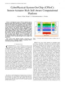
alphanumeric value, some convention is required to render the information computerinterpretable. Therefore, using non-standard, user-defined object type definitions for mapping CPS-related information into the IFC schema may be problematic and error-prone. Property sets, representing a generic approach towards describing object properties based on key-value pairs, allow attaching additional data to IFC entities. For property sets, predefined keys (and corresponding data types for the values) are defined in the IFC standard, while userdefined key-value pairs may be part of an IFC model instance as well. However, similar to user-defined object type definitions, non-standard IFC properties may be problematic for mapping CPS-related information into the IFC schema due to their indefinite keywords. In summary, CPS-related information can partially be represented with proxy elements, object type definitions, and property sets. However, such partial representation of CPS-related information may cause a semantic loss of information. Consequently, an explicit IFC extension is introduced in the following subsection for mapping CPS-related information into the IFC schema in a standardized manner. 3.2 CPS-related extension of the IFC schema The IFC extension proposed in this study comprises a definition of new entities and a specification of attributes relevant to the CPS-related information to be mapped. An extract of the IFC schema extension is presented in Figure 2. Exemplarily, three entities added to the IFC schema are illuminated in more detail. These entities, in Figure 2 gray-colored, are sensor nodes (IfcSensorNode), sensor networks (IfcSensorNetwork), and structural health monitoring and control systems (IfcMonitoringControlSystem) within a CPS. The entities are integrated into the inheritance tree of the existing IFC schema according to their semantic meaning. Sensor nodes As can be seen from Figure 2, sensor nodes, represented by IfcSensorNode entities, are considered objects (IfcObject) or, more precisely, products (IfcProduct). A product according to the IFC standard is an abstract representation of any object that appears in a geometric or spatial context. Thus, the IfcProduct entity is assigned with a geometric representation and a location. Furthermore, references to other IfcProduct entities may be mapped, such as the relation between a sensor node and the structural elements being monitored. Taking a closer look at the IFC inheritance tree, a sensor node is an AEC (architecture, engineering, and construction) product, represented by the abstract entity IfcElement. Among other functionalities, an IfcElement entity may be connected to other IFC elements, e.g. to logically represent the network connection between sensor nodes. A sensor node is an element of a distributed system, represented by the entity IfcDistributionElement. Distributed elements may be assigned with a port (IfcPort) via the objectified relationship IfcRelConnectsPortToElement. A port provides means for an element to connect to other elements. Therewith, a physical representation of a connection, such as a tethered connection, can be mapped. With the subtype IfcDistributionPort, the flow direction of the port is mapped, indicating whether a port is a sink, a source, or both. Since sensor nodes are used to control other elements of a distributed system, the entity IfcDistributionControlElement is used as base entity for the IfcSensorNode entity. As introduced in the CPS semantic model, a sensor node integrates several components (sensors, actuators, and other resources). Therefore, inherited from the abstract IfcObjectDefinition entity shown in Figure 2, an aggregation between a sensor node and the sensor node components is represented using the objectified IfcRelAggregates relationship entity. In 5
particular, sensors represented by the entity IfcSensor and actuators represented by the entity IfcActuator may be part of a sensor node. Through object type definitions, IfcSensor entities may be specialized to specific sensor types. However, the current IFC schema does not provide predefined enumerators to describe all sensor types typically deployed in cyber-physical systems. Therefore, additional enumerators are added to the IFC schema, e.g. for representing sensor information related to accelerometers and stain gauges. Furthermore, additional predefined property sets are added to the sensor types that are not available in the current IFC schema. Besides sensors and actuators, other IfcProduct entities for the power supply and the communication unit are part of a sensor node. For example, a battery is represented by the entity IfcElectricFlowStorageDevice (predefined object type: BATTERY) and an antenna is represented using the entity IfcCommunicationsAppliance (predefined object type: ANTENNA).
Figure 2: Extract of the CPS-related extension of the IFC schema with new IFC entities gray-colored.
Sensor networks A sensor network (IfcSensorNetwork), according to the CPS semantic model, is a collection of nodes, e.g. sensor nodes and base stations. In this sense, a sensor network is a distinct aggregation of nodes under topological, non-geometrical grouping aspects represented in the IFC schema through the IfcGroup entity, as illustrated in Figure 2. Furthermore, a sensor network shows characteristics of a system (IfcSystem), which is a subtype of a group. A 6
system is an organized combination of related parts, composed for a common purpose to provide a certain service. Here, the system’s grouping aspect derived from the IfcGroup entity can be interpreted as a functionally related aggregation of the nodes assembled in the system. The relation between the sensor nodes and the sensor network is mapped by an IfcRelAssignsToGroup relationship object. Last but not least, an IfcSystem entity assigns the system to spatial structure entities, such as sites, buildings, stories, spaces, or spatial zones. Structural health monitoring and control systems A structural health monitoring and control system (IfcMonitoringControlSystem), being part of a CPS, is a functionally related aggregation of entities. Here, the SHM and control system is grouped by the sensor network(s) it includes and the computer system. In the IFC schema, a computer device may be represented with the entity IfcCommunicationsAppliance (predefined object type: COMPUTER), while a sensor network is represented with the entity IfcSensorNetwork. In this study, a schema file representing the IFC schema extension is developed based on the EXPRESS standard (ISO 10303-11, 2004). EXPRESS is a data modeling language for product data related to a specific domain of interest, e.g. for the automotive, the aeronautic, or the building industry. The proposed schema file as well as the IFC model instance developed in the following sections, based on the extended IFC schema, are formally verified using professional checking tools (Apstex, 2017). The checking tools applied for verification are also used for the official certification of IFC interfaces of commercial BIM software tools (b-Cert, 2017). 4. BIM-based modeling and implementation of a cyber-physical system To validate the BIM-based CPS modeling approach in laboratory experiments, a CPS prototype is designed and implemented for structural health monitoring and control. The CPS prototype consists of a four-story laboratory shear frame structure equipped with a wireless structural health monitoring and control system. The SHM and control system is composed of wireless sensor nodes capable of local data processing and automated decision making with respect to damage (“virtual actuation”). As shown in Figure 3, each story of the structure is a rectangular 300 mm × 200 mm (length × width) aluminum plate fixed to four aluminum columns of 20 mm × 2 mm rectangular cross sections. The weak sides of the column cross sections (i.e. the shorter sides) are aligned with the length of the plate. The height of each story is 300 mm. The BIM-based model of the CPS prototype, shown in Figure 3, consists of the structural system and the structural health monitoring and control system (i.e. wireless sensor nodes). Clearly, modeling the CPS prototype with conventional IFC-compliant BIM software tools would not be possible, because the proposed CPS-related extension of the IFC schema is not fully supported by conventional BIM software tools – only the structural system can be modeled with conventional BIM software tools. Therefore, upon BIM-based modeling of the structural system, the IFC model instance of the structural system is exported as an IFC file. In the IFC file, specific CPS-related information about the structural health monitoring and control system, which cannot be modeled using conventional BIM software tools, is added, achieving a full BIM model of the CPS prototype. The IFC file can advantageously be used to document and to archive CPS-related information in compliance with the IFC standard. Upon BIM-based modeling, the CPS prototype is physically implemented to validate the proposed IFC extension in laboratory experiments (Figure 4). The wireless sensor nodes of the CPS prototype are of type Oracle SunSPOT (Oracle, 2010). The SunSPOT sensor nodes 7
are equipped with a Java-programmable 400 MHz ARM microprocessor, 512 kB RAM, and 4 MB flash memory. Wireless communication is achieved via an IEEE 802.15.4 radio transceiver using the ZigBee protocol. The sensing board includes a digital output accelerometer, a temperature sensor, and a light sensor. The accelerometer used in this study is of type MMA7455L, and it is able to sample up to 250 Hz, with selectable measurement ranges of ±2 g, ±6 g, or ±8 g.
Figure 3: BIM-based model of the CPS prototype.
Figure 4: Physical implementation of the CPS prototype.
Automated damage detection is implemented into the sensor nodes. The automated damage detection involves local data processing and information exchange among the sensor nodes for extracting the mode shapes of the test structure through frequency domain decomposition (Brincker et al., 2000). Local data processing essentially comprises collecting acceleration response measurements and transforming the collected data into the frequency domain via a fast Fourier transform algorithm embedded into the sensor nodes. For details on the embedded damage detection approach, the interested reader is referred to Smarsly & Law (2013) and Smarsly & Petryna (2014). Two laboratory tests are performed on the CPS prototype, one with the initial structural state of the structure and one after introducing damage to the structure by loosening the column-to-plate connections on one side of the structure. The damage is reflected on the Fourier transforms of acceleration response data, as calculated by the wireless sensor nodes deployed (Figure 5). From Figure 5, it is clear that the introduced damage results in a migration of the peaks in the Fourier spectrum towards lower frequencies, i.e. the structure becomes more flexible in the damaged state. In the damaged state, the frequency is notably lower than in the undamaged structural state, while low deviations are also observed in the corresponding mode shape. As a result of the differences in the identified fundamental frequency and the extracted mode shape, the sensor nodes, through its “virtual” actuators, transmit a damage detection alert signal to the base station.
8
Figure 5. Comparison between Fourier spectra of the initial structural state and the damaged structural state for story 3.
5. Summary and conclusions In this study, a novel BIM-based modeling approach for cyber-physical systems has been presented and validated in laboratory experiments. Focusing on CPS applications for structural health monitoring and control, an extension of the current IFC schema has been proposed to represent CPS-related information, enabling BIM-based modeling of cyberphysical systems in compliance with the IFC standard. The IFC schema extension has been developed based on a CPS semantic model, which serves as a technology-independent metamodel to formally describe cyber-physical systems deployed in structural health monitoring and control applications. To validate the BIM-based CPS modeling approach, a CPS prototype has been designed, implemented and tested in laboratory experiments. As a result, it is concluded that BIM-based CPS modeling in compliance with the IFC standard facilitates the design process, the documentation, and the information exchange of cyberphysical systems. Acknowledgments The authors would like to gratefully acknowledge the financial support provided by the German Research Foundation (DFG) through grant numbers SM 281/7-1 and GRK 1462. Any opinions, findings, conclusions, or recommendations expressed in this paper are solely those of the authors and do not necessarily reflect the views of DFG or any other organizations and collaborators. References Apstex (2017). IFC Tools Project. Online: http://www.apstex.com, accessed: 2017-04-12. Atkins, E.M. & Bradley, J.M. (2013). Aerospace cyber-physical systems education. In: The American Institute of Aeronautics and Astronautics Infotech Aerospace Conference, 2013, Boston, MA, USA. b-Cert (2017). The official platform for the buildingSMART IFC4 certification. Online: http://www.b-cert.org, accessed: 2017-04-12. Bhuiyan, M. Z. A., Wu, J., Wang, G., Cao, J. & Jiang, W. (2016). Sensing and Decision Making in Cyber-Physical Systems: The Case of Structural Event Monitoring, IEEE Transactions on Industrial Informatics 12(6), pp. 2103-2114. Bilek, J., Mittrup, I., Smarsly, K. & Hartmann, D. (2003). Agent-based Concepts for the Holistic Modeling of Concurrent Processes in Structural Engineering. In: Proc. of the 10th ISPE International Conference on Concurrent Engineering: Research and Applications. Madeira, Portugal, July 26, 2003. Brincker, R., Andersen, P. & Zhang, L. (2000). Modal identification from ambient responses using frequency domain decomposition”. In: Proc. of the 18th International Modal Analysis Conference. San Antonio, TX, USA, 07/02/2000.
9
BuildingSMART (2017). IFC Infrastructure Room. Online: http://www.buildingsmart-tech.org/infrastructure, accessed: 2017-04-12. Casciati, S. & Chen, Z. C. (2012). An active mass damper system for structural control using real-time wireless sensors, Structural Control and Health Monitoring 19(8), pp. 758-767. Dragos, K. & Smarsly, K. (2015). A Comparative Review of Wireless Sensor Nodes for Structural Health Monitoring. In: Proc. of the 7th International Conference on Structural Health Monitoring of Intelligent Infrastructure. Turin, Italy, 07/01/2015. Hackmann, G., Guo, W., Yan, G., Sun, Z., Lu, C. & Dyke, S. (2014). Cyber-physical co-design of distributed structural health monitoring with wireless sensor networks, IEEE Transactions on Parallel and Distributed Systems 25(1), pp. 63-72. Huang, H.-M., Tidwell, T., Gill, C., Lu, C., Gao, X. & Dyke, S. (2010). Cyber-physical systems for real-time hybrid structural testing: A case study. In: Proc. of the International Conference on Cyber-Physical Systems. Stockholm, Sweden, 04/14/2014. ISO 10303-11 (2004). Industrial automation systems and integration - Product data representation and exchange – Part 11: Description methods: The EXPRESS language reference manual. ISO 16739 (2013). Industry Foundation Classes (IFC) for data sharing in the construction and facility managem. industries. Legatiuk, D., Dragos, K. & Smarsly, K. (2017). Modeling and evaluation of cyber-physical systems in civil engineering. In: Proc. of the 88th Annual Meeting of the International Association of Applied Mathematics and Mechanics, March 6, 2017, Weimar, Germany. Oracle Corp. (2010). Sun SPOT eDEMO Technical Datasheet, 8th edition. Sun Labs,Santa Clara, CA, USA, 2010. Sampigethaya, C. & Poovendran, R. (2013). Aviation Cyber–Physical Systems: Foundations for Future Aircraft and Air Transport, Proc. of the IEEE 101(8), pp. 1834-1855. Sanfelice, R.G. (2016). Analysis and design of cyber-physical systems: a hybrid control systems approach. In: Rawat D.B. and Rodriguez J.J.P.C. (eds.). Cyber-physical systems: From theory to practice, Boca Raton, FL, USA: CRC Press (Taylor & Francis Group), pp. 3-31. Smarsly, K. (2013). Agricultural ecosystem monitoring based on autonomous sensor systems. In: Center for Spatial Information Science and Systems, George Mason University. In: Proc. of the Second International Conference on Agro-Geoinformatics 2013. Fairfax, VA, USA, August 12, 2013. Smarsly, K. & Hartmann, D. (2009a). Multi-scale monitoring of wind energy plants based on agent technology. In: Proc. of the 7th International Workshop on Structural Health Monitoring. Stanford, CA, USA, 09/09/2009. Smarsly, K. & Hartmann, D. (2009b). Real-time monitoring of wind energy converters based on software agents. In: Proc. of the 18th International Conference on the Applications of Computer Science and Mathematics in Architecture and Civil Engineering. Weimar, Germany, 07/07/2009. Smarsly, K., Hartmann, D. & Law, K. H. (2012). Structural Health Monitoring of Wind Turbines Observed by Autonomous Software Components – 2nd Level Monitoring. In: Proc. of the International Conference on Computing in Civil and Building Engineering. Moscow, Russia, 06/27/2012. Smarsly, K., Hartmann, D. & Law, K. H. (2013). A Computational Framework for Life-Cycle Management of Wind Turbines incorporating Structural Health Monitoring. Structural Health Monitoring – An International Journal, 12(4), pp. 359-376 Smarsly, K. & Law, K. H. (2013). Advanced Structural Health Monitoring based on Multi-Agent Technology. In: Zander, J. & Mostermann, P. (eds.). Computation for Humanity: Information Technology to Advance Society. Pp. 95-126. Boca Raton, FL, USA: CRC Press – Taylor & Francis Group, LLC. Smarsly, K., Law, K. H. & Hartmann, D. (2012). Towards Life-Cycle Management of Wind Turbines based on Structural Health Monitoring. In: Proc. of the 1st International Conference on Performance-Based Life-Cycle Structural Engineering. Hong Kong, China, 12/05/2012. Smarsly, K., Lehner, K. & Hartmann, D. (2007). Structural Health Monitoring based on Artificial Intelligence Techniques. In: Proc. of the Intern. Workshop on Computing in Civil Engineering. Pittsburgh, PA, USA, 07/24/2007. Smarsly, K. & Petryna, Y. (2014). A Decentralized Approach towards Autonomous Fault Detection in Wireless Structural Health Monitoring Systems. In: Proc. of the 7th European Workshop on Structural Health Monitoring. Nantes, France, 07/08/2014. Smarsly, K. & Tauscher, E. (2016). Monitoring information modeling for semantic mapping of structural health monitoring systems. In: Proc. of the 16th International Conference on Computing in Civil and Building Engineering. Osaka, Japan, 07/06/2016. Yuan, X., Anumba, C. J. & Parfitt, M. K. (2016). Cyber-physical systems for temporary structure monitoring, Automation in Construction 66(2016), pp. 1-14.
10