Available online at www.sciencedirect.com
Procedia Engineering 14 (2011) 1037–1042
The Twelfth East Asia-Pacific Conference on Structural Engineering and Construction
IFC Extension for Road Structures and Digital Modeling S.-H. LEE*, B.-G. KIM Department of Civil and Environmental Engineering, Yonsei University, Seoul, Korea
Abstract This paper introduces an information modeling technique for road structures which include roads, bridges and tunnels. The Industry Foundation Classes (IFC) of BuildingSMART, which has become a de-jure standard for exchange of the Building Information Modeling (BIM) data in the AEC industry, was employed to develop a data model. Spatial and physical components of the road structures were identified and added into the IFC in order to capture the semantics of shape objects in a 3-D model. This paper also demonstrates how the structural components are hierarchically aggregated in digital modeling of road structures.
© 2011 Published by Elsevier Ltd. Open access under CC BY-NC-ND license. Selection Keywords: BIM, data model, IFC, road structures
1. Introduction The building information modeling (BIM) is an emerging technology providing a comprehensive framework for building of integrated information environment in construction project. It generally uses 3D based and object-oriented modeling tools. The interoperability of the model data is also a major concern in the BIM technology. The Industry Foundation Classes (IFC) developed by buildingSMART (Liebich et al. 2010) is becoming a de-jure standard supported by commercial BIM tools for building structures. The information modeling techniques and operation strategies for other civil infrastructures, however, are still at an early development stage. Most available techniques are limited to specific software packages. The LandXML (Crews et al. 2002) is an open standard format supported by several commercial programs such as GIS applications and CAD based applications used in roadway projects. The LandXML,
* Corresponding author and Presenter Email:
[email protected]
1877–7058 © 2011 Published by Elsevier Ltd. Open access under CC BY-NC-ND license. doi:10.1016/j.proeng.2011.07.130
1038
S.-H. LEE and B.-G. KIM / Procedia Engineering 14 (2011) 1037–1042
however, cannot represent details of structural information of bridge and tunnels. In order to represent the structural details of the road structures, a product data model can be used. STEP based bridge information model (Lee and Jeong 2006) and IFC bridge model V2 R7 (Arthaud and Lebegue 2007) are the examples. However, these product data models have several limitations: 1) Previous models only focus on bridge among road structures; 2) Bridge span and sub-spaces of transversal direction on longitudinal direction of bridge cannot be represented; 3) Curvilinear features of spatial characteristics of roadway (e.g., reference points for start and end, and bridge length, etc.) cannot be represented; 4) While ISO 6707-1 (ISO TC59/SC2, 2004) classifies substructure elements (e.g., pier, abutment, and pylon) as physical elements, Arthaud and Lebegue (2007) classified them as spatial elements; and 5) Common elements or facilities (e.g., pavement, barrier, and curb), which are installed as typical road elements, did not identified. This study extends the BIM technology for road structures. Information modeling of road structures, in this study, refers to an activity of drawing and identifying physical and spatial components of road structures in a 3-D model space, and assigning property data to corresponding physical or spatial components of the 3-D model. Information model refers to a data schema that can be used to manipulate the model data with computer memory, databases, and files. This study employed the IFC to develop an information model for road structures because it provides well organized kernel and contains rich information objects used in construction industry. 2. IFC Extension for Road Structures The IFC categorizes construction components into two types: spatial element and physical element. ‘IfcSpatialElement’ and ‘IfcElement’ in the IFC represent the spatial and physical elements, respectively. On the basis of the IFC framework, major construction components of road structures are added into the IFC as shown in Table 1. Table 1: Extension entities for structural components of road structures Category
Entities of abstract super
Entities of common components
Entities of domain components
IfcRoadSpatialElement
IfcRoadSite, IfcLane
IfcBridge, IfcBridgeSpan, IfcTunnel,
(below IfcSpatialElement)
IfcCivilSpatialProxy,
IfcTunnelSpace, IfcSlope
type Spatial elements
(for road, bridge, tunnel)
IfcRoadJunction Physical
IfcRoadServiceElement
IfcRoadBarrier,
IfcInspectionLadder,
elements
(below IfcElement)
IfcRoadSignalPost,
IfcRoadStair, IfcBridgeInspectionDeck
IfcTrafficSignal, IfcPost, IfcRoadRailing, IfcCrashCushion IfcRoadElement
IfcPavementLayer, IfcCurb,
(below IfcElement)
IfcGutter, IfcSegment,
IfcRoadBedLayer, IfcDrainageModel, IfcEmbankment,
IfcRetainingWall
IfcBridgeMember, IfcBridgeCable, IfcExpansionJoint, IfcBearingSupport, IfcBridgeAbutment, IfcBridgePier, IfcFoundation, IfcPylon, IfcBridgeSlab, IfcCivilFooting, IfcCivilPile, IfcCivilCaisson, IfcTunnelLining
Part components
-
-
IfcBridgeElementPart, IfcGroundReinforcingElement,
1039
S.-H. LEE and B.-G. KIM / Procedia Engineering 14 (2011) 1037–1042
IfcMemberConnector (below IfcElementComponents) Group
IfcRoadSystem
IfcRoadSignalSystem,
(below IfcGroup)
IfcInspectionSystem, IfcBridgeSytem,
One of major differences between the developed model and previous IFC bridge model is the enrichment of spatial elements. Two entities, ‘IfcLane’ and ‘IfcBridgeSpan’, were added for overcoming limitations of previous product data models. ‘IfcLane’ divides transversal spaces of roadway, and ‘IfcBridgeSpan’ represents a spatial container of a bridge span. ‘IfcBridge’, ‘IfcRoad’, and IfcTunnel’ are spatial elements representing each structure type in road network. In order to define common properties and line oriented feature for each spatial road elements, ‘IfcRoadSpatialElement’ was developed as an abstract super type of the other spatial elements. A main characteristic of the element is that it can represent a curvilinear feature of road structures. This is distinguished from spot oriented feature of building structures. While the ‘IfcSite’ in the original IFC can only represent one reference point, the new spatial element enables other spatial elements to represent the both of start and end reference points, directly. The new physical elements are categorized into 4 groups: Roads, Bridges, Tunnels, and Facilities. Most entities in previous IFC are able to represent some structural members of road structures. For example, ‘IfcBeam’, ‘IfcColumn’, and ‘IfcSlab’ can represent some parts of bridge members. The designed volume resulted by earth work can be also represented with ‘IfcGeographicElement’. However, definitions of IFC specification are not enough to represent the concept of structural member in terms of bridge and tunnel engineering. In addition, sustainability and reusability of existing parsers in commercial software must be major concerns when a new definition on specific entity is made. Hence, in this study, two new elements, ‘IfcRoadElement’ and ‘IfcRoadServiceElement’ were added below the ‘IfcElement’ for representing physical components of road structures and facilities installed in a specific spatial element of a road structure. The ‘IfcRoadServiceElement’ is an abstract type of facilities installed in road structures, and ‘IfcRoadElement’ denotes an abstract type of the other structural components of road, bridge, and tunnel. The ‘IfcBridgeElementPart’ represents sub-parts of structural member such as flange, web, stiffener, diaphragm, and rib, and it was derived from the IFC bridge model. A new entity for road structures, ‘IfcGroundReinforcingElement’, can represent reinforcing elements for ground, such as rock-bolt, steel rib for NATM tunnel, and earth anchor while the ‘IfcReinforcingElement’ of the IFC only represents steel elements reinforcing concrete members. The other entity, ‘IfcBridgeMemeberConnector’ refers to a joint system which is aggregated with other accessories and fasteners provided in the IFC. This entity enables us to define repeated and complex joint systems such as splice and cable anchorage with a type entity representing the joint system. 3. Digital Modeling of Road Structures Authors have provided a methodology for developing 3-D information modeling tool (Lee et al. 2005). The modeling tool has been developed on the AutoCAD platform because the AutoCAD is one of the major CAD tools widely used in the construction industry. In order to manipulate 3-D model data illustrated in chapter 2, the modeling tool was modified in this study. The new entities can be hierarchically represented by using the ‘IfcRelAggregates’ provided in the IFC. Figure 1 illustrates an example for the aggregations of spatial elements of road. Building mechanism of hierarchical structures for physical component and part element is the same with that for spatial
1040
S.-H. LEE and B.-G. KIM / Procedia Engineering 14 (2011) 1037–1042
elements. As another new entity, ‘IfcRelCivilSpatialElementBoundary’ was added to capture boundaries among spatial elements of road structures because the ‘IfcRelSpaceBoundary’ of the IFC link only ‘IfcSpace’ that refers to a space in a building storey. Figure 2 depicts how to build relationship between a spatial element and physical elements. Aggregation of spatial element for longitudinal direction IfcRoad
Aggregation of spatial element for longitudinal direction (shared entity for road, tunnel, bridge)
(COMPLEX) IfcRelAggregates
If cRelAggregates
(UNIT)
(UNIT)
(UNIT)
IfcRoad
IfcRoad
If cRelAggregates
If cRelAggregates
(UNIT)
IfcLane
IfcLane
If cRelAggregates
(PARTIAL)
(PARTIAL)
IfcLane (PARTIAL) IfcRoad
IfcRoad
IfcLane
IfcRoad
IfcRoad
(PARTIAL)
(PARTIAL) (PARTIAL)
IfcRelCivilSpatial ElementBoundary
Figure 1: Example of spatial element aggregation for road
IfcRoad (Partial/Unit/Complex) IfcRelContainedIn SpatialStructure IfcCurb
IfcDrainage Mole
IfcBarrier (Median strip)
IfcGutter (L-type)
Figure 2: Relationship between spatial element and physical element
IfcPavementLayer
IfcRoad BedLayer
IfcGutter (U-type)
1041
S.-H. LEE and B.-G. KIM / Procedia Engineering 14 (2011) 1037–1042
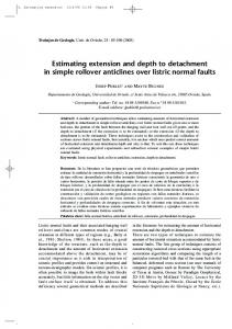
Figure 3 illustrates examples of information modeling for a complex type of road section that includes bridge and tunnel sections. The total length of modeling section is 1.1 km and it includes two bridges and one NATM (New Austrian Tunneling Method) tunnel. Since road components generally follow road path, swept solid model and extrude solid model are mainly used to represent the road, tunnel and bridge components. Line entities in Figure 3 (a) represent longitudinal regions for each road structure. Each line entity represents basic geometric shape of curvilinear feature of each road structure (i.e. road, bridge, and tunnel). The PSC box girder shown in Figure 3 (a) illustrates the ‘IfcBridgeMember’ and ‘IfcSegment’. The ‘IfcSegment’ defined in this study represents a generic component denoting prismatic member of bride as well as a specific segment of other physical member such as tunnel segment, block of retaining wall, and segment of pylon. Figure 3 (b) shows an example of allocation for spatial element of tunnel. The partial type of tunnel represents detail tunnel sections that have different reinforcing patterns for different rock types. The shared physical element of road structures such as ‘IfcBarrier’, ‘IfcPavementLayer’, and ‘IfcRetainingWall’ are shown in Figure 3 (c).
IfcGround ReinforcingElement (SteelRib)
Section Profile for IfcSegment IfcBridgeMember (PSC Box Girder)
IfcSegment
IfcGround ReinforcingElement (RockBolt)
IfcTunnel (Complex Type)
IfcRelAggregate
IfcRoad
IfcTunnel (Unit Type)
IfcTunnel (Partial Type)
IfcBridge (Complex Type)
(a) example of bridge model
(b) example of tunnel model IfcGround ReinforcingElement (RockBolt)
IfcTunnel (Complex Type)
IfcPavementLayer
IfcTunnelLining IfcBarrier IfcBridgeMember
(c) example of integrated model Figure 3: Examples of digital modeling for a complex road project
IfcTunnel (Unit Type)
1042
S.-H. LEE and B.-G. KIM / Procedia Engineering 14 (2011) 1037–1042
4. Conclusions This paper provided a 3-D information modeling technique for road structures such as roads, bridges, and tunnels. It has been shown that information modeling technique enables engineers to build and identify spatial and physical components of road structures with a 3-D digital model, hierarchically. In order to capture and manipulate the model data, this study employed a road information model using the IFC resources. Examples shown in this paper reveal that the structured data set can present an integrated component hierarchy of 3-D objects in a complex 3-D road model including road, bridge, and tunnel. Acknowledgments We gratefully acknowledge the support of the Center for Future Infrastructure System in Yonsei University, a Brain Korea 21 program. References [1]
Arthaud G and Lebegue E (2007). IFC-Bridge V2 data model-Edition R7. BuildingSMART.
[2]
Crews N, Hall E, and Rebolj D (2002). LandXML Schema Version 1.0 Reference. LandXML.org.
[3]
ISO TC59/SC2 (2004). ISO 6707-1: 2004 Building and civil engineering – Vocabulary – Part1: General terms. International
[4]
Lee S-H and Jeong Y-S (2006). A system integration framework through development of ISO 10303-based product model
[5]
Lee S-H, Kim B-G, and Jeong Y-S (2005). Construction of integrated engineering database for lifetime management of
Organization for Standardization. for steel bridges. Automation in Construction. 15(2). pp. 212-228. bridges on road network. Proceedings of the International Workshop on Lifetime Engineering of Civil Infrastructure, Ube, Japan, pp. 31-55. [6]
Liebich T, Adachi Y, Forester J, Hyvarinen J, Richter S, Chipman T, Weise M., and Wix J (2010). Industry Foundation Classes IFC2xEdition4 Release Candidate 1. BuildingSMART.