image planes are parallel to each other and the epipoles ... its corresponding point (x', y', f)T E I', ... their corresponding points in the current image, namely.
Proceedingsof the 1999 IEEE International Conference on Robotics & Automation Detroit, Michigan May 1999
Image-Based Robot Navigation Under the Perspective Model Ronen Basri* Ehud Rivlin Ilan Shimshonit Dept. of Computer Science Dept. of Ind. Eng. and Mgmt. Dept. of Applied Math The Weizmann Inst. of Science The Technion The Technion Rehovot 76100 Israel Haifa 32000 Israel Haifa 32000 Israel Abstract In a recent paper we have presented a method for image-based navigation by which a robot can navigate to desired positions and orientations in 3 - 0 space specified b y single images taken from these positions. In this paper we further investigate the method and develop robust algorithms for navigation assuming the perspective projection model. In particular, we develop a tracking algorithm that exploits our knowledge of the motion performed by the robot at every step. This algorithm allows us to maintain correspondences between frames and eliminate false correspondences. We combine this tracking algorithm with an iterative optimization procedure to accurately recover the displacement of the robot from the target. Our method for navigation is attractive since at does not require a 3 - 0 model of the environment. We demonstrate the robustness of our method by applying it to a six degree of freedom robot arm.
1
Introduction
In a recent paper [l] we proposed an approach to the problem of guiding a robot to desired positions and orientations in space. In this method the target pose is specified by an image taken from that pose (the target image). The task given to the robot is to move to a position where an image taken by a camera mounted on the robot will be identical to the target image. During the execution of this task the robot is allowed to take pictures of the environment, compare them with the target image, and use the result of this comparison to determine its subsequent steps. This method is attractive since it requires no advance measurement of the environment. Only the target image is given to the robot as an input. In this paper we further investigate the *This research was supported in part by the Israeli Ministry of Science, Grant No. 9766. Ronen Basri is a n incumbent of Arye Dissentshik Career Development Chair at the Weizmann Institute. t Ilan Shimshoni is supported in part by the Goldschmidt Foundation, and is a David and Ruth Moskowitz Academic Lecturer.
0-7803-5180-0-5/99$10.00 0 1999 IEEE
method and focus on constructing robust algorithms to perform navigation under perspective projection. Our method can be compared to studies such as [lo, 81 in which the path of the robot is predetermined, and a pre-storage of the entire path is needed. This is particularly problematic if the starting position of the robot may vary. “On-line” methods (e.g [3]) exist, but are commonly limited to the 2-D plane, or need the storage of a 3-D model of the environment (e.g [2, 41). Also of relevance is work on image-based visual servoing (see reviews in [7, 61). Below we present a method for visual navigation under the perspective imaging model. In our method the robot is instructed to reach a desired pose specified by a single image taken from that pose. The method then proceeds by comparing the target image to images taken by the robot as it moves toward the target. At every steps pairs of corresponding feature points are found and used to estimate the remaining displacement. of the robot to the target position. A robust tracking technique that exploits our knowledge of the motion performed by the robot between frames is developed, and an iterative, least-square estimation is used to accurately determine the target position and orientat,ion. These algorithms enable us to maintain correspondences throughout the frames and eliminate false matches. This is important in order to obtain a fast and efficient convergence to the desired pose. Our navigation method is attractive for several reasons. The method does not require a 3-D model of the environment. The path taken by the robot is not determined in advance. Its starting position is allowed to vary as long that the initial and target images contain sufficiently many correspondences to determine the displacement between the corresponding positions. Furthermore, the path determined at every step is almost independent of the previous steps taken by the robot. Because of this property the robot may be able, while moving toward the target, to perform auxiliary tasks or to avoid obstacles, without this impairing its ability to converge to the target position. Finally, by using visual
2578
feedback the robot can overcome motion calibration errors. Applications to our method exist in almost every domain of robot navigation and manipulation. In addition, the method offers a convenient and natural relay for human-robot interface. The paper is divided as follows. Section 2 reviews the principles of our navigation method under the perspective projection model. Section 3 introduces our tracking method and the iterative solution for the pose problem. Experimental results are shown in Section 4.
2
Perspective visual navigation
In this section we review the principles of our navigation method under perspective projection. Additional details can be found in [l].We wish to move a robot to an unknown target position and orientation SIwhich is specified by an image I taken from that position. Denote the current unknown position of the robot by our goal then is to lead the robot to S. Below we assume that the internal parameters of the camera are all known. The external parameters, that is, the relative position and orientation of the camera in these pictures, is unknown in advance. To determine the motion of the robot we would like to recover the relative position and orientation of the robot S’ relative to the target pose S. Given a target image I taken from S and given a second image 1’ taken from S’ by finding sufficiently many correspondences in the two images we may estimate the motion parameters separating the two images using the algorithm described in [5, 121, This algorithm requires at least eight correspondences in the two images. The algorithm proceeds by first recovering the essential matrix E relating corresponding points in the two images. Once the essential matrix is recovered, it can be decomposed into a product of two matrices E = RT, the rotation matrix R and a matrix T which contains the translation components. The rotation matrix, which determines the orientation differences between the two images, can be fully recovered. The translation components, in contrast, can be recovered only up to an unknown scale factor. These recovered translation components determine the position of the epipole in the current image, which indicates the direction to the target position. In Section 2.1 below we show how to determine whether the target position is in front or behind the current position of the robot. However, the distance to the target position cannot be determined from two images only. Note that in the presence of noise this procedure does not guarantee that the recovered matrix R would in fact represent a rotation. In Section 3 we outline an iterative, non-linear minimization procedure
s‘,
to compute the rigid displacement of the robot from the target. In our experiments we use the recovered rotation and translation as a starting point for this procedure.
2.1
Resolving the ambiguity in the direction to the target
Using the current and target images we have completely recovered the rotation matrix relating the two images. Since a rotation of the camera is not affected by depth we may apply this rotation to the current image to obtain an image that is related to the target image by a pure translation. After applying this rotation the two image planes are parallel to each other and the epipoles in the two images fall exactly in the same position. Denote this position by (vz , vy, f)T. We may now further rotate the two image planes so as to bring both epipoles to the position ( O , O , f)T. Denote this rotation by Ro. Notice that there are many different rotations that can bring the epipoles to ( O , O , f)T,all of which are related by a rotation about ( O , O , f ) T . For our purpose it will not matter which of these rotations is selected. After applying Ro to the two images we now have the two image planes parallel to each other and orthogonal to the translation vector. The translation between the two images, therefore, is entirely along the optical axis. Denote the rotated target image by I and the rotated current image by 1’. Relative to the rotated target image denote an object point by P = (XIY, 2 ) . Its coordinates in I are given by x = f X / Z , y = f Y / Z and its corresponding point (x’,y’, f)T E I’,
t represents the magnitude of translation along the optical axis (so It1 = ~ ~ ( t z , t y , t zand ) ~ [its) ,sign is positive if the current position is in front of the target position, and negative if the current position is behind the target position. We can therefore resolve the ambiguity in the direction by recovering the sign o f t . To do so we divide the coordinates of the points in the target image with their corresponding points in the current image, namely 2 2‘
-
y --Z + t
y’
z
t =1+-. Z
This implies that t = Z(x/x’ - 1). Unfortunately, the magnitude of Z is unknown. Thus, we cannot fully recover t from two images. However, its sign can be determined since
2579
sign(t) = sign(2)si&
- 1). 2’
(3)
Notice that since we have applied a rotation to the target image Z is no longer guaranteed to be positive. However, we can determine its sign since we know the rotation Bo?and so we can determine for every image point whether it moved to behind the camera as a result of this rotation. Finally, the sign of x/x’ - 1 can be inferred directly from the data, thus the sign o f t can be recovered. The sign of t is determined by the sign computed by The majority of pairs of points.
2.2
Recovering the distance to the target
Computing the distance to the target is important in order to perform smooth motion in which the robot gradually translates and rotates in the same rate toward the target position and orientation. Such a gradual motion is important particularly in order to roughly maintain the same part of the scene visible throughout the motion. Unfortunately, the distance to the target cannot be determined by comparing a single image acquired by the robot to the target image. Instead, we let the robot move one step and take a second image. We then use the changes in the position of feature points due to this motion to recover the distance. Using the current and target images we have completely recovered the rotation matrix relating the two images. Since a rotation of the camera is not affected by depth we may apply this rotation to the current image to obtain an image that is related to the target image by a pure translation. Below we refer by I’ and I” to the current and previous images taken by the robot after rotation is compensated for so that the image planes in I , I’, and I” are all parallel. Given a point p = (x,y, f)T E I , suppose the direction from the current image I’ to the target position is given by t = (tz,t,,t,)T, and that between the previous image I” and the current image the robot performed a step at in that direction. Denote by n the remaining number of steps of size at separating the current position from the target (so that n = l / a ) . The x coordinate of a point in the target, current, and previous images are
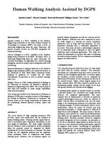
Figure 1: Geometric interpretation of the cross-ratio . of the point along the epipolar line in the three images. (Thus, n is obtained as a cross-ratio along this line.) The computation of the distance can be interpreted geometrically as follows. Consider Figure 1. Given three images whose centers of projection 0,O’ and 0” lie along a straight line leading to a point at infinity V,. The number of steps to the target is given by the cross-ratio of these four points. However, the positions of the centers of the cameras is not given to us explicitly. Instead, for some 3D point P we have its projection in the three images from which the cross ratio in (5) has been computed. These two cross ratios, however, are the same. To see this, consider the line 1 which lies in the plane O,O’,P, is parallel to the image planes of the images, and whose distance from P is f (the focal length). Clearly, the cross-ratio obtained for the points on 1 (r,r’,r’’,rV)is the same as the cross-ratio we are seeking. As can be readily shown the shaded triangles in the figure are congruent. Consequently, the value obtained by the distances in the image from the points to the epipole yields the same cross-ratio as the value obtained for 1, which is equal to cross-ratio we are seeking. It is obvious from the figure that the cross-ratio obtained is invariant to the choice of P.
3
respectively. Eliminating X and Z and dividing by t , we obtain that (2’ - x)(t” - Vz) n= (5) (I” - d ) ( x - V,) ’ The same computation can be applied to the y coordinate of the point. In fact, we can obtain a better recovery of n if we replace the coordinates by the position
Motion recovery and tracking
When we perform visually guided navigation in the presence of extreme perspective distortions our method outlined in Section 2 may often poorly recover the relative position of the robot with respect to the target. Furthermore, maintaining correct correspondences throughout the robot’s motion may be difficult, and this may prevent the robot from converging to the target position. To improve the performance of our navigation procedure we developed and implemented two algorithms. The first algorithm recovers exactly the rotation matrix R
2580
and the epipole v given correct feature correspondences. The second algorithm tracks feature points from frame to frame exploiting our knowledge about the robot’s motion between the frames. This algorithm is used in addition to robustly estimate distance of the robot to the target. Below we describe the two algorithms.
3.1
Motion parameters estimation I
As is mentioned in the previous section, we use Hartley’s algorithm [5] to recover the essential matrix E and separate it into the rotation matrix R and the epipole v. We then use R and v as initial values for a non-linear minimization procedure that finds the R and v which minimize a least-squares error function. The error function that has to be chosen must minimize the squares of errors in values measured in the image (i.e., errors in image position). We first describe our procedure in the case that only translation separates the robot from the target. Later, we generalize the procedure to account for rotation as well. Suppose that the robot is posed such that only translation separates it from the target. In this case every pair of corresponding points is collinear with the epipole v. However, because of noise the lines connecting all pairs of corresponding points may not intersect at a single point. One way, then, to determine the epipole v is to use a linear least squares algorithm which finds the point that is closest to all the lines going through the pairs of points (see Figure 2, the dashed line represents a line through two corresponding points, p and p‘, and 1s denotes the distance of the epipole v from this line). A better measure is as follows. Given a candidate epipole v, for each pair of points compute the line through v that is closest to the two points (the solid line in Figure 2). Now, measure the distance of the points from this line ( d and d‘ in the figure), and add the square of each of these two distances to the error function. Given an epipole v and a pair of points p and p’ we find the optimal line as follows. Denote by 0 the angle between the line and the x-axis, and denote q = p - v and q’ = p‘ - v. Then
!
Figure 2: An illustration of the error function: given a pair of corresponding points p and p’ and a candidate epipole v the distance between v and the line through the two points is 1s. A better estimate is given by taking the distance from the two points and the solid line (the nearest line through v to the points). In this case the squared error value is given by d2 d 2 / .
+
In the general case when the two images are related by both rotation and translation, we first rotate one of the images by R and then compute the function described above. This measure produces suboptimal results because the errors minimized in the rotated image are of rotated points and not of the original points measured in the image. This small penalty in accuracy is the price we pay for being able to compute the closest line going through v analytically. After recovering the epipole v we can improve our estimate of the rotation matrix R. At this point we seek a matrix that satisfies the non-linear constraints RRT = I and det R = 1. For this purpose we apply a LevenbergMarquardt non-linear minimization procedure which estimates the rotation matrix R and translation vector t that bring the corresponding points to a best fit. To ensure that R satisfies the non-linear constraints we specify it using the Euler angles.
3.2
Tracking feature points
In order to recover the relative position of the robot with respect to the target it is essential to find correspondences between the images taken by the robot and the target image. In this paper we do not address the problem of finding correspondences between the initial d 2 = ( q . ( s i n O , - c o ~ 6 ) ) ~d”, = ( q ’ . ( s i n O , - ~ o s 6 ) ) ~ . image of the robot and the target image. In the experiments below (Section 4) we supplied these corresponTo find the angle ~9that minimizes d2 + dl2 we differen- dences manually. However, once the robot begins movtiate this expression by 0: ing it acquires new images, and we wish to maintain as many possible correspondences to accurately estimate ((9% q): q?))2sinecos0+ the relative displacement of the robot from the target. 2(q,q, qLqL)(cos2’6 - sin2 e) = 0. To achieve this we track feature points between frames exploiting our knowledge of the motion performed by Thus, the robot in every step. Below we describe this tracking procedure in detail. Let Ii and Ij+l denote the two images acquired by the
+
+
(si+
258 1
robot in the i’th step, and let Ri and ti denote the rotation and translation performed by the robot at this step. Given feature points in the previous image we apply the camera rotation R, to the points to obtain the new positions of the feature points in the new image had only rotation been applied between the frames. The remaining translation component of the motion between the frames causes the points to move along epipolar lines. Denote by pi the position of a feature point after applying Ri and by pj its yet unknown position in Ii+l. The epipolar line connecting pi and pj also passes through v and so can be computed. Using the computed epipolar line we choose a candidate corresponding point and by estimating robustly the distance to the target we determine which of the corresponding points is correct. To select the candidate correspondences we apply a corner detector to the new image Ii+l. Then, for every feature point pg in the rotated image we look for a corner point that lies close to pi and very close to the epipolar line through p:. The nearest point according to this criterion is selected to be a candidate corresponding feature to pi in the new image. Then, we apply Equation (5) to pj and pi, which estimates the number of steps n to the goal. For all correct matches we expect to obtain approximately the same value for n , whereas for incorrect matches we expect to obtain random values. In order to find a robust estimate for n, we look for the interval where the values are densest. This is found using a shortest-window mode estimator. I.e., the values are sorted and the middle of the window of size k which is shortest is chosen as the estimate. Once the value for n has been estimated, we have an estimate for the target position. In addition to that Equation (5) now can be inverted, and the actual position of the feature point in the new image can be computed:
x/ =
n d ’ ( 2 - v,) n(x - v,)
+ 2(2” + 2” - v,
U ‘),
.
When the computed position is far from the position found in the previous step (a false match), a corner in the vicinity of the computed position is searched for, and if such a corner is not found the computed position is used. The result of this procedure is a set of corresponding feature points in the new image. Once the corresponding features are obtained we reestimate the rotation and translation to the target position. This is important due to errors in the estimates of the relative displacement of the robot in previous steps. Denote the rotation and epipole computed in the previous step by R and v, we apply the iterative procedure described in Section 3.1 using the initial values Ri’R
and v, which are expected to be very close to the correct rotation matrix and epipole. This process of tracking and improving the estimates of the displacement of the robot is repeated at every step of the robot until the target position is reached.
4
Experimental results
In the following experiment we used an EshedRobotec ER9 six degree of freedom robot arm. Throughout the sequence we extracted feature points using a variant of the SUSAN corner detector [ll].This algorithm extracted about 200 corners in each image. In the source and target images we manually selected 32 pairs of points. We then recovered the location of the epipole and the rotation that separates the source from the target using Hartley’s algorithm (described in Section 2). To further improve the estimated parameters we used them as a starting point for a LevenbergMarquardt non-linear minimization procedure (we used the MINPACK library [9]). This algorithm was described in Section 3.1. After recovering the motion parameters we instructed the robot to perform a step toward the target pose. The magnitude of the rotation of the robot was set to a fraction of the angular difference between the source and the target. The magnitude of the translation was set arbitrarily since it could be recovered only to within a scale factor. We then obtained a new image. To maintain correspondences we tracked the feature points between consecutive frames using the method described Section 3.2. Thus we were able not to lose the matched points, detect false correspondences, and compute the distance to the target. In addition to the geometric constraints we also used color SSD to choose between competing possible correspondences. In the eight steps of the experiment we only lost two correspondences. One because it fell outside the boundaries of the image, and the other due to a false match. Figure 3 shows the pose estimates of the robot relative to the target and the errors in these estimates obtained in each of the steps . As can be seen the robot manages to proceed to the target almost along a straight line and to rotate to the desired orientation along a great circle. Figure 4 shows the images acquired by the robot along its path to the target (Fig. 4(a)-(g)) along with the target image (Fig. 4(h)).
5
Conclusions
In this paper we have presented a robust method for visual navigation under the perspective camera model.
2582
Figure 4: Real experiment: (a) The initial image; (b-f) Intermediate images; (9) Final image; (h) Target image; 40
References
I
Translation ddlerence in Centimeters ROtabOndinereme in degrees Translaticm estimate ermr in centimeters Rotation estimale error in degrees
30
-
[I] R. Basri, E. Rivlin, and I. Shimshoni, Visual homing: surfing
on the epipoles ZCCV-98, Bombay: 863-869, 1998. [2]
R. B a s r i and E. Rivlin, Localization and homing using combinations of model views. AI, 7 8 : 327-354, 1995.
[3] G. Dudek and C. Zhang, Vision-based robot localization without explicit object models. IEEE Int. Conf. on Robotics and Automation: 76-82, 1996.
[4] C. F e n n e m a , A . H a n s o n , E. R i s e m a n , R. J. Beveridge, and 1
2
3
4
5
6
7
R. K u m a r . Model-directed mobile robot navigation. IEEE Trans. on Systems, Man and Cybernetics, 2 0 : 1352-1369, 1990.
8
Figure 3: Experimental results: The top two curves show the difference in translation and orientation between the pose of the robot and the target pose a t every step. The bottom two curves show the error in the estimate of the pose. Note that there is no estimate for the error in the translation in the first image because the translation is recovered a t that point only to within a scale factor.
151 R.Z. Hartley. Zn defense of the eight-point algorithm. PAMI, 1 9 ( 6 ) : 580-593, 1997. [6]
Singapore, 1993. 17’
Using this method a robot can be sent to desired positions and orientations specified by images taken from these positions. The method requires the pre-storage of the target image only. It then proceeds by comparing the target image to images taken by the robot while it moves, one at a time. In this paper we have focused on constructing robust algorithms for performing the visual navigation by tracking the feature points from frame to frame exploiting our knowledge of the motion of the robot between the frames. This enabled us to eliminate false matches and to obtain accurate estimates of the relative displacement of the robot from the target position and orientation. Future research will be devoted to finding the initial correspondences between feature points in the source and target images.
Zi. Hashimoto (Editor). Visual Servoing World Scientific, S. Hutchinson, G.D. Hager, and P.I. Corke. A tutorial o n visual servo control. IEEE Transaction on Robotics and Automation, 1 2 ( 5 ) : 651-670, 1996.
[8] Y . M a t s u m o t o , Z. M a s a y u k i and H. Inoue, Visual navigation using view-sequenced route representation. IEEE Int. Conf. on Robotics and Automation: 83-88, 1996. [9] J . J . More!, B.S.
Garbow, and K.E. Hillstrom, User guide f o r MZNPACZi-1. A N L - 8 0 - 7 4 , Argonne National Laboratories, 1980.
[ l o ] R. C. Nelson. Visual homing using a n associative m e m o r y .
DARPA Image Understanding Workshop: 245-262, 1989. [ I l l S.M. S m i t h and J.M. Brady. S U S A N - a n e w approach t o low level image processing. IJCV, 2 3 ( l ) : 45-78, 1997.
[I21 J. W e n g , T.S.Huang, and N . Ahuja. M o t i o n and structure f r o m two perspective views: Algorithms, error analysis, and error estimation. PAMI, 11 (5): 451-476, 1989.
2583