Image-Space Marker Detection and Recognition using Projective Invariants Filippo Bergamasco, Andrea Albarelli and Andrea Torsello Dipartimento di Informatica - Universit`a Ca’ Foscari via Torino, 155 - 30172 Venice Italy
[email protected] [email protected] [email protected]
Abstract Visual marker systems have become an ubiquitous tool to supply a reference frame onto otherwise general scenes. Throughout the last decades, a wide range of different approaches have emerged, each one endowed with different strengths and limitations. Some techniques adopt tags that are optimized to reach a high accuracy in the recovered camera pose, others are based on designs that aim to maximizing the detection speed or minimizing the effect of occlusion on the detection process. Most of them, however, employ a two step procedure where an initial homography estimation is used to translate the marker from the image plane to an orthonormal world where it is validated and recognized. With this paper, we present a general purpose fiducial marker system that allows to perform both steps directly in image-space. Specifically, by exploiting projective invariants such as collinearity and cross-ratios, we introduce a detection and recognition algorithm that is fast, accurate and moderately robust to occlusion. The overall performance of the system is evaluated in an extensive experimental section, where a comparison with a well-known baseline technique is presented.
I. . Introduction A visual marker is an artificial object consistent with a known model that is placed into a scene in order to supply a reference frame. Currently, such artifacts are unavoidable whenever a high level of precision and repeatability in image-based measurement is required, as in the case of accurate camera pose estimation, 3D structure-frommotion or, more in general, any flavor of vision-driven dimensional assessment task. While in some scenarios approaches based on naturally occurring features have been shown to obtain satisfactory results, they still suffer from a couple of shortcomings that severely hinder their broader use. Specifically, the lack of a well known model limits
their usefulness in pose estimation and, even when such a model can be inferred (for instance by using bundle adjustment) its accuracy heavily depends on the correctness of localization and matching steps. Moreover, the availability and distinctiveness of natural features is not guaranteed at all. Indeed the smooth surfaces found in most man-made objects can easily lead to scenes that are very poor in features. Finally, photometric inconsistencies due to reflective or translucent materials jeopardizes the repeatability of the detected points. For this reasons, it is not surprising that artificial fiducial tags continue to be widely used and are still an active research topic. Markers are generally designed to be easily detected and recognized in images produced by a pinhole-modeled camera. In this sense they make heavy use of the projective invariance properties of geometrical entities such as lines, planes and conics. One of the earliest property used is probably the invariance of ellipses with respect to projective transformation, specifically, ellipses, and in particular circles, appear as (different) ellipses under any projective transformation. This allows both for an easy detection and a quite straightforward rectification of the plane containing any circle. In his seminal work Gatrell [5] proposes to use a set of highly contrasted concentric circles and validate a candidate marker by analyzing the compatibility between the centroids of the detected ellipses. By alternating white and black circles a few bits of information can be encoded in the marker itself. In [2] the concentric circle approach is enhanced by adding colors and multiple scales, while In [9] and [13] dedicated “data rings” are added to the marker design. A set of four circles located at the corner of a square is adopted by [3]: in this case an identification pattern is placed at the centroid of the four dots in order to distinguish between different targets. This ability to recognize the viewed markers is very important for complex scenes where more than a single fiducial is required, furthermore, the availability of a coding schema allows for an additional validation step and lowers the number of false positives. Collinearity, that is the fact that straight lines remain straight, is another
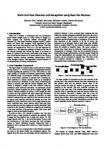
(a) ARToolkit
(b) ARTag
(c) Intersense
(d) Line Pencil
(e) Pi-Tag
Figure 1. Some examples of fiducial markers that differ both for the detection technique and for the pattern used for recognition. The black square border enables detection in (a) and (b), but while ARToolkit uses image correlation to differentiate markers, ARTag relies in error-correcting binary codes. in (c) detection happens by finding concentric ellipses and the coding is held by the appearance of the height sectors contained in them. In (d) the detection happens directly in image-space using the angular cross-ratio between lines, but the pose estimation requires a stereo camera. Finally, in (e) we show the proposed Pi-Tag that can be both detected and recognized in the image-space.
frequently used projective invariant. Almost invariably this property is exploited by detecting the border edges of a highly contrasted quadrilateral block. This happens, for instance, with the very well known ARToolkit [8] system which is freely available and adopted in countless virtual reality applications. Thanks to its ease of detection and the high accuracy provided in pose recovery [11], this solution is retained in many recent approaches, such as ARTag [4] and ARToolkitPlus [19]. These two latter methods replace the recognition technique of ARToolkit, which is based on image correlation, with a binary coded pattern (see Fig. 1). Finally, many papers suggest the use of the cross-ratio among detected points [16], [17], [10], or lines [18] as invariant properties around which to build marker systems. A clear advantage of the cross-ratio is that, being projective invariant, the recognition can be made without the need of any rectification of the image. Unfortunately, the ease of detection offered by the use of the cross-ratio often comes at the price of a high sensitivity to occlusions or misdetection as spurious or missing detection completely destroy the invariant structure. Further, cross-ratios exhibit a strongly non-uniform distribution [6], which in several situation limits overall number of distinctively recognizable patterns. In this paper we introduce a novel visual marker system that adopts the cross-ratio and other projective invariant to make possible both detection and recognition without requiring the estimation of an homography or any other technique of perspective correction. Further, our approach limits the measure instability due to the non-uniform distribution of the cross-ratio by introducing some redundancy, which can also be exploited to obtain a moderated robustness to occlusion. In addition, the detection and recognition algorithms are both very simple to implement. In the experimental section we validate the proposed approach by comparing its performance with two widely used marker systems and by testing its robustness under a wide range
of noise sources.
II.. Image-Space Fiducial Markers The proposed marker, which we named Pi-Tag (Projective invariant Tag), exhibits a very simple design. It is made up of 12 dots placed on the sides of an imaginary square. Four dots are placed on each side of this square and the corners are shared. The pattern of the dots is identical for the four sides taken two by two (note for instance that in Fig. 1 the top and left side show the same pattern, as well as the bottom and right ones). The two different patterns are not random. In fact they are created in such a way that the cross-ratio (a projective invariant property of four collinear points) of the two patterns is proportional via a fixed constant δ. The interplay between the detection of these cross-ratios in the image plane and other invariants such as straight lines and conics projections allows for a simple and effective detection and recognition approach for the Pi-Tag.
A..Projective invariants Our approach relies on four type of projective invariants. Namely, the invariance of the class of ellipses, point sets collinearity, angular ordering (on planes facing the view direction) and cross-ratio. The invariance of the class of ellipses has been extensively exploited in literature. Circular dots are easy to produce and, since they appear as ellipses under any projective transformation, they are also easy to detect by fitting on them a conic model with a low number of free parameters. In addition, while the center of the detected ellipses is not preserved under perspective, if the original dots are small enough, the positional error has been shown to be negligible for most practical purposes (in fact dots are widely adopted also for accurate tasks such as lens distortion correction, and stereo calibration).
i
j
i
j
k
h
k
h
(a) Search for a feasible starting side
(b) Second side and corner labeling
i
j
k
h
(c) Completion of the marker (if possible)
Figure 2. Steps of the marker detection: in (a) a good candidate for a starting side is found by iterating through all the point pairs (O(n2 )). In (b) for each viable solution another connected side is searched and, if found, the resulting angular ordering is used to label the found corners (O(n)). Finally in (c) the marker is completed (if possible) by finding the missing corner among all the dots left. (image best viewed in colors)
Other advantages of the elliptical fitting include the ability of using the residual error to filter out false detections and to perform gradient-based refinements. Given a set of points, projective geometry preserves neither distances nor the ratios between them. Fortunately, there are some interesting properties that still yield and can be put to use. The first one is the angular ordering of coplanar points. That is, if we take three points defining a triangle, once we have established an ordering to them (either clockwise or anti-clockwise), such ordering is maintained under any projective transformations that looks down to the same side of the plane. The second invariant related to point sets is collinearity and derives from the fact that a line is transformed again to a line under perspective. Almost all rectangular fiducial markers relies on this property in their detection stage by finding all possible lines in a scene using a wide range of different techniques. Finally, in case of four collinear points A,B,C and D, a function can be defined that is not affected by such transformations (see Fig. 3). This function is called crossratio and is defined as: cr(A, B, C, D) =
|AB|/|BD| |AC|/|CD|
(1)
where |AB| denotes the Euclidean distance between points A and B. The cross-ratio does not depend on the direction of the line ABCD but depends on the order and the relative positions between the points. The four points can be arranged in 4! = 24 different orderings which yield six different cross-ratios. Due to this fact, the cross-ratio is unlikely to be used directly to match a candidate set of points against a specific model, unless some information is available in order to assign an unique ordering to such points. Many fiducial marker systems use projective and permutation P 2 -invariants [12] to eliminate the ambiguities
M
A'
A
B'
B
C' D'
C
D
Figure 3. Cross-ratio of four collinear points is invariant to projective transformations. cr(A, B, C, D) = cr(A0 , B 0 , C 0 , D0 )
of the different orderings. For example this invariants are used to track interaction devices for augmented reality [10]. It has to be noted, however, that permutation invariance comes to the drawback of being unable to label each point in the set with respect to the reference model. This implies that is impossible to fully estimate the camera pose without relying to stereo image pairs or other features in the markers. The main idea behind the design of the proposed PiTags is to combine all the aforementioned invariants to identify each dot without ambiguities (even in presence of some occlusions) to allow fast and accurate pose estimation.
B..Marker Detection and Recognition In our design each marker is characterized by properties that does not vary among all the possible tags. Specifically, each side of the marker must be made up of exactly four dots. Moreover each pair of the four sides must share a corner dot. Finally we know by construction that the cross-ratio associated to adjacent sides must be either the same or one must proportional to the other by a known constant σ. All these properties allow to decouple the detection and recognition pipeline into two separate steps. In the detection process a set of possible marker candidates are localized in the image by exploiting the projective invariants described in the previous section. First of all, all the dots are located by searching for the ellipses present in the image (projective invariance of conics). For this purpose we use the ellipse detector supplied by the OpenCV [1] library applied to a thresholded image, but any other suitable technique would be fine. To be resilient to image gradient, a locally adaptive threshold is applied [15]. Some of the ellipses found at this stage may belong to a marker in the scene (if any), others could be possibly generated by noise or clutter. Our next task is indeed to group them into viable marker candidates, and this can be done by considering just the centroids of the ellipses (which are a very good approximation for original circle points). The first step to gather all the points belonging to a tag is to find a viable marker side. Of course this can be done by exploiting the straight line invariance. This happens by iterating over all the unordered pairs of dots and then, for each pair, checking if they are likely to be two corner points (see Fig. 2 a). This check is satisfied if exactly two other dots can be found lying closer to the straight line connecting the candidate corners than a fixed threshold. This latter parameter is expressed in pixels and, since the accuracy of the estimated ellipse center is expected to be subpixel, a threshold of one or two pixels is usually enough to avoid false negatives without the risk of including misdetected ellipses. At this point a potential side has been identified but cannot be used for pose estimation
since the points are not yet labelled and their collinearity prevents any pose estimation algorithm to work. Thus the next step needs to validate the current side candidate by finding a third corner of the marker. Again, this is done by iterating over all the dots left and, for each one, test if it forms a candidate side with one of the current corner points (i.e. by checking that the line connecting them passes through exactly two ellipses). If a pair of sides is found then it is possible to test if they belong to a marker and give a label to each corner. The test is carried on by verifying that the proportion between the cross-ratios of the sides is exactly 1 (in this case the two sides are identical) or σ (in this case we have found two sides with different patterns). The labelling happens by observing the ordering of the sides, that is conserved since always the same face of the tag is seen (see Fig. 2 b). With this step two sides are detected and labelled and the recognition could happen by comparing the obtained cross-ratio with the database of current markers. However, to be more robust, also the fourth corner can be searched with the same line-based technique. Depending on the application requirements, the search for the fourth point can be mandatory (to reduce the number of false positives and get a more accurate pose) or optional (to allow for the occlusion of at most two sides of the marker). Once the points are detected and labelled it is possible to test if they belong to an expected marker. This final step is done by computing the average between the two or four obtained cross-ratios (divided by σ if needed) and by comparing it with all the values in the database of the tags to be searched. If the distance is below a fixed threshold the marker is finally recognized. Regarding the computation complexity of the approach, it is easy to see that finding a starting side is O(n2 ) with the number of ellipses, while the two subsequent steps are both O(n). This means that if each detected point triggers the full chain the total complexity of the algorithm could be O(n4 ). However, in practice, given the relatively low probability of getting four ellipses in line, most of the starting side found lead to a correct detection. In addition, even when the starting side is not correct, it is highly probable that the cross-ratio check will stop the false matching at the second step. While a full probabilistic study would give a more formal insight, in the experimental section we will show that even with a large number of false ellipses the recognition is fast enough for real-time applications.
C..Estimation of the Camera Pose By using the detected and labelled ellipses it is now possible to estimate the camera pose. Since the geometry of the original marker is known any algorithm that solves the PnP problem can be used. In our test we used the solvePnP function available from OpenCV. However it should be
Pi-Tag Pi-Tag (refined) ARTookit ARTookitPlus
10-2
10-2
∆α [rad]
∆α [rad]
10-1
Pi-Tag Pi-Tag (refined) ARTookit ARTookitPlus
10-1
10-3
10-3
10-4
10-4 0
0.2
0.4
0.6
0.8
1
1.2
0
5
10
Angle of view [rad]
20
Pi-Tag Pi-Tag (refined) ARTookitPlus
-2
10
10-2
∆α [rad]
∆α [rad]
10-1
Pi-Tag Pi-Tag (refined) ARTookit ARTookitPlus
10-1
15
Window size [px]
10-3
10-3
10-4
10-4 20
40
60
80
100
0.1
120
0.2
0.3
0.4
0.5
0.6
0.7
0.8
Gradient Steepness
Noise [σ]
Figure 4. Evaluation of the accuracy in the camera pose estimation with respect to different scene conditions. In the first row respectively view angle and Gaussian blur are tested. In the second row we evaluate the effects of Gaussian noise (left) and illumination gradient (right, measured in gray values per image pixel). The proposed method is tested both with and without refinement. Comparisons are made with ARToolkit and ARToolkit Plus.
0.0014
ellipse refinement presented in [14]. In addition to a more accurate localization it could be useful to correct also the projective displacement of the ellipses centers. However, according to our tests, such correction gives in general no advantage and sometimes leads to slightly less accurate results. Finally we also tried the direct method outlined
Pi-Tag (refined) Pi-Tag
0.0012
∆α [rad]
0.001 0.0008 0.0006 0.0004
0.14
0.0002
1
2
3
4
5
Number of occluded ellipses
Figure 6. Evaluation of the accuracy of the estimated camera pose when some circles of the marker are occluded (note that if more than 5 dots are missing is not possible to detect the marker at all).
noted that, while the estimated ellipse centers can be good enough for the detection step, it could be reasonable to refine them in order to recover a more accurate pose. Since this is done only when a marker is found and recognized we can indulge and dedicate a little more computational resources at this stage. In this paper we used the robust
Number of false positives
0.12
0
th=0.001 th=0.005 th=0.008
0.1 0.08 0.06 0.04 0.02 0 100
110
120
130
Number of false ellipses
Figure 7. Evaluation of the number of false positive detected with respect to the number of false ellipses introduced in the scene and the threshold applied to the cross-ratio.
Figure 5. Some examples of artificial noise used for synthetic evaluation. Respectively light Gaussian noise at grazing view angle (first column), blur (second column), strong Gaussian noise (third column) and illumination gradient (fourth column). The tested markers are ARToolkit (first row), ARToolkit Plus (second row) and Pi-Tag (third row). 0.22
III.. Experimental Validation
Pi-Tag
0.2 0.18
Time [sec.]
0.16 0.14 0.12 0.1 0.08 0.06 0.04 0.02 0 0
20
40
60
80
100
120
140
Number of false ellipses
Figure 8. Evaluation of the recognition time when adding artificial false ellipses in the scene.
in [7], but we obtained very unstable results, especially with small and skewed ellipses.
In this section the accuracy and speed of the PiTag fiducial markers is evaluated and compared with the results obtained by ARToolkit and ARToolkitPlus. All the experiments have been performed on typical a desktop PC equipped with a 1.6Ghz Intel Core Duo processor. The accuracy of the recovered pose is measured as the angular difference between the ground truth camera orientation and the pose obtained. Such ground truth is known since the test images are synthetically generated under different condition of noise, illumination, viewing direction, etc. The implementations of ARToolkit and ARToolkitPlus used are the ones freely available at the respective websites. The real images are taken with a 640x480 CMOS webcam.
(a)
(b)
(c)
Figure 10. Some examples of behavior in real videos. In (a) the marker is not occluded and all the dots contribute to the pose estimation. In (b) the marker is recognized even if a partial occlusion happens. In (c) the marker cannot be detected as the occlusion is too severe and not enough ellipses are visible.
A..Accuracy and Baseline Comparisons In Fig. 4 the accuracy of our markers is evaluated. In the first test the marker is tested at increasing grazing angles and with a minimimal additive Gaussian noise. It is interesting to note that oblique angles lead to an higher accuracy (as long as the markers are still recognizable) for all the methods. This is explained by observing that the constraint of the reprojection increases with the angle of view. Still Pi-Tag shows better results both when the pose is evaluated with the original thresholded ellipses and after the refinement. In the second test we evaluated the effects of Gaussian blur, which seems to have a limited effect on all the techniques. This is mainly related to the fact that all of them performs a preliminary edge detection step, which in turn applies a convolution kernel. Thus is somewhat expected that an additional blur does not affect severely the marker localization. In the third test an additive Gaussian noise was added to images with an average view angle of 0.3 radians and no artificial blur added. The performance of all methods get worse with increasing levels of noise
Recognition Rate
1
0.8
0.6
0.4
0.2
and ARToolkitPlus, while in general more accurate than ARToolkit, breaks when dealing with a noise with a std. dev. greater than 80 (pixel intensities goes from 0 to 255). Finally, the effect of illumination gradient is tested only against ARToolkit Plus (since ARToolkit cannot handle this kind of noise), which again obtains lower accuracy and breaks early. Overall these experiments confirm that Pi-Tag always outperforms the other two tested techniques. In practical terms the improvement is not negligible, in fact an error as low as 10−3 radians still produces a jitter of 1 millimeter when projected over a distance of 1 meter. While this is a reasonable performance for augmented reality applications, it can be unacceptable for obtaining precise contactless measures.
B..Resilience to Occlusion and False Ellipses One of the characteristics of Pi-Tag is that it can deal with moderate occlusion. In Fig. 6 we show how occlusion affects the accuracy of the pose estimation (i.e. how well the pose is estimated with fewer dots regardless to the ability of recognize the marker). Albeit a linear decreasing of the accuracy with respect to the occlusion can be observed, the precision is still quite reasonable even when almost half of the of the dots are not visible (comparing it with the results shown in Fig. 4). This is especially true for the refined version of the tag. In Fig. 7 we evaluate the proportion of false positives obtained by introducing a large amount of false ellipses. When the threshold on the cross-ratio is kept tight it is possible to obtain a very low rate of false positives even with a large number of random dots.
C..Performance Evaluation 0 0.001
0.002
0.003
0.004
0.005
0.006
Threshold
Figure 9. Evaluation of the recognition rate (on a real video of about ten minutes) with respect to the threshold applied to the cross-ratio.
Our tag system is designed for improved accuracy and robustness to occlusion rather than for high detection speed. This is quite apparent in Fig. 8, where we can see that the recognition could require from a minimum
of about 10 ms (without false ellipses) to a maximum of about 150 ms. By comparison ARToolkit Plus is about an order of magnitude faster [19]. However, it should be noted that, despite being slower, the frame rates reachable by PiTag (from 100 to about 8/10 fps) can still be deemed as usable even for real-time applications (in particular when few markers are viewed at the same time).
D..Behavior with Real Videos In addition to the evaluation with synthetic images we also performed some qualitative and quantitative tests on real videos. In Fig. 10 some experiments with common occlusion scenarios are presented. Note that when at least two sides are fully visible the marker is still recognized and the correct pose is recovered. In Fig. 9 we show the proportion of recognized markers in a ten minute videos subject to several different viewing conditions with respect to the cross-ratio threshold. It is interesting to note that even with small threshold a full recall can be obtained (in comparison with threshold of Fig. 7). At last, in Fig. 11 an inherent shortcoming of our design is highlighted. The relatively small size of the base features may result in a failure of the ellipse detector whereas the tag is far away from the camera or very angled, causing the dots to become too small or blended.
IV. . Conclusions The novel fiducial marker proposed in this paper exploits the interplay between different projective invariants to offer a simple, fast and accurate pose detection without requiring image rectification. Our experimental validations shows that the precision of the pose recovered outperforms the current state-of-the-art. In fact, even if relying only on a maximum on 12 dots, the accuracy achieved by using elliptical features has been proven to give very satisfactory results even in presence of heavy artificial noise, blur and extreme illumination conditions. This accuracy can be further increased by using an ellipse refinement process that takes in account image gradients. Marker design is resilient to moderate occlusion without severely affecting
Figure 11. Recognition fails when the marker is angled and far away from the camera and the ellipses detectors cannot detect the circular features.
its detection or pose estimation accuracy. The internal redundancy exhibited by its design allows to compensate the strongly non-uniform distribution of cross-ratio and also permits a good trade-off between the recognition rate and false-positives. Even taking in account the limited number of discriminable cross-ratios, the overall number of tags that can be generated is reasonable. The design proposed leaves plenty of space in the marker interior for any additional payload. Since it works entirely in imagespace, our proposed method is affected by image resolution only during the ellipse detection step and is fast enough for most real-time augmented reality applications. Of course those enhancements do not come without some drawbacks. Specifically, the small size of the circular points used can lead the ellipse detector to miss them at low resolution or if the viewing point is very angled with respect to the marker’s plane. This limitations can be partially avoided by increasing the ratio between the size of the ellipses and the size of the marker itself, thus limiting the range of possible cross-ratio values and the total number of different tags that can be successfully recognized.
References [1] G. Bradski and A. Kaehler. Learning OpenCV: Computer Vision with the OpenCV Library. O’Reilly Media, Inc., 1st edition, 2008. [2] Y. Cho, J. Lee, and U. Neumann. A multi-ring color fiducial system and a rule-based detection method for scalable fiducial-tracking augmented reality. In Proceedings of International Workshop on Augmented Reality, 1998. [3] D. Claus and A. W. Fitzgibbon. Reliable automatic calibration of a marker-based position tracking system. In IEEE Workshop on Applications of Computer Vision, 2005. [4] M. Fiala. Designing highly reliable fiducial markers. IEEE Trans. Pattern Anal. Mach. Intel., 32(7), 2010. [5] L. Gatrell, W. Hoff, and C. Sklair. Robust image features: Concentric contrasting circles and their image extraction. In Proc. of Cooperative Intelligent Robotics in Space, Washington, USA, 1991. SPIE. [6] D. Q. Huynh. The cross ratio: A revisit to its probability density function. In Proceedings of the British Machine Vision Conference BMVC 2000, 2000. [7] J. Kannala, M. Salo, and J. Heikkil¨a. Algorithms for computing a planar homography from conics in correspondence. In British Machine Vision Conference, 2006. [8] H. Kato and M. Billinghurst. Marker tracking and hmd calibration for a video-based augmented reality conferencing system. In Proceedings of the 2nd IEEE and ACM International Workshop on Augmented Reality, Washington, DC, USA, 1999. IEEE Computer Society. [9] V. A. Knyaz, H. O. Group, and R. V. Sibiryakov. The development of new coded targets for automated point identification and non-contact surface measurements. In 3D Surface Measurements, International Archives of Photogrammetry and Remote Sensing, 1998. [10] R. V. Liere and J. D. Mulder. Optical tracking using projective invariant marker pattern properties. In Proceedings of the IEEE Virtual Reality Conference. IEEE Press, 2003.
[11] M. Maidi, J.-Y. Didier, F. Ababsa, and M. Mallem. A performance study for camera pose estimation using visual marker based tracking. Mach. Vision Appl., 21, 2010. [12] P. Meer, R. Lenz, and S. Ramakrishna. Efficient invariant representations. Int. J. Comput. Vision, 26:137–152, 1998. [13] L. Naimark and E. Foxlin. Circular data matrix fiducial system and robust image processing for a wearable visioninertial self-tracker. In Proceedings of the 1st International Symposium on Mixed and Augmented Reality, ISMAR ’02, Washington, DC, USA, 2002. IEEE Computer Society. [14] J. Ouellet and P. Hebert. Precise ellipse estimation without contour point extraction. Mach. Vision Appl., 21, 2009. [15] J. Sauvola and M. Pietikainen. Adaptive document image binarization. Pattern Recognition, 33(2):225 – 236, 2000. [16] L. Teixeira, M. Loaiza, A. Raposo, and M. Gattass. Augmented reality using projective invariant patterns. In Advances in Visual Computing, volume 5358 of Lecture Notes in Computer Science. Springer Berlin / Heidelberg, 2008. [17] V. S. Tsonisp, K. V. Ch, and P. E. Trahaniaslj. Landmarkbased navigation using projective invariants. In Proceedings of the 1998 IEEE Intl. Conf. on Intelligent Robots and Systems, Victoria, Canada, 1998. IEEE Computer Society. [18] A. van Rhijn and J. D. Mulder. Optical tracking using line pencil fiducials. In Proceedings of the eurographics symposium on virtual environments, 2004. [19] D. Wagner, G. Reitmayr, A. Mulloni, T. Drummond, and D. Schmalstieg. Real time detection and tracking for augmented reality on mobile phones. IEEE Transactions on Visualization and Computer Graphics, 99, 2010.