Journal of VLSI Signal Processing 28, 115–128, 2001 c 2001 Kluwer Academic Publishers. Manufactured in The Netherlands. °
Implementation of a Communications Channelizer using FPGAs and RNS Arithmetic∗ ¨ UWE MEYER-BASE Department of Electrical and Computer Engineering, FAMU-FSU College of Engineering, Tallahasser, FL 32310-6046 ANTONIO GARC´IA Dpto. Ingenier´ıa Inform´atica, Universidad Aut´onoma de Madrid FRED TAYLOR High Speed Digital Architecture Laboratory, University of Florida, Gainesville, FL 32611-6130 Received July 1999; Revised December 1999
Abstract. Field-programmable logic (FPL), often grouped under the popular name field-programmable gate arrays (FPGA), are on the verge of revolutionizing sectors of digital signal processing (DSP) industry as programmable DSP microprocessor did nearly two decades ago. Historically, FPGAs were considered to be only a rapid prototyping and low-volume production technology. FPGAs are now attempting to move into the mainstream DSP as their density and performance envelope steadily improve. While evidence now supports the claim that FPGAs can accelerate selected low-end DSP applications (e.g., FIR filter), the technology remains limited in its ability to realize high-end DSP solutions. This is due primarily to systemic weaknesses in FPGA-facilitated arithmetic processing. It will be shown that in such cases, the residue number system (RNS) can become an enabling technology for realizing embedded high-end FPGA-centric DSP solutions. This thesis is developed in the context of a demonstrated RNS/FPGA synergy and the application of the new technology to communication signal processing. Keywords: field-programmable logic (FPL), field programmable gate array (FPGA), complex programmable logic devices (CPLD), digital signal processing (DSP), residue number system (RNS), channelizer, zero-IF filter 1.
Introduction
Experts generally agree that future signal processing systems will contain deeply embedded DSP elements having a performance envelop at least 10× greater than that possessed by the existing DSP µp art. These designs will normally manifest themselves as an application specific integrated circuit (ASIC). Market forces require that ASIC solutions be rapidly developed in order to insure early market entry. This market reality ∗ Portions
of the results presented here have been in presented at the IEEE ICASSP 97/98 and SPIE 99 conferences.
makes FPGAs a potentially attractive facilitating technology in cases where the high non-reoccurring engineering costs (NRE) of cell-based (standard cell), or custom VLSI solutions cannot be justified. This claim, of course, is predicated on the FPGA solution meeting all other stated performance requirements. It will be shown in the next section that FPGA are actually multiply-accumulate (MAC) deficient. Since MACs are a fundamental to virtually every DSP operation, it will be argued that the path to successful FPGA assimilation into the greater DSP arena is predicated on improving FPGA-enabled MAC performance. One such candidate is the residue number system or RNS [1].
116
Meyer-B¨ase, Garc´ıa and Taylor
Table 1. Adder and multiplier speed and complexity versus wordwidth. ADD Bits MSPS # LE
MUL
8
16
26
32
9×9
137
73
51
45
71
12 × 12 69
8
16
26
32
217
328
The RNS MAC has been shown, in numerous academic and industrial studies, to define a compact, highbandwidth, high-precision DSP solution in a variety of DSP instances. The RNS is just now beginning to appear as a commercial off-the-shelf (COTS) cell-based technology for use in high-end DSP applications. The potential impact of the RNS on FPGA-centric system design is, at this time, unquantified. FPGAs are being aggressively touted as a viable DSP ASIC technology by FPGA vendors. Vendors and IP providers point to FPGA-enabled designs whose performance far surpasses those of systems designed using DSP µps in implementing some baseline DSP operations, such as finite impulse response (FIR) digital filters. Regardless of the marketing hyperbole, it should be appreciated that FPGAs possess an intrinsically weak general-purpose arithmetic unit that limit their DSP applicability, especially in high-end applications. To illustrate, consider the design of 2’s complement ripple carry adder with fast carry chains. The design of DSP arithmetic primitives, reported in Table 1, are based on a Flex10K device where each logic element (LE) is a 23 × 1 table. It can be seen that the adder speed reduction is highly correlated to precision. While 8-bits may be marginally acceptable for some 100+ MIPS applications, most DSP solutions require significantly higher precision. Achieving both high-precision and high-bandwidths with an FPGA is therefore problematic. Reported FPGA-enabled DSP solutions have, in fact, not been based upon faster arithmetic units, but rather on finding ways of masking arithmetic deficiencies. Table 2.
It will be developed in the next section that the two most commonly encountered masking methods are distributed arithmetic (DA) [2] and reduced adder graphs (RAG) [3]. It will be discovered that these techniques apply to the implementation of low-order low-precision fixed-point DSP algorithms having fixed coefficients (e.g., FIRs, IIRs, and DFT). This defines a very narrow window of DSP/FPGA synergy. Implementing run-time, fully programmable high-bandwidth, high-precision, real and complex arithmetic DSP objects with FPGAs remains today, a challenging problem. Unless this arithmetic barrier can be overcome, FPGAs will continue to be primarily prototyping technology and never become a viable DSP facilitating, let alone, enabling technology. What is needed is a means of overcoming the arithmetic limitations of FPGAs. The paper presents a promising approach to this challenge based on recent development of cell-based RNS arithmetic units. It will be shown that in the RNS arithmetic operations are implemented as a set of concurrent primitive operations within non-communicating small wordlength channels. As a result, the RNS is highly synergistic with existing FPGA architectures that naturally partition a device into small wordlength independent channels. To illustrate this thesis, the implementation of an advanced communication receiver (channelizer) will be presented. The design will demonstrate that the RNS can enable high-end solutions that existing FPGA design methodology cannot achieve. 2.
FPGA Overview
Field programmable logic (FPL) devices are marketed in a variety of names, including field programmable gate arrays (FPGA) and complex programmable logic devices (CPLD). The two technology suppliers, Xilinx and Altera, are reported in Table 2. FPGAs are considered fine grain devices, consisting of small logic cells (LC) (e.g., Xilinx XC4000) and various routing
Comparison of common FPGA resources.
FPGA
Logic unit
Routing hierarchy
Memory
Largest part
Xilinx 4000
Configurable logic blocks (CLB), two 4-bit LUT, one 3-bit LUT, F/F
5-level routing (adjacent, double, quad, long, and global)
32-bits per CLB
40125XV; 64 × 64 CLB array, 448 user I/O
Altera Flex 10K
Logic element (LE), logic block of 8 LEs, 4-bit LUT, F/F
3-level (local, fast, global)
Embedded array (EAB) of 2K bits, 3-12 EABs per chip
EPF10K250, 1520 LABs, 470 user I/O
Channelizer using FPGAs and RNS
canals (short, local, and long-lines). CPLDs have comparatively larger logic blocks with fast busses connecting array blocks (e.g., Altera FLEX [4]). The historical advantage of FPLs has been their “in circuit programmability” and ability to support “rapid prototyping.” FPLs have been promoted in custom computing machine (CCMs) applications where they have been reported to achieve speed-up-factors ranging from 10–1000 compared to conventional workstations [5, Table 1]. FPLs can support accelerated arithmetic using fast carry chains (Xilinx XC4000, Altera FLEX) that can be used to implement high-bandwidth MACs. This motivates the claim by FPGA devotees that the technology is not just for prototyping anymore, but rather is a viable DSP facilitating technology. They note that complexity levels have reached 1M gates, and to the fact that the technology, if properly interpreted and configured, can: – exploit algorithm parallelism: implement multiple MAC calls – maximize gate efficiency: remove zero productterms – exploit pipelining: each logic cell contains a register and therefore requires no additional pipelining resources FPGA advocates point to a demonstrated 50× speed up in pixel averaging, 30× in pattern recognition, and 100× in edge detection over a TMS320C30 solution [6]. While comparing a fixed-point ASIC to a floating point DSP µp is not a true comparison, such examples do demonstrate that when properly employed, FPGAs can be a competitive DSP technology. The FPGA DSP claim of superiority to date are actually attributable to the application selection rather than intrinsic technological advantages. Using DA or RAG techniques, engineers have been able to accelerate selected linear time-invariant (LTI) digital filters and transforms (i.e., constant coefficient). A simple audit of the DSP vendor and IP support libraries of Xilinx and Altera illustrates this point. What is important to note is DA and RAG FPGA-enabled DSP objects are intrinsically of low-precision and low-order. Absent from this list are programmable high-end objects such as run-time programmable precise filters, adaptive filters, neural nets, and so forth. 3.
Residue Number System (RNS)
The silicon area (complexity) associated with a constant-speed fixed-point MAC unit is generally
117
considered to geometrically increase with word-length. The antithesis is the RNS which establishes a linear relationship between MAC speed and silicon area [1]. The RNS, therefore, provides an opportunity to overcome the precision barrier in high-performance FPL applications. RNS integer arithmetic is performed concurrently within parallel non-communicating small word length channels. An RNS system is defined in terms of a basis set {m 1 , m 2 , . . . , m L } of relatively prime positive integers called moduli. The dynamic range of the resulting system is defined Q L by the product m i . RNS arithof the moduli and is given by M = i=1 metic is defined with respect to the ring isomorphism: ZM ∼ = Zm 1 × Zm 2 × · · · × Zm L
(1)
Specifically, Z M = Z/M corresponds to the ring of integers modulo M. The mapping of an integer X into the RNS is defined to be the L-tuple X = (x1 , x2 , . . . , x L ) where xi = X mod m i , for i − 1, 2, . . . , L. This is generally assumed to be a straightforward process that can be directly implemented in hardware using small lookup tables. Defining ¤ to be either the algebraic operations +, − or ·, it follows that if 0 ≤ Z < M, then: Z=X
¤
Y
mod M
(2)
is isomorphic to Z = (z 1 , z 2 , . . . , z L ) where: z i = (xi
¤
yi ) mod m i i = 1, 2, . . . , L
(3)
It should be self-evident that the RNS arithmetic is performed in parallel within small non-communicating (i.e., carry-free) wordlength channels whose word width is bounded by n i = dlog2 (m i )e, where n i ≤ 8-bits (typically). In practice, most RNS arithmetic systems use small RAM or ROM tables to implement the modular mappings z i = (xi ¤ yi ) mod m i as LUT calls. Using direct LUT operations can, however, create a technological problem. If the address of the LUT is formed by concatenating the arguments (xi ¤ yi ) then a 2(2ni ) × n i -bit table would be required. A 7-bit moduli, for example, would require a 114K bit table which is beyond the current capabilities of a modern FGPA. Specifically, consider again an n i -bit moduli and two residues, say xi and yi used to create a product z i = (xi · yi ) mod m i , which is n i -bits wide. If the desired moduli size is on the order of 6 to 8-bits an unreasonable 12 to 16-bit TLU address space results. The
118
Meyer-B¨ase, Garc´ıa and Taylor
address space requirement can, however, be reduced by nearly half by using the “quarter square” algorithm: z i = (xi · yi ) mod m i ¶ µ (xi − yi )2 (xi + yi )2 − mod m i = 4 4 = (8(xi , yi ) − 2(xi , yi )) mod m i
(4) (5) (6)
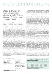
where 8(xi , yi ) and 2(xi , yi ) are obtained from LUT calls using the sum and difference of residues as an (n i + 1)-bit wide address. Compared to a direct implementation of a standard RNS multiplier, the table requirement are reduced from 22ni ×n i -bits to 2×2ni +1 × n i = 2ni +2 × n i -bits. The savings for a 7-bit moduli is a factor of 32. What is more important is that the multiplication LUTs can now be contained within an 8-bit FPGA channel. As a result, 7-bit moduli could be used in conjunction with 8-bit FPGA tables to implement a standard RNS multiplier. Conversion from the RNS to integers is performed using either the Chinese Remainder Theorem (CRT) or mixed-radix conversion (MRC) algorithm. The direct implementation of either form can be awkward but efficient forms of these algorithms can be found in the literature. Demonstration RNS systems have been built as custom VLSI [7] (see Fig. 1), GaAs, and LSI systems [1]. These studies have demonstrated the speed-area advantage of the RNS in implementing MAC-intensive
algorithms. The 0.8µ system shown in Fig. 1 contains twenty-four 32-bit MACs. Running at the speed of a TMS320C5x MAC, the RNS MAC’s footprint is 1/14th the C5x’s. For a small wordlengths RNS can provide a significant speed-ups [8] using the 24 × 2 bit tables found in a Xilinx XC4000 FPGAs. For larger moduli, the 28 × 8 bit tables belonging to the Altera FLEX CPLDs are beneficial in designing RNS arithmetic and RNS-to-integer converters. With the ability to support larger moduli, the design of high-precision FPL systems becomes a practical reality. There are several variations of the RNS theme which apply to DSP. One of the popular variants is based on the use of “index” arithmetic [9]. It is similar, in some respects, to the form taken by the logarithmic number system (LNS). Computation in the index domain is based on the fact that that if all the moduli are chosen to be primes pi , then it is known from number theory that there exists a primitive element (i.e., generator γ ) such that: β ≡ γ α mod p
(7)
The element γ generates all elements in the field Z p , excluding zero (denoted Z p /{0}). There is, in fact, a one-to-one correspondence between the integers β in Z p /{0} and the exponents α which are defined in Z p−1 . As a point of terminology, the index with respect to the generator γ and integer β, is denoted α = indγ (β). For notational purposes the element β = 0 is denoted g −∞ = 0. The structure of this system suggests that arithmetic requires that the exponent α be manipulated. This is referred to as index algebra. Multiplication of RNS numbers can be preformed in the index-domain using the following procedure: 1. transform X and Y in the index domain (i.e., X = γ α and Y = γ β 2. add the index values modulo p − 1 (i.e, ν = (α + β) mod ( p − 1) 3. transform the sum back to the original domain (i.e., P = γ ν)
Figure 1.
RNS systolic array chip [7].
If the data being processed is in index form, then multiplication can performed using only exponent addition mod( p − 1). The advantage gained by index processing is found in the fact that the multiplicative table size, when compared to the standard RNS of comparable moduli size, is reduced from 22n ×n to 2n ×n based on n-bit moduli. If the modulo adder in step two is replace by a binary adder, then the multiplier correction
Channelizer using FPGAs and RNS
table is 2(n+1) × n, or twice as large as that requiring modulo adders. In either case, this can be beneficial in FPGA designs where only small tables are generally available. The advantage gained in index multiplication, however, is somewhat mitigated when index addition is encountered. Addition can technically be performed by converting index-coded RNS data back into the RNS domain where the summands can be added. Once the sum is formed, the result can be mapped back into the index-domain. Another approach is based on Zech-logarithms [10], where a Zech-logarithm is defined as: Z (k) = indγ (1 + γ k ) ←→ γ Z (k) = 1 + γ k
(8)
The sum of index-coded numbers, say X and Y , is expressed as: z = x + y = γ αz = γ α x + γ α y ¡ ¢ ¡ ¢ = γ αx 1 + γ α y −αx = γ α y 1 + γ αx −α y
119
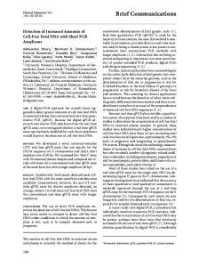
the two-tuple Z = X ± jY and complex addition requires two real adds, and complex multiplication is defined by four real products, an addition and subtraction (albeit short wordlength). This condition is radically altered in the quadratic RNS, or QRNS. The QRNS is based on known properties of Gaussian primes of the form p = 4k + 1, where k is a positive integer. The importance of this choice of moduli is found in the factorization of the polynomial x 2 +1 given by Gauss. For Gaussian primes, the roots of x 2 = −1 are no longer imaginary by rather two real roots, denoted ˆ and −ˆ,. Specifically ˆ and −ˆ are real integers belonging to the residue class Z p . Converting a RNS complex number a + jb into the QRNS is accomplished by applying the transform f : Z2p → Z2p as follows: f (a + jb) = (a + ˆb mod p, a − ˆb mod p) = (A, B)
(11)
In the QRNS, addition and multiplication is component-wise, and is defined to be: (9)
(a + jb) + (c + jd) ↔ (A + C, B + D) mod p.
or, in terms of a Zech-loragrithm:
(12)
γ αz = γ α y + γ Z (αx −γ y ) ←→ αz = α y + Z (αx − α y ). (10) Adding numbers in the index domain requires one addition, one subtraction, and a Zech-LUT. The special case a + b ≡ 0 corresponds to the case where [11]:
(a + jb)(c + jd) ↔ (AC, BD)
(13)
In the QRNS domain, complex multiplication requires only two real multiplications, while two’s complement multiplication requires four real multiplier, a real add, and real subtraction to complete. Finally the conversion of a QRNS digit, back into the RNS, is defined by: ¡ ¢ f −1 (A, B) = 2−1 (A + B) + j (2ˆ)−1 (A − B)
−x ≡ y mod p ←→ γ αx +( p−1)/2 ≡ γ β mod p. That is, the sum is zero if, in the index domain, β = α + ( p − 1)/2 mod ( p − 1). Therefore implementing a basic DSP object, with Zech logarithm, will reduce the number of necessary LUTs for FPLs to the minimum of one per MAC cell. Another RNS variant applies to case where complex arithmetic is required (e.g., DFT) and, communications applications. Traditional logic states that the roots to the quadratic equation x 2 = −1 are defined over the complex field. That is, in the complex RNS (CRNS) the roots of x 2 = −1 are complex and √ defined in terms of the imaginary operator = ± −1. As a consequence, complex RNS numbers are defined by
mod p
mod p, (14) Figure 2 graphical interprets the mappings between the CRNS and QRNS.
Figure 2.
CRNS ↔ QRNS conversion.
120
4.
Meyer-B¨ase, Garc´ıa and Taylor
FPL RNS Implementation
Table 3.
Modulo adder complexity: FLEX10K 3ns device. Bits
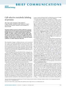
In order to facilitate efficient RNS-centric FPGA designs, a collection of RNS macros were developed for a target Altera technology. For an Altera CPLD design, the VHDL description was used because it provided a flexibility design environment that could be precisely controlled and optimized. For the VHDL approach, structural (i.e. component instantiation) and behavioral descriptions yielded similar results. The structural designs, however, produced synthesized results that were easier to post-optimized. For both standard and index RNS arithmetic, the core element is a modular adder. Several modular adder designs are shown Fig. 3 [12]. Using only LCs, the design of Fig. 3(a) is realized. The Altera FLEX CPLD contains a number of 2K bit ROMs and/or RAMs (EABs) which can be configured as 28 × 8, 29 × 4, 210 × 2, or 211 × 1 tables and used for modulo m i correction, as shown in Fig. 3(b). Table 3 summarizes the re-designed 6−, 7−, and 8-bit modulo adder [13]. Although the ROMs shown in Fig. 3 support highspeed LUTs, the ROM itself produces a four cycle pipeline delay. Furthermore, the number of on-chip ROMs are limited. ROMs, however, are required for
Pipeline stages
7
8
MPX
0
41.3 MSPS 27 LC
46.5 MSPS 31 LC
33.7 MSPS 35 LC
MPX
2
76.3 MSPS 16 LC
62.5 MSPS 18 LC
60.9 MSPS 20 LC
MPX
3
151.5 MSPS 27 LC
138.9 MSPS 31 LC
123.5 MSPS 35 LC
86.2 MSPS 7 LC 1 EAB
86.2 MSPS 8 LC 1 EAB
86.2 MSPS 9 LC 2 EAB
ROM 2
the scaling schemes. Compared to the pipelined design shown in Fig. 3 (b), the multiplexed-adder (MPX-Add) shown in Fig. 3 (a) runs at a reduced speed even if a carry chain is added to each column. The pipelined design requires the same number of LCs as the unpipelined version, but is expected to runs about twice as fast. Maximum throughput occurs when the adders are implemented in two blocks (where each block has eight LCs for Altera FLEX 10K devices) within 6-bit pipelined channels. Several other RNS basic building blocks are required to support RNS designs. The list includes modulo adder for the index domain (i.e. modulo multiplier), Zech MAC cells, code converters (BIN→RNS and an RNS→BIN) based on an ²−CRT algorithm. Altera VHDL software does not allow generic clauses. Therefore gawk and C programs have been developed for an automatic generation of the basic building blocks by specifying the desired blocks. With these library elements, standard and index RNS arithmetic systems can be designed. 5.
Figure 3. Modular addition with CPLD. (a) MPX-Add and MPXAdd-Pipe. (b) ROM-Pipe.
6
FPGA Channelizer Implementation
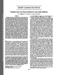
A typical modern communication receiver is shown in Fig. 4. The received analog signal is mixed with locally generated signal, and bandpass filtered. In the process the received wideband signal is split into quadrature channels (I and Q) that is digitized. The digital section of the receiver is called a channelizer or zero-IF demodulator The channelizer maps RF (or near RF) directly to baseband. The commercial imperative is to reduce the complexity of digital portion of the receiver to ideally a single chip. For mobile applications, a premium is also placed on power dissipation (active and standby).
Channelizer using FPGAs and RNS
Figure 4.
IF incoherent receiver with sin/cos mixer.
Figure 5.
Harris HSP43320 Hogenauer decimating filter.
The interface between the analog and channelizers is therefore based on maximum data conversion rate and power/complexity decision. Converting signal from, or near RF-rates to baseband is a non-trivial problem. For many typical wireless communications problems, signal decimation rates on the order of 103 or higher needs to be achieved. The preferred design methodology is called a Hogenauer architecture [4]. An example of a Hogenauer-enabled channelizer is shown in Fig. 5 as the lowpass filters (LFP). The advantage of the Hogenauer architecture is: – the preprocessor (called a Hogenauer filter) is a MAC-free multirate lowpass filter and, being MACfree is capable running at a high real-time rate – the postprocessor is a basic FIR “housekeeping” filter running at a low data rate. The theoretical foundations of a Hogenauer channelizer are well understood but represent a significant
121
FPGA design challenge. Arithmetic in a Hogenauer filter section must be exact and can often exceed 50bits wordwidths. Large arithmetic wordwidths immediately create a barrier to FPGA implementation. The RNS, however, provides a mechanism of achieving exact high-precision MAC operations within independent small wordlength channels. To appreciate the need for the RNS in this case, the mechanics of a Hogenauer channelizer will be briefly reviewed. 6.
Hogenauer Filter
A Hogenauer filter, or as it is sometimes called, a cascade integrator comb (CIC) filter, has been proven to be capable of performing high decimation-rate channelization at high input data rates. Figure 6(a) illustrates a three stage CIC filter consisting of a three stage integrator, a sampling rate reduction by R (decimation), and a three stage three comb filter. Notice that the only logic elements in the design are registers and adders (i.e., MAC-free).
122
Meyer-B¨ase, Garc´ıa and Taylor
(a)
Figure 7.
CIC transfer function ( f s is sampling frequency at input).
(b) Figure 6. CIC filter. (a) Each stage 26 Bit. (b) Detail design with base removal scaling (BRS).
The transfer function of a S stage CIC system is given by: µ H (z) =
1 − z −RD 1 − z −1
¶S (15)
The S poles of the CIC filter are located at z = 1 (i.e., DC) and the zeros are distributed along the periphery of the unit circle, appearing with multiplicity S on π/(R D) centers. The S zeros at z = 1 are annihilated by the S poles residing at the same location. The result is that the transfer-function behaves as a classic S stage “moving average” filter. The CIC filter maximum gain occurs at DC (i.e., z = 1) and has a value of Bgrow = (RD) S , or b = log2 Bgrow in bits. This value can be substantial as evidenced by the need for a 56-bit dynamic range in Harris HSP43220 [15] channelizer shown in Fig. 5. Furthermore, it is fundamentally important the CIC arithmetic be performed Exactly since the integrator section, during run-time, will constantly be incurring modulo (N ) overflows (N is the CIC dynamic range). The comb filter section must compensate for the integrator’s modulo (N ) overflows by unwrapping the result modulo (N ) an equal number of times. Any rounding or approximation in this process would be fatal. The Harris HSP43220, for example, uses an exact 2’s-complement 56-bit code to satisfy this requirement. To illustrate, assume that the input wordwidth to the 3 stage RNS CIC filter, shown in Fig. 6(a), is 8-bits. For D = 2, R = 32, or DR = 2 · 32 = 64, an
internal wordwidth of W = 8 + 3 log2 (64) = 26 bits is needed to insure that no run-time overflow will occur. The output wordwidth would normally be a value significantly less then W , say 10-bits. Hogenauer [14] noted it is possible to design each stage of the CIC section to have “just enough” dynamic range to insure an arithmetically correct outcome. Figure 7 shows a “pruning” architecture as suggested by Hogenauer. If the ratio of signal bandwidth to sampling frequency is, for instance 1/32, then the aliasing suppression is 89.6 dB and the maximum passband attenuation is 0.17 [14, Tables 1 and 2]. These facts, along with a highbandwidth requirement, motivate the use of RNS to implement CIC filters with FPGAs. A pipelined FPGA integrator section needs the same number of LCs as an un-pipelined version, and would run about twice as fast. Maximum throughput occurs when the adders are implemented in two blocks (where each block contains 8 LCs for Altera FLEX 10K devices), within six-bit pipelined channels. One additional pipeline delay, for the modulo adder, corresponds to a non-recursive transfer function A(z) = z −2 which introduces no significant processing problem. The accumulator, however, is recursive and an additional delay is introduces a second pole at one half the sampling frequency (i.e., π [16, Fig. 1]). Because the transfer function of the pipelined accumulator satisfies F(z) = z −2 /(1 − z −2 ), the pole at π can be compensated for by a (modulo m i ) comb filter with a delay of one (i.e., G(z) = (1 − z −1 )z −2 ). The integrator section, with pole compensation, then becomes F(z) · G(z) = z −4 /(1 − z −1 ) as desired. In a high decimation CIC application, it can be assumed that an anti-aliasing filter provides sufficient suppression of
Channelizer using FPGAs and RNS
Figure 8.
123
BRS and ε-CRT conversion steps.
signal components near π. A second passband located at π is introduced by the recursive pipelined accumulator but introduces no additional aliasing. The six-bit wide pipelined accumulators can then developed without pole compensation. As a design example, consider a three stage CIC filter having 8-bit input, 10-bit output, D = 2, and R = 32. The required maximal dynamic range is 26bits. For the RNS implementation, a 4 modulus system is chosen consisting of the relatively prime moduli (256, 63, 61, 59) (i.e., one 8-bit two’s complement (TC) and three 6-bit moduli). The output scaling of the RNS system is implemented using the ε-CRT at a cost of 8 tables and 3 TC adders [17, Fig. 1], or (as shown in Fig. 8) with a base removal scaling (BRS) algorithm based on two 6-bit moduli (which occur in the same fashion in the mixed radix conversion scheme [18]) and a ε-CRT for the remaining 2 moduli. This approach uses a total of 5 modulo adder and 9 ROM tables, or 7 tables if the multiplicative inverse ROM and the εCRT are combined. The following table shows speed in MSPS and used LCs and EABs for the three scaling schemes.
Type
ε-CRT
BRS-ε-CRT (Speed data for BRS m 4 only)
MSPS
58.8
70.4
58.8
#LC
34
87
87
8
9
7
#Table (EAB)
BRS-ε-CRT combined ROM
The decrease in speed to 58.8 MSPS for scaling schemes #1 and #3 are caused by the fact that a 10bit ε-CRT table address must be placed in different
FPGA rows (each row has only one EAB). This, however, introduces no system speed decrease because the scaling is applied at the lower (output) sampling rate. For the BRS-ε-CRT, it is assumed that only the BRS m 4 part (see Fig. 8) must run at the input sampling rate, while BRS m 3 and ε-CRT runs at the output sampling rate. Some additional resources can be saved based on the architecture presented in Fig. 6(b). Here the BRSε-CRT is used to reduce the bit-width found in earlier filter sections. The early use of ROMs decreases the possible throughput from 76.3 to 70.4 MSPS which is the maximum speed of the BRS with m 4 . At the output, the efficient ε-CRT scheme was employed. The following table concludes the three implemented filter realization without including the scaling data.
Type MSPS #LC
6.1.
TC 26 Bit 49.3 343
RNS 8, 6, 6, 6 bit
Detailed bit-width RNS design
76.3 559
70.4 355
Modulation and Postprocessing
Referring to Fig. 4, it can be seen that digital modulators exist to the left of the channelizer. A high-speed ADC unit, operating at or near RF frequencies, resides at the analog-digital-domain boundary. For sampling rates ≥ 100 MHz, precision is practically limited to 12-bits or less. The output of the ADC can be either binary, or directly mapped into standard or index RNS L-tuples. The product modulators can be implemented using a standard or indexed RNS multiplier. The difference would be that the standard RNS multiplier would
124
Meyer-B¨ase, Garc´ıa and Taylor
require a multiplicative LUT and the index multiplier is simply a modulo pi adder. All these options can be implemented with an FPGA to varying degrees of acceptability. A fast 2’s complement 12 × 12-bit multiplier can be built using 9 EABs or 328 LCs, and would run at 69 MHz. A comparable index RNS multiplier, based on three 7-bit moduli, would come in at 2 EABs or 260 LCs per moduli for a total of 6 EABs or 780 LCs, and would run at 86 MHz rate. This points to an important observation supported by numerous design studies which states that for low resolution cases, the RNS benefit is marginal. A RNS advantage is, rapidly gained for high-end high-precision applications (e.g., CIC filter). In the case under study, due to the assumed short wordlength of the digitized data, it may be preferred to use a traditional 2’s complement digital mixer and then map the output into the standard RNS for CIC processing. If index RNS is used, data would need to be converted to standard RNS before being CIC processed in the manner developed in the previous section. A standard RNS mixer design is also possible using the quarter-square algorithm. The channelizer output is a baseband (low sample rate) signal sampled at a highly decimated rate. The channelizer output can be taken directly from the CIC section or from a post-processing FIR. The magnitude frequency response of the CIC section is that of a Sstage moving average filter (i.e., sin(x)/x). A low data rate FIR can be used to shape the CIC baseband which resides between DC and the first null of the Hogenauer filter (i.e., f sample /RD). The implementation of a FIR in the RNS is well understood. If implemented using the standard RNS, data can be accepted directly form the CIC section, filtered, and presented to a back-end communications processor. The implementation of an index RNS FIR are discussed, for instance, in [19]. This model assumes that the CIC section is implemented using the index RNS. The advantage of a standard, or
Figure 9.
indexed RNS arithmetic, over a 2’s complement implementation of an FIR is well established. Again, this advantage geometrically increases with arithmetic precision for comparable real-time bandwidths. Finally, it is noted that the entire system can be implemented using the QRNS as developed in Section 4. The QRNS implements complex arithmetic using a minimal amount of real arithmetic. The channelizer presented in Fig. 4 divides the received signal into I and Q channels, using separate sine and cosine modulators. This operation can be replace with a complex exponential that can, in turn, be directly implemented in a minimally complex QRNS system, with the individual modular operations defined as standard or index RNS calls. The channelizer following the I and Q modulators can also be implement in the QRNS resulting in an end-to-end QRNS solution. 7.
Frequency Sampling Filter
The CIC filters discussed in the last section belongs to a larger class of systems called frequency sampling filters. These filter can be used with channelizers to decompose the information spectrum into discrete bands. This is essential in many multi-user communication system applications. A classical frequency sampling filter (FSF) consists of a comb filter cascaded with a bank of frequency selective resonators [20, 21]. The resonators independently produce a collection of poles that annihilate the zeros produced by the comb prefilter. Gain adjustments are applied to the output of the resonators so as to approximately profile the magnitude frequency response of a desired filter. An FSF can also be created by cascading all-pole filter sections with all-zero filter (comb) sections as suggested in Fig. 9. The delay of the comb-section 1 ± z −D is chosen so that its zeros cancel the poles of the all-pole prefilter as shown in Fig. 10. It can be observed that wherever
Cascading of frequency sampling filter to save a factor of R delays for multirate signal processing [20, Sec. 3.4].
Channelizer using FPGAs and RNS
Figure 10.
125
Example of pole/zero-compensation for a pole-angle of 60◦ and Comb-delay D = 6.
there is a complex pole, there also exists an annihilating complex zero which results in an all-zero FIR, with the usual linear phase and constant group delay properties. Frequency sampling filters are of interest to designers of multi-rate filter banks due, in part, to their intrinsic low complexity and linear phase behavior. FSF designs rely on exact pole-zero annihilation and are often found in embedded applications. Exact FSF pole-zero annihilation can be guaranteed by using polynomial filters defined over an integer ring in the residue number system (RNS). The poles of the FSF filter developed in this paper reside on the periphery of the unit circle. This is in contrast with the customary practice of forcing the poles and zeros to reside at interior locations to guard against possible inexact pole-zero cancellation. It will be shown that stability is not an issue if the FSF is implemented using RNS. In addition, by allowing the FSF
poles and zeros to reside on the unit circle, a multiplierless FSF can be realized with an attendant reduction in complexity and an increase in data bandwidth. To motivate this discussion, consider the filter shown in Fig. 9. It can be argued that first-order filter sections produce poles at angles 0◦ and 180◦ . Second-order sections with integer coefficients can produce poles at angles 60◦ , 90◦ , 120◦ according to the relationship 2 cos(2π K /D) = 1, 0, and −1. For sections of higher order, filter frequency selectivity options are shown in Table 4. Here the angular frequencies resulting from a complete search are reported for all polynomials up to order six having integer coefficients with roots on the unit circle. It will be shown that the building blocks listed in Table 4 can be used to efficiently design and implement FSF filters with integer coefficients having poles residing on the periphery of the unit circle. As a design example a RNS single modulus filter bank was developed covers a frequency range
126
Meyer-B¨ase, Garc´ıa and Taylor
Table 4. Filters with integer coefficients producing unique angular pole locations up to order six. Shown are the filter coefficients and non-redundant angular locations of the roots on the unit circle. Ck (z) −C1(z)
1
1
−1
0◦
C2(z)
1
1
1
180◦
C6(z)
2
1
−1
1
60◦
C4(z)
2
1
0
1
90◦
C3(z)
2
1
1
1
120◦
C12(z)
4
1
0
−1
0
1
30◦
150◦
C10(z)
4
1
−1
1
−1
1
36◦
108◦
1
45◦
135◦
1
72◦
144◦ 100.00◦
140.00◦
C5(z)
4
1 1
0 1
0 1
a4
0 1
a5
a6
θ3
a1
4
a3
θ2
a0
C8(z)
a2
θ1
Order
C16(z)
6
1
0
0
−1
0
0
1
20.00◦
C14(z)
6
1
−1
1
−1
1
−1
1
25.71◦
77.14◦
128.57◦
1
51.42◦
102.86◦
154.29◦
1
40.00◦
80.00◦
160.00◦
C7(z) C9(z)
6 6
1 1
1 0
1 0
1
1
1
1
0
0
Table 5. Number of used CLBs of Xilinx XC4000 FPGAs (Notation: F20D90 means filter pole-angle 20.00◦ delay Comb D = 90). Total: Actual 1572 CLBs, nonrecursive FIR: 11292 CLBs. F20D90
F25D70
F36D60
F51D49
F72D40
Theory
122
184
128
164
124
65
Practice
160
271
190
240
190
93
2256
1836
1924
1140
1039
1287
1260
550
Nonre. FIR
from 900–8000 Hz [22, 23] using 16 kHz sampling frequency. The filter bank can for instance be used to implement adaptive multi-tone receiver. An integer coefficient half-band filter HB6 [24] antialiasing filter and third order multiplier-free CIC-filter (a.k.a. Hogenauer filter [14]) was added to the design to suppress unwanted frequency components as shown in Fig. 11. The bandwidth of each resonator can be independently tuned by the number of stages and delays in the comb-section, where the number of stages and
F90D40
F180D14
HB6
III
D4
D5
86
35
122
31
24
24
120
53
153
36
33
33
delays are optimized to meet the desired bandwidth requirements. All frequency selective filters have two stages and delays. The filterbank was prototyped using a Xilinx XC4000 FPGA with the complexity reported in Table 5. Using high-level design tools, the number of used CLBs was typically 20% more than the theoretical prediction obtained by counting adders, flip-flops, ROMs and RAMs. FSF can be adapted to the signal property by changing the comb delay, channel amplitude, and/or the number of sections. For instance the adaptation of the comb delay can easily be achieved, because the CLBs are used as 32 × 1 memory cell and a counter realize specific comb delays with the CLB memory cell. 8.
Figure 11. Design of an filterbank consisting of a half-band and CIC prefilter and FSF comb-resonator sections.
F120D33
Conclusion
The RNS is shown to be an enabling technology for high-end DSP applications implemented with FPGA
Channelizer using FPGAs and RNS
devices. The RNS was shown to have several forms that distribute arithmetic across a number of independent non-communicating small wordlength channels. As a result, the RNS is completely synergistic with a typical FPGA architecture. Using collections of logic and small tables, RNS primitives were added to FPGAs. These capabilities were used to implement a Hogenauer CIC filter that was able to achieve both the speed and dynamic range and requirements required of this high-end communication system. Specifically, the RNS brought to the design speed, compactness, and exactness. All are required of a modern embedded communication system. Compared to a two’s complement design, the RNS enabled CIC was 54% faster. Using a BRS-ε-CRT scaling scheme, a CIC was also developed which produced a fixed-point output which 43% faster than the two’s complement design. The outcome is a new opportunity to develop embedded high-end communication ASIC systems using FPGAs. Acknowledgments The authors would like to thanks Altera and Xilinx for their support under the university programs. A. Garc´ıa was supported by the Direcci´on General de Ense˜nanza Superior (Spain) under project PB96-1397. The authors would also like to thank all the students who contributed to this project. Special thanks to O. Six [22], S. Dworak [23], J. Buros [25], M. R¨osch [26] and W. Trautmann [27]. References 1. M. Soderstrand, W. Jenkins, G. Jullien, and F. Taylor, Residue Number System Arithmetic: Modern Applications in Digital Signal Processing, IEEE Press Reprint Series, IEEE Press, 1986. 2. S. White, “Applications of Distributed Arithmetic to Digital Signal Processing: A Tutorial Review,” IEEE Transactions on Acoustics, Speech and Signal Processing Magazine, 1989, pp. 4–19. 3. A. Dempster and M. Macleod, “Use of Minimum-Adder Multiplier Blocks in FIR Digital Filters,” IEEE Transactions on Circuits and Systems II, vol. 42, 1995, pp. 569–577. 4. Altera Corporation, ‘Data sheet’. FLEX 10K CPLD Family, 1996. 5. R. Hartenstein, J. Becker, and R. Kress, “Costum Computing Machines vs. Hardware/Software Co-Design: From a Globalized Point of View,” in Lecture Notes in Computer Science, vol. 1142, 1996, pp. 1142:65–76. 6. J. Rosenberg, “DSP Acceleration Using Reconfigurable Coprocessor FPGA,” Atmel Application Note #0724A, 1997.
127
7. U. Meyer-B¨ase, A. Meyer-B¨ase, J. Mellott, and F. Taylor, “A Fast Modified CORDIC—Implementation of Radial Basis Neural Networks,” Journal of VLSI Signal Processing, vol. 20, 1998, pp. 211–218. 8. V. Hamann and M. Sprachmann, “Fast Residual Arithmetics with FPGAs,” in Proceedings of the Workshop on Design Methodologies for Microelectronics, 1995, pp. 253–255. 9. N. Szabo and R. Tanaka, Residue Arithmetic and its Applications to Computer Technology, McGraw–Hill, 1967. 10. J. Conway, in Computers in Mathematical Research, “A Tabulationn of Some Information Concerning Finite Fields,” R. Churchhouse and J. Herz (Eds.) North-Holland, 1968. 11. G. Zelniker and F. Taylor, “A Reduced-Complexity Finite Field ALU,” IEEE Transactions on Circuits and Systems, vol. 38, no. 12, 1991, pp. 1571–1573. 12. M. Bayoumi, G. Jullien, and W. Miller, “A VLSI Implementation of Residue Adders,” IEEE Transactions on Circuits and Systems, vol. 34, no. 3, 1987, pp. 284–288. 13. A. Garc´ıa, U. Meyer-B¨ase, and F. Taylor, “Pipelined Hogenauer CIC Filters using Field-Programmable Logic and Residue Number System,” in IEEE International Conference on Acoustics, Speech, and Signal Processing, vol. 5, 1998, pp. 3085–3088. 14. E.B. Hogenauer, “An Economical Class of Digital Filters for Decimation and Interpolation,” IEEE Transactions on Acoustics, Speech and Signal Processing, vol. 29, no. 2, 1981, pp. 155– 162. 15. Harris Semiconductor, “Data sheet,” HSP43220 Decimating Digital Filter, 1992. 16. U. Meyer-B¨ase, J. Mellott, and F. Taylor, “Design of RNS Frequency Sampling Filter Banks,” in IEEE International Conference on Acoustics, Speech, and Signal Processing, vol. 3, 1997, pp. 2061–2064. 17. M. Griffin, M. Sousa, and F. Taylor, “Efficient Scaling in the Residue Number System,” in IEEE International Conference on Acoustics, Speech, and Signal Processing, 1989, pp. 1075–1078. 18. G. Jullien, “Residue Number Scaling and Other Operations Using ROM Arrays,” IEEE Transactions on Communications, vol. 27, 1978, pp. 325–336. 19. U. Meyer-B¨ase and F. Taylor, “High-speed Wavelet Implementation with Field-Programmable Logic,” in Aerosense 99 *SPIE*, Orlando. 1999, pp. 250–261. 20. U. Meyer-B¨ase, The Use of Complex Algorithm in the Realization of Universal Sampling Receiver using FPGAs, VDI press, Serie 10, no. 404, 1995, (in German). 21. F. Taylor, Digital Filter Design Handbook, Marcel Dekker, 1983. 22. O. Six, “Design and Implementation of a Xilinx universal XC4000 FPGAs board,” Master’s Thesis, Institute for Data Technics, Darmstadt University of Technology, 1996. 23. S. Dworak, “Design and Realization of a new Class of Frequency Sampling Filters for Speech Processing using FPGAs,” Master’s Thesis, Institute for Data Technics, Darmstadt University of Technology, 1996. 24. D.J. Goodman and M.J. Carey, “Nine Digital Filters for Decimation and Interpolation,” IEEE Transactions on Acoustics, Speech and Signal Processing, vol. ASSP-25, no. 2, 1977, pp. 121–126. 25. J. Buros, “Conception and Design of Wavelet Processor in VHDL-FPL technic.” Master’s Thesis, University of Florida, Gainesville, 1998. 26. M. R¨osch, “Fast Methods for FIR Filtering,” Master’s Thesis, University of Florida, Gainesville, 1998.
128
Meyer-B¨ase, Garc´ıa and Taylor
27. W. Trautmann, “RNS Wavelet Processor Built in FPGA Technology,” Master’s Thesis, University of Florida, Gainesville, 1998.
degree in Physics (majoring in Electronics) in 1997 and the Ph.D. degree in Electronic Engineering in 1999, all from the University of Granada (Spain). From 1999 to 2000 he was an Associate Professor in the Department of Electronics and Computer Technology at the University of Granada. He is now an Associate Professor with the Department of Computer Engineering at the Universidad Aut´onoma de Madrid. His research interests include Residue Number System arithmetic, the application of RNS to high-performance digital signal processing and VLSI and FPL implementation of RNS-based systems. He is a member of IEEE.
[email protected]
Uwe Meyer-B¨ase received his BSEE, MSEE, and Ph.D. “Summa cum Laude” from the Darmstadt University of Technology in 1987, 1989, and 1995, respectively. In 1994 and 95 he hold a post-doc position in the “Inst. of Brain Research” in Magdeburg. In 1996 and 1997 he was a Visiting Professor at the University of Gainesville, FL. From 1998 to 2000 Dr. Meyer-Baese was a research scientist for ASIC Technologies for the Athena Group, Inc., where he was responsible for development of high performance architectures for digital signal processing. He is now a Professor at the FAMU-FSU College of Engineering in Tallahassee, Florida. During his graduate studies he worked part time for TEMIC, Siemens, Bosch, and Blaupunkt. He holds 3 patents, has supervised more than 60 master thesis projects in the DSP/FPGA area, and gave four lectures at the University of Darmstadt in the DSP/FPGA area. He received in 1997 the Max-Kade Award in Neuroengineering. Dr. Meyer-Baese is a IEEE, BME, SP and C&S society member.
[email protected]
Antonio Garc´ıa received the M.A.Sc. degree in Electronic Engineering (obtaining the Nation Best Record Award) in 1995, the M.Sc.
Fred J. Taylor received his Ph.D. from the University of Colorado in 1969. Since then he has held professional positions at Texas Instruments and the University of Texas at El Paso, Cincinnati, and Florida where he is currently a Professor of Electrical and Computer Engineering and Computer and Information Science, along with being president of the Athena Group, Inc. He has authored over 100 archived papers, nine books, contributed chapters to four monographs and encyclopedias, and holds four U.S. patents. His professional interests include digital design and architecture, digital signal processing, and engineering education.
[email protected]