International Journal of Computer Theory and Engineering, Vol. 5, No. 2, April 2013
Implementation of a Fuzzy Control System for a Parallel Hybrid Vehicle Powertrain on CompactRio Maurizio Paschero, Gian L. Storti, Antonello Rizzi, and Fabio M. Frattale Mascioli Abstract—In the present paper it is discussed the design and the implementation of a fuzzy control system for efficient energy management of a parallel hybrid vehicle powertrain. A simple strategy, based on two control signals is adopted to realize the split of the driver request between the internal combustion engine and the electric motor during the acceleration phases. Similarly, during the deceleration phases a dedicated set of fuzzy rules is used to control the regenerative braking. The proposed strategy has been implemented in LabView in order to easily program a compact reconfigurable input/output hardware device produced by National Instruments. The powertrain controller has been developed to be installed on a high performance sport parallel hybrid electric prototype under construction in the Polo per La Mobilità Sostenibile Labora- tories. Index Terms—Fuzzy control, parallel hybrid vehicle, LabView.
I. INTRODUCTION During the last two decades, governments have become more and more sensitive to the topic of sustainability and to the ecological future of our planet. Any correct strategy for the sustainable development must involve proper solution to the problem of people and goods transportation systems in urban areas. As a consequence, vehicle manufacturers are developing suited technologies towards the use of Hybrid Electric Vehicles (HEV), considered as a bridge technology towards pure electric vehicles (EV) solutions. However, the feasibility of mass production of these vehicles, besides problems due to marketing and logistic issues, is constrained to the maintenance and operating costs to the final user [1]. From this point of view it is very important to improve the efficiency of the power flows management in order to reduce energy consumptions, batteries life, or any other considered objective function. An HEV powertrain can be designed according with many different configurations, depending on the vehicle requisites and performances fixed at design stage. Among them the most important ones are Series, Parallel and Series-Parallel hybrid powertrains. In this paper, the attention will be focused on the implementation of a control strategy based on fuzzy logic for a Parallel Hybrid Electric Vehicle (PHEV). In a PHEV vehicle both the Internal Combustion Engine (ICE) and the Electric Machine (EM) are Manuscript received September 2, 2012; revised November 16, 2012. This work was supported in part by the Polo per la MobilitáSostenibile of Regione Lazio research Grant. The authors are with the University of Rome „Sapienza‟, DIET Department, Via Eudossiana 18, 00184, Roma, Italy (e-mail:
[email protected],
[email protected],
[email protected],
[email protected]).
DOI: 10.7763/IJCTE.2013.V5.692
273
mechanically connected to the wheels, with two different configurations. The first consists in connecting both the ICE and the EM to the same shaft (24), whereas in the second variant the two motors are mechanically coupled to different shafts (44). In both cases the energy management of the powertrain consists in controlling a complex non linear system, comparable to a micro-grid, since it consists of different subsystems for energy production, storage and consumption, together with related power electronic devices, management systems and communication network. The control task in a HEV is accomplished by means of the Power Train Manager (PTM) that supervises the energy split between the different sources with the aim to maximize a given objective function. As concerns the control algorithm, Fuzzy Inference Systems (FIS) have been proved to be an effective tool to implement a control strategy [2], [3]. Basically, a FIS is a set of fuzzy control rules, each of them being a fuzzy conditional statement in which the antecedent is a condition in its application domain and the consequent is a control action for the system under control. As a control tool a FIS is characterized by the following advantages: It is an effective way of capturing the approximate, inexact nature of the real world. A FIS is robust with respect to uncertainty, imprecision, disturbances and noise. It provides a general methodology for converting a linguistic control strategy based on expert knowledge into an automatic control algorithm. It is an effective way to model and/or control non linear complex systems. It can be easily synthesized by automatic data driven modeling techniques, if a set of input-output samples of the process to be controlled is provided [4]. As a consequence the use of FIS in PHEV fuzzy control has been widely adopted [5], [6]. Once synthesized, the Fuzzy Control System (FCS) can be implemented in an embedded system acting as the PTM. In the present paper the National Instruments CompactRio (CRIO) has been adopted as PTM. This Programmable Automation Controller (PAC) is a reconfigurable control and acquisition system designed for applications that require high performance and reliability. It is well suited for automotive applications, due to its high degree of ruggedness and to the presence of both a real-time controller (RT) for deterministic communication and processing and a Reconfigurable I/O (RIO) field programmable gate array (FPGA) technology. This PAC is particularly suited for testing control strategies at design stage, since it can be easily programmed by the graphical LabView software for rapid RT and FPGA programming. Moreover, LabView includes a PAID and Fuzzy Logic Toolkit, allowing control system design with an easy to use
International Journal of Computer Theory and Engineering, Vol. 5, No. 2, April 2013
graphical interface, including a Fuzzy logic control designer for complex systems. The paper is organized as follows. In Section II a brief description of the PHEV prototype under consideration is presented. In Section III the PTM control strategy is defined. The LabView implementation of the control strategy on CRIO platform is discussed in Section IV. Conclusive comments are reported in Section V.
II. PHEV PROTOTYPE DESCRIPTION A PHEV prototype called P538H is actually under construction at Polo per la Mobilità Sostenibile (POMOS) laboratories. The construction of this prototype, shown in Fig. 1, is finalized to the study, the development and the testing of power train control strategies of 44 high performance PHEVs. More precisely the vehicle is thought as a running testing laboratory used to develop and tune control strategies of increasing complexity.
Fig. 1. P538H PHEV prototype.
The prototype under construction is made of a space-frame chassis, which is composed of tubular sections of various thicknesses and Fe360 material, with double wishbone with push rod as suspension system. The ICE, connected to the rear axle, is a petrol engine 2, 2 Jet Thrust Stoichiometric (JTS) produced by Alfa Romeo having 185 [HP] and 225 [Nm] at 4500 [rpm]. The EM, connected to the front axle, is a synchronous brushless machine having 22 [kW] of power rating and 45 [kW] of peak power. The EM is powered by an Energy Storage System (ESS) constituted of 60 Lithium-Poly (Li-Po) cells. The ESS is produced by Kokam [7], and has an energy density of 6, 88 [kWh]. The Batteries Charger (BC) has 3 [kW] of power rating and it is produced by Zivan. The Batteries Management System (BMS), produced by M.I.R.M.U, control the EES to avoid possible damage due to voltage level out of the safety range, excessive charge current or too high temperature. The GPX-21, produced by Engicam, is an embedded system provided with a touch screen which is used as a virtual digital dashboard [8]. The interconnection scheme of the main devices installed on P538H is depicted in fig. 2, where it is shown that devices can communicate each other through analog direct connection, digital direct connection or via CAN Bus.
Fig. 2. Interconnection scheme of the main devices installed on P538H.
As previously stated the PTM unit is implemented using a CRIO platform. It is composed by a NI-9961 chassis and 4 modules. The NI-9425 for digital input, the NI-9476 for digital output, the NI-9215 for analog input and the NI-9263 for analog output. In order to keep the CRIO chassis compact and not too expensive, instead of using the CRIO CAN module to allow the PTM to communicate via CAN Bus, it has been used a CAN/Serial converter. The analog input signals directly connected to CRIO are: GasPed1, position of gas pedal GasPed2, redundancy signal of GasPed1 Brkprs, braking system fluid pressure The analog output signals directly connected to CRIO are: IceLoad1, main signal for setting the ICE torque IceLoad2, emulated redundancy signal of IceLoad1 Acc1, main signal for setting the EM torque Acc2, redundancy signal of Acc1 The digital output signals directly connected to CRIO are: Forward, signal activating the forward movement of EM Reverse, signal activating the reverse movement of EM In order to simplify the power train control algorithm it was decided to use only two signals among the ones sent via CAN Bus by the ECU and the BMS. In particular the chosen signals are: RPM, engine speed of ICE SOC, state of charge of ESS
III. CONTROL STRATEGY DESCRIPTION In this section it is explained the powertrain of the P538H, together with the developed control system. As stated in Section II, the prototype under construction is a 4x4 high performance sport PHEV having the rear axle connected to the ICE and the front axle connected to the EM. Dealing with a sport vehicle, the usual HEV requirement of low fuel consumption competes with the request of high speed and fast acceleration. In order to achieve both these requirements the control strategy is designed to make use of the EM not only for low speed range, as it happens in classical PHEV control strategies, but even for the high speed range where the EM is used to support the propulsion of the ICE. As well known there are a lot of factors that contribute to the stability and the handling of a vehicle, especially in the case of extreme drive condition. However in this paper it will be presented a first stage of the final control strategy where, to keep the design as simple as possible, only the most relevant 274
International Journal of Computer Theory and Engineering, Vol. 5, No. 2, April 2013
quantities are taken into consideration. When a PTM strategy is designed to control a vehicle it should be really clear that it should not replace the diver control, but it should enforce the driver control in the most proper way. More precisely, a good control strategy of a PHEV must split, instant by instant, the traction request of the driver between the EM and the ICE in order to maximize a given objective function. Based on these arguments it is realized that the minimum number of inputs required by the control strategy is three. The first input is needed to take into account the driver request, whereas the second and the third inputs are needed to take into consideration the instantaneous status of the two engines. More precisely, the status of the ICE is taken into consideration through the crack shaft speed. It should be noted that once the gear ratio is known this quantity can be used to estimate the speed of the entire vehicle. The most relevant quantity to describe the electrical propulsion is the state of charge (SOC) of the ESS which is used here as the second input of the algorithm. Finally, the request of the driver is taken into account using the signal coming from the gas pedal during the acceleration phase and from the brake pedal during the deceleration phase. The outputs of the PTM algorithm are the ICE accelerator aICE and the EM accelerator aEM. These two quantities are evaluated as follows aICE = adriver(1-Kacc(SOC, RPM))
(1)
aEM = adriver Kacc(SOC, RPM)
(2)
(a)
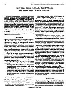
(b) Fig. 3. Definition of the fuzzy input variables: (a) RPM, (b) SOC.
where 0 ≤ Kacc (SOC, RPM) ≤ 1 represents the fraction of torque request for the electric motor as a function of the instantaneous SOC level SOC and the ICE crank speed RPM. When Kacc(SOC, RPM) = 0 all the driver request is assigned to the ICE. Conversely, when Kacc (SOC, RPM) = 1 all the driver request is assigned to the EM. From a different point of view equations (1) can be interpreted by saying that the driver choses the time evolution of the acceleration through the signal adriver, whereas the PTM algorithm chose the split of the request between the engines through the signals SOC and RPM. A similar approach is followed for the deceleration phase where the accelerator signal is replaced by the brake signal and the driver request is split between regenerative braking and traditional dissipative mechanical braking through the coefficient Kbrk(SOC, RPM). In this paper the mapping of SOC and RPM into Kacc(SOC, RPM) is realized through fuzzy logic technique. As shown in Fig. 3 both the input variables have been split into three fuzzy ranges. The Kacc is considered LOW, MED or HIG when it is lower than 30 [%], between 30 and 80 [%] or higher than 80 [%], respectively. The RPM is considered LOW, MED or HIG when it is lower than 1000 [rpm], between 1500 and 4500 [rpm] or higher than 4750 [rpm], respectively. This definition is based on the idea to keep ICE fuel consumption under 200 [g/HPh] in the MED range. The SOC is considered LOW, MED or HIG when it is lower than 30 [%], between 40 and 60 [%] or higher than 80 [%], respectively. The output variable Kacc is fuzzyfied in each of the three ranges as shown in Fig. 4.
Fig. 4. Definition of the fuzzy output variable Kacc.
The fuzzy rules used to build the mapping between SOC and RPM antecedents and Kacc consequent are listed in TABLE I. TABLE I: RULES FOR THE ACCELERATION CASE
If SOC ∈ HIG and RPM ∈ LOW then EMACC ∈ HIG If SOC ∈ HIG and RPM ∈ MED then EMACC ∈ MED If SOC ∈ HIG and RPM ∈ HIG then EMACC ∈ HIG If SOC ∈ MED and RPM ∈ LOW then EMACC ∈ HIG If SOC ∈ MED and RPM ∈ MED then EMACC ∈ LOW If SOC ∈ MED and RPM ∈ HIG then EMACC ∈ MED
Similarly the split coefficient active during the deceleration phase Kbrk if fuzzyfied as shown in Fig. 5. The Kacc is considered MED or HIG when it is around 60 [%] or higher than 80 [%], respectively. The fuzzy rules used to build the mapping between SOC and RPM antecedents and Kbrk consequent are listed in TABLE II.
Fig. 5. Definition of the fuzzy output variable Kbrk.
275
International Journal of Computer Theory and Engineering, Vol. 5, No. 2, April 2013 TABLE II: RULES FOR THE DECELERATION CASE
The LabView implementation of the acceleration and deceleration phases is realized by means of an IF structure. When the signal GasPed1 is different from zero it is executed the block Diagram related with the True condition shown in Fig. 7 part (a). In this case the GasPed1 signal encoding the driver request adriver during the acceleration phase is multiplied by the Kacc and the (1-Kacc) coefficients to obtain the signals aEM and aICE, respectively.
If SOC ∈ LOW then EMBRK ∈ HIG If SOC ∈ MED then EMBRK ∈ MED
IV. LABVIEW IMPLEMENTATION In this section is discussed and examined the LabView implementation of the software (SW) running on the PTM unit. It is constituted of two main parts: the Software/Hardware interface and the power train algorithm described in Section III. The code written with LabView, called Virtual Instruments (VI), is composed of two parts: the Front Panel which is the user interface and the Block Diagram which is the graphical source code. The present project is composed of 2 VIs communicating between them. The first VI, running on the FPGA chip, is called ReadWrite, whereas the second, running on the real time processor, is called MainRt. The ReadWrite VI manages the read and write operations for all the 4 I/O modules installed on the CRIO. The MainRt VI is used to elaborate and display signals from I/O modules and CAN Bus. The Block Diagram portion of the MainRt VI is composed of a While Loop structure, timed at 100 ms, which runs continuously. In the body of the loop there is a Case structure which allows the conditional execution of three different sub diagrams depending on the value assumed by a control variable. Each of these three sub-diagrams correspond to one of the three different states listed below: Init - all the ports are initialized Acq - signals are acquired, processed and displayed Exit - an internal or an external condition causes the end of all process Each time the VI is executed it starts in the Init state. After initialization process, the controller moves in the Acq state until the exit condition occurs. A portion of the Block Diagram of the MainRt VI is shown in Fig. 6, where the two blocks on the left and on the right are used to realize the communication between the ReadWrite VI, running on the FPGA chip, and the MainRt VI for the input and the output, respectively. In the frame labeled „Power Train Algorithm‟ it is implemented the PTM algorithm that makes use of the fuzzy logic described in Section III. The PTM algorithm uses the RPM, SOC and adriver signals to calculate the split coefficient Kacc between the EM and the ICE during the acceleration phase. Similarly, during the deceleration phase, the PTM algorithm uses the RPM, SOC and the brake signals to calculate the entity of the regenerative braking Kbrk.
(a)
(b)
Fig. 7. IF structure of the MainRt VI: (a) acceleration phase, (b) deceleration phase.
These signals are then mapped into Acc1, Acc2 and IceLoad1, IceLoad2 signals after a suitable scaling needed to match the voltage range of the physical devices. Similarly, when the GasPed1 signal is equal to zero it is executed the block Diagram related with the False condition shown in Fig. 7 part (b). In this case the Brkprs signal that represents the driver request during the deceleration phase is multiplied by the Kbrk coefficient to obtain the signal aEM, needed to drive the electric machine during the regenerative braking, which acts in addition to the traditional dissipative braking system. If the resulting deceleration is too high, the driver will decrease the braking pressure. In this case the aICE signal is set equal to zero. The implementation of the fuzzy logic described in Section III was achieved by using a tool of LabView called „Fuzzy System Designer‟. It was used „Sigmoid‟ Membership Function (MF) and a „Center of area‟ defuzzyfication technique.
V. FINAL COMMENTS The Kacc(SOC, RPM) surface obtained by implementing the fuzzy logic described in Section III with the LabView „Fuzzy System Designer‟ is shown in Fig. 8. Observing the figure a few comments can be made. First, it can be noted that the EM contribution to the propulsion is zero when the SOC level is lower than 30%. This feature protects the ESS from under voltage condition that can be very dangerous when Lithium batteries are used. Second, the EM is used at full power in two situations. The first condition is verified when the SOC level is higher than 30% and simultaneously the speed of the crank shaft is lower than about 1500~[rpm]. In This situation the EM is used to move the vehicle at low speed where the ICE has very low performances. Additionally the EM is deeply used when the SOC level is higher that 80% and an high speed is required. Third, the contribution of the EM to the traction is moderate when the ICE is in its maximum efficiency range.
Fig. 6. Definition of the fuzzy output variable Kbrk.
276
International Journal of Computer Theory and Engineering, Vol. 5, No. 2, April 2013
ACKNOWLEDGMENT The authors wish to thank “Robotronix Robotics and Automation” for providing the CRIO hardware and for their useful suggestions during the implementation phase. REFERENCES [1]
[2]
[3]
[4]
Fig. 8. LabView implementation of Kacc(SOC, RPM). [5]
The Kbrk(SOC, RPM) surface obtained by implementing the fuzzy logic described in Section III with the LabView „Fuzzy System Designer‟ is shown in Fig. 9. Looking at this figure it is possible to make the following comments. First, as expected, the only relevant input is the SOC level, in fact there is no modulation along the RPM variable. Second, the regenerative breaking is disabled when the SOC level is higher than 80%. This feature is needed to protect the ESS from extra charge which can result in a device failure or even in causing the explosion of the device. Conversely, when the SOC level is lower than about 25% an intensive electromechanical recharge is performed.
[6]
[7]
[8]
C. Boccaletti, G. Fabbri, F. M. F. Mascioli, and E. Santini, “Technical and economical feasibility study of a small hybrid vehicle for urban transportation” in Proc. of 1st Workshop on Hybrid and Solar Vehicles, Salerno, Italy, 2006, pp. 57-62. C. Lee, “Fuzzy logic in control systems: Fuzzy logic controller. Part i,” IEEE Transactions on Systems, Man and Cybernetics, vol. 20, no. 2, pp. 404-418, 1990. C. Lee, “Fuzzy logic in control systems: Fuzzy logic controller. Part ii,” IEEE Transactions on Systems, Man and Cybernetics, vol. 20, no. 2, pp. 419-435, 1990. M. Panella, A. Rizzi, F. M. F. Mascioli, and G. Martinelli, “Anfis synthesis by hyperplane clustering,” in Proceedings of Joint International Fuzzy System Association World Congress and North American Fuzzy Information Processing Society International Conference (IFSA/NAFIPS 2001) Vancouver, Canada, vol. 1, pp. 340-345, 2001. N. Schouten, M. Salman, and N. Kheir, “Fuzzy logic control for parallel hybrid vehicles,” IEEE Transactions on Control Systems Technology, vol. 10, no. 3, pp. 460-468, 2002. F. Khoucha, M. Benbouzid, and A. Kheloui, “An optimal fuzzy logic power sharing strategy for parallel hybrid electric vehicles,” in Proceeding of IEEE Vehicle Power and Propulsion Conference (VPPC), 2010, pp. 1 5. EUCAR Traction Battery Group, High Voltage HEV Traction Battery Test. Procedure, Draft, April 2004. [Online]. Available: http://kokamamerica.com/kokam catalog.pdf M. Paschero, G. Del Vescovo, A. Rizzi, and F. M. F. Mascioli, “An embedded computer based system for monitoring diagnostic and communication in hybrid and electric vehicles,” in Proceeding of EVS09, 2009
Maurizio Paschero is a post doctoral research associate at the Dipartimento di Ingegneria dell'Informazione, Elettronica e Telecomunicazioni (DIET) of the University of Rome "La Sapienza" since September 2008, where he works in the Polo per la Mobilità Sostenibile (POMOS) Laboratories. He received the Laurea degree in Electronics Engineering in July 2003 and the Ph.D in Information and Communication Engineering in May 2006 from the University "La Sapienza" of Rome and the Ph.D in Mechanical Engineering in March 2008 from Virginia Polytechnic Institute and State University. His major fields of interest include circuital modeling of multi-physic systems, intelligent signal processing, control of hybrid powertrains, smart structures, stability of structures.
Gian Luca Storti attended the Faculty of Electronics Engineering at "Sapienza" University of Rome, and received the Laurea degree in January 2011 with a thesis entitled "Design and production of power, transmission data and service electrical system on parallel hybrid vehicle", developed with the collaboration of the Polo per la Mobilità Sostenibile (POMOS). In November 2011, he began the Ph.D in Information and Communication Engineering at the University "Sapienza" of Rome. His major fields of interest include Smart Grids, intelligent signal processing, modelling and control of hybrid powertrains, design of automotive electrical system.
Fig. 8. LabView implementation of Kbrk(SOC, RPM).
For intermediate level of SOC regenerative braking is achieved with about one half of the available power. Based on the previous comments, it can be stated that the controller behaves as expected. However, in order to improve the handling and the drivability of the vehicle it is mandatory to test the proposed controller on the real vehicle.
277
International Journal of Computer Theory and Engineering, Vol. 5, No. 2, April 2013 Mobility Pole of Lazio Region. He is author of more than 60 publications.
Antonello Rizzi received the Dr. Eng. degree in Electronic Engineering from the University of Rome "La Sapienza" in 1995 and the Ph.D in Information and Communication Engineering in 2000, from the same University. In September 2000 he joined the "Information and Communication" Department (INFO-COM Dpt.) of the University of Rome "La Sapienza" as an Assistant Professor. Since July 2010 he joined the Department of "Information, Electronics and Telecommunications Engineering" Department, in the same University. His major fields of interest are in the area of Soft Computing, Pattern Recognition and Computational Intelligence, including supervised and unsupervised data driven modelling techniques, neural networks, fuzzy systems and evolutionary algorithms. His research activity concerns the design of automatic modelling systems, with particular emphasis on classification, clustering, function approximation and prediction problems. In particular, he is currently working on classification and clustering systems for structured patterns, graph matching, symbolic inductive modelling systems, Granular Computing and Knowledge Discovery systems. Since 2008, he serves as the scientific and technical coordinator of the R&D activities in the Intelligent Systems Laboratory within the Sustainable
Fabio Massimo Frattale Mascioli was born in Rome, Italy, on June 13, 1963. He received the Laurea degree in Electronic Engineering in 1989 and the Ph.D. degree in Information and Communication Engineering in 1995 from the University "La Sapienza" of Rome. In 1996, he joined the DIET Department (ex INFOCOM) of the University "La Sapienza" of Rome as Assistant Professor (Researcher). Since 2000, he has been Associate Professor of Circuit Theory at the same department. His research interest mainly regards neural networks and neuro-fuzzy systems and their applications to clustering, classification and function approximation problems. Currently, he is also working on circuit modelling for vibration damping, energy conversion systems, electric and hybrid vehicles, energy-mobility integrated systems. He is author or co-author of more than eighty papers presented at international conferences or published in international scientific literature. Since 2007, he is the scientific director of the "Polo per la Mobilità Sostenibile della Regione Lazio" (Sustainable Mobility Pole of Lazio Region).
278