Implementation of Resilient Packet Ring Nodes Using Network Processors Andreas Kirstädter, Member, IEEE, Axel Hof, Siemens AG, Corporate Technology Walter Meyer, Erwin Wolf, Siemens AG, ICN
[email protected] Siemens AG, Corporate Technology Information and Communications Otto-Hahn-Ring 6 81730 München, Germany
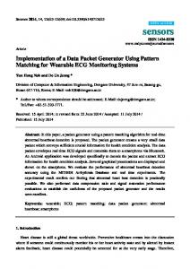
Abstract Network processors offer a new flexibility for network applications and reduce the time to market for data processing systems. In this paper, we describe the changed development process of the data plane using the Motorola C-5 Network Processor. We implemented a Resilient Packet Ring line card for a SDH cross connect. We show a solution for the support of different Quality of Service classes with a Network Processor and to achieve the necessary system stability. Additionally we carried out some simulations to verify the performance of a fairness algorithm over the ring and the system behavior. Keywords—Network processors, High-speed LAN, Quality of Service, Simulation 1. Introduction The Resilient Packet Ring (RPR) is a draft standard to transport data traffic over a ring-based media with data rates scalable to many gigabits per second in Local or Wide Area Networks [1,2]. Two counter-rotating bufferinsertion rings constitute a RPR, as shown in Figure 1.
Figure 1: RPR topology on the basis of SDH links.
The Institute of Electrical and Electronic Engineers (IEEE) began the RPR standards (IEEE 802.17) development project in December 2000 with the intention to create a new Media Access Control layer for RPR. A RPR is a ring architecture that consists of packetswitching nodes connected to adjacent nodes via a fiber pair. The link bit-rate of an RPR can take values in the range from 155 Mbit/s up to 10 Gbit/s [2]. Among many deployment areas RPRs are especially attractive for the use within (optical) SDH Add-Drop Multiplexer in Metropolitan Area networks. SDH paths constitute the links between the RPR nodes. Our implementation of RPR is located on a line card within an Add-Drop Multiplexer allowing the transparent transport of Ethernet Packets over the SDH ring. The operator may run this card using four different configurations. On the tributary interface side the card offers the choice between 10/100Mbps and 1 Gbbps Ethernet. On the (SDH) ring side either VC-4 paths or VC-4-4v paths can be supported. To achieve this flexibility, a network processor (NP) was selected for the task of data processing [3]: The single link options can be activated via simple software download on the basis of the same hardware Another reason for the use of a network processor is the still open standard and any changes can be easily adapted in a following release by changing only the SW but using the same hardware platform The development of the RPR card was our first project with a network processor. Before the start of the card development we investigated different implementation options wthin a small evaluation project. After a technology scan of the available network processor the C5 from C-Port/Motorola seemed to be appropriate for this kind of application [4]. The use of network processor made changes in the development process necessary. The rest of the paper is organized as follows: Chapter 2 describes the architecture of the RPR card and the SDH Add Drop Multiplexer it is connected to. Chapter 3 gives a small overview of the C-5 network processor and the main features of the processor. The changes in the development process and the problems overcome with the network processor are presented in chapter 4.
Additionally, we carried out some system simulations of the RPR ring. Chapter 5 describes the simulator and presents various results of the system simulation. 2. RPR card and the SDH multiplexer The SDH Add Drop Multiplexer is a multi service system and is configured in a rack with multiple flavors of line cards. A SDH back plane provides the interworking among the cards across a switch fabric and a control processor card manages the operation of the system. The line cards of the system run with OC-3, OC-12 and OC48.
instruction memory of 24 kByte that also can be divided so that each CP gets a dedicated 6kByte sub-array. The C-5 NP contains three independent data buses that provide internal communication paths between the C-5 NP’s eighteen processors. The Payload Bus uses a 128bit wide data path in four-cycle bursts to transfer up to 64 Bytes of payload data. The C-5 NP implements a ringtopology bus for communication between the TLU and the eighteen processors The Global Bus provides direct access to most C-5 NP memory space.
A host processor controls the network processor. It consists of a Power PC processor connected via a PCI bridge to the network processor. The host processor takes care about the generation of the routing table, the alarm handling and bandwidth reservation. Via the PCI bridge the host processor can access a part of the data memory of the NP, e.g. for downloading routing tables to the NP or reading of some statistical data. A control processor core (XP) within the NP handles the access of the host processor to the data memory. Figure 3: C-5 NP architecture
Figure 2: Architecture of RPR line line 3. Network Processor The C-5 network processor from Motorola contains 16 parallel channel processors. They consist of a RISC core together with a Serial Data Processor SDP) for the bit and byte processing [5]. Additionally there are 5 special units on the C-5 for the buffering and queuing, , another unit for table lookups (TLU), a fabric processor (FP) and a control processor (XP), see Figure 3. The 16 parallel channel processors (CP) are ordered into 4 clusters of 4 processors each. The 4 processors in one cluster can run the same application and share an
Each of the sixteen CPs contains a Reduced Instruction Set Computer (RISC) Core. The dedicated RISC Core in each channel controls cell and packet processing and executes a MIPS TM 1 instruction set (excluding multiply, divide, floating point). Two extra units of the C-5 NP manage packet buffering and queuing.. The payload of the incoming packet is stored in the external memory, which is controlled by the Buffer Management Unit (BMU). The BMU controls the storage of the payload and returns a descriptor of the memory block for the payload storage to the CP. After the lookup at the Table Lookup Unit (TLU) the CP sends the descriptor of the payload buffer to the Queue Management Unit (QMU) and enqueues it into the queue of the transmitting CP. For the communication with the QMU, BMU and TLU exists a library of service functions [6] that is used by the code running on the CPs. The library functions, example applications, and the complete tool environment are part of the C-Ware Software Toolset (CST). There exist different releases of the CST and the code can be ported from one release to the other. The Executive Processor (XP) also executes the library functions. The XP, being the only processor with no linkage to the data path, controls the operation of the other processors and downloads the configuration onto them and the special units. During runtime the XP generates control messages or table entries within the TLU.
3.1. Aggregation Mode For higher data rates the channel processors of one cluster on the C-5 NP may run in an aggregated mode: The channel processors work in parallel on the same data interface and the data stream of one input is multiplexed on the four channels in a round robin fashion. The CPs work in a pipelined manner. To guarantee the correct order of the packets the processors are synchronized by hardware tokens (see Figure 4).
Figure 4: 4 SDPs of one cluster in aggregation mode The parallel working CPs share common resources like queues and variables. If the processor accesses a variable only once and in a synchronized order, the access can be controlled with a hardware token. The exchange with the QMU (add or remove descriptor from a queue) is also synchronized by the token to avoid packet reordering. The access time to some of the internal variables is not predictable. Therefore the access to these variables has to be checked with a semaphore that at the same time slows down the access time to the variable. Thus it is desirable to limit the number of semaphores used. The support of Quality of Service (QoS, in the sense of packet stream transmission orders at the output ports of the NP) gets more time critical in the aggregated mode. For QoS the processor has to serve a number of queues having different priorities. The RPR application manages up to 11 queues in a top-down priority and round robin scheme. To decide, which queue has to be served next the channel processor needs status information about all queues. In the aggregated mode the following synchronized steps have to be performed at the transmission context for the selection of a packet : − The processor has to decide from which queue it takes the next packet descriptor.
−
The processor initiates the transfer of the packet descriptor from the QMU to the CP. − The CP reads out the status information of the received message from the QMU via the descriptor and updates the status information of the served queue. For the decision about the next packet the CP needs the current status information of the queue. Another processor is reading out a descriptor from the queue in parallel. Therefore the access to the queue status information has to be synchronized. The service library of the QMU provides two possibilities for obtaining queue status information. One function delivers the number of descriptors in the queue and the other gives back a bit vector with information of all queues of a CP. The 0 symbolizes an empty queue and a 1 a filled queue. With the information of the exact fill level of the queue the CP has to check for an increasing number of queues (in the worst case a lot of queues) until it knows from which queue to take the next descriptor. Therefore, the CP consumes less clock cycles with the bit vector of the information about all queues because the CP has to access the QMU only once. But the CP gets the right fill level of the queue not until it receives the message with the descriptor of the payload. Therefore the bookkeeping with the number of descriptors within a queue has to take the parallel access of the other CPs into account. We found an algorithm with an equal execution time of the three synchronized code blocks. 3.2. Performance Limitations
Estimation
and
Processor
The C-5 tool environment includes a cycle-accurate simulator together with a performance analyzer. For performance analyzing trace points have to be inserted into the code. Time consuming code segments can be detected easily by measuring clock cycles between these trace points.. For each of them it stores the cycle count and the passed trace points in a data file. With this tool we made a first rough estimation of the workload on the processor. The main problem for the building of the application was the limited instruction memory (IMEM). Each CP provides an IMEM of 6 kByte. In a cluster of 4 CPs, where each CP runs the same task, the CPs can share their IMEMs. So there are 24 kByte available for the application.. In an early stage of the development process we reached the limit of the IMEM. Limitation of instruction memory space was one of the major challenges of the project. Code reduction was a solution:. The compiler links unused library service functions to the execution code. By stripping off unused library functions we were able to free 1 kByte of IMEM.
Unfortunately the absence of library functions may cause unpredictable behavior of the application. Performance is another crucial point in a network processor environment. We found different means for tuning the code. With the help of the performance analyzer we investigated the time budget for every code segment. The optimization experiences can be summarized in the following hints: − avoid “FOR”-loops − use a pointer instead of an array index if the same index is used more than one time − use hardware semaphores (ksToken) instead of software semaphores (ksMutex) − use inline functions − use branches (goto) to jump over unnecessary statements − substitute library function calls with direct register access (not portable!) Some of the optimization steps consumes more IMEM like the use of inline functions or makes the code “difficult to read”. Additional you have to keep in mind that modification of the library code will generate problems with each new CST release. 3.3. Queue Overflows A serious problem for the network processor is a queue overflow or if a channel processor accesses an empty queue. In both cases the QMU sends an interrupt towards the accessing channel processor. The channel processor has to handle this interrupt. For every registered interrupt exists an interrupt routine to clean up all allocated resources that are no longer needed because of the failure. An interrupt is very time critical for the channel processor. Each interrupt means a context switch and the processor first has to store the context, before the processor can access variables, which are used in the previous context. Save and restore of a context is very time consuming. The processor needs about 300 to 400 cycles for these two operations in the reference code. Therefore it is more efficient to have very simple interrupt routines. One solution is just to signal by an indicator, that the interrupt has occurred. The indicator can be checked in any active context in a polling manner. For the RPR we have two types of packets transmitted over the ring. Data packets, which are the majority, and control packets for the generation of the routing table, for alarming and control and distribution of the available ring bandwidth. If a queue overflow in system occurs very rarely the interrupt can be handled with an interrupt routine. Within the interrupt routine the processor has to free the allocated buffer and to prepare all variables for the arrival of the next packet. If overflows are very likely and the system has different kind of packets, the interrupt
routine gets more complex and insecure. Insecure moments may arise when the processor is already processing the next packet and receives the interrupt from the last packet. The processor frees the previous buffer and the previous buffer is ignored. This leads to a memory leak and after a number of queue overflow the system runs out of buffer descriptors. For a large rate of queue overflows the system becomes more stable when the processor counts the number of enqueued packets or even better gets the fill level of the queue. If the queue becomes nearly full the processor stops to enqueue the packets and drops them. Checking the queue fill level costs some extra clock cycles for each packet and decreases the system performance. If the queue belongs to another CP the CP has to communicate with QMU to get the fill level costing some additional clock cycles. But the CP only has to check the fill level when the number of enqueued packets gets close to queue limit and can update the local variable with the number of packets in the queue. 4. System test In an NP based system test and also development process of the application differs from previous projects. The target hardware was already available in an early state of the implementation process. In a first step we had to test the correct behavior of all interfaces to the network processor. At this time the final application software for the NP and the host processor was not available. We therefore used a simple application software on the NP for each interface which was only able to loop back the incoming traffic to itself (either in the SDP or in the CPs). For the test of the special units some diagnostic software is part of the C-5 environment. In parallel to the implementation of the application software we ran some tests on the simulator and the target hardware. The C-5 NP simulator within the development environment uses Perl scripts to generate traffic patterns. These traffic patterns stimulate the simulator. With this traffic patterns we were able to simulate the principal behavior of the system using only few packets (some 100 to 1000 packets). In parallel we made some similar tests with the target hardware stimulated by a traffic generator (millions of packets). Typical misbehavior of the system was: − Loss of traffic flow − Shut down of a CP The loss of traffic flow indicates the absence of a system resource like a descriptor of a packet or a buffer block for the payload. The trace functions of the C-5 NP simulator show such a kind of memory leak but sometimes this occurs after a few thousands of packets. Therefore we changed the interrupt routine for the absence of system resources and just signaled the occurrence of such an
error. The system is not able to handle this error and for long time stability these kind of error is unacceptable. Writing out information to a console window during packet processing is not practical, because the print function itself consumes performance of the processor and packet processing is no longer possible with line speed. The only way to get some information from the processor during data processing with line speed is the insertion of some additional variables. These variables can be accessed from the host processor via the PCI bridge. Due to the nature of the packet processing the processor does busy waiting for the next packet and then performs same routines for each packet. Therefore the application code includes often while loops. These while loops are a second reason for a deadlock of the CP and a loss of traffic flows. E.g. if the CP misses a response of the TLU the processor stops and waits for the response. A timeout function in every while loop or the attaching with the debugger of the C-5 development environment helped us to find a stop of the program due to that kind of error. If the CP gets an unregistered interrupt or has no interrupt routine the processor ends up in a panic mode and stops working. But every interrupt has information about the sending device and the kind of error occurred. The print out of all the available information of the interrupt indicates the reason for the error. Due to the limited instruction memory we encountered problems in adding additional code like the timeout functions to the application. Therefore, we had to skip a part of the code for the tests or we had to change the code. The NP code for the RPR application is not complex and has about 10000 lines of code. The dependencies between different parts of the code are the challenge during the system test. A change in one part of the code can have a side effect to other parts of the code. Therefore a lot of reiterations were necessary. During the system test various changes in the design - like the handling of a queue overflow - were required. These changes always bear a high risk for new errors with them. System simulations are very helpful for the verification of the fairness algorithm. With a simulator it is easy to observe single variables and the whole system behavior can be optimized. It is more easy to find and locate errors during simulation than in the real system and a set of different parameters can be simulated within a short period of time. 5. System Simulations For the RPR card a simulator was developed to model the protocol running on the ring. With this simulator the behavior and most diverse performance investigations can be accomplished.
The simulator is programmed in C++; the libraries of CNCL (Communication Networks Class Library [8]) were used. It works event based and is built in a very modular manner. The protocol and also the simulator are specially adapted to the behavior of the C-5- NP. To simulate different scenarios it is possible to use different sources with different distributions of packet length and destination addresses. To accomplish the behavior and performance investigations of the protocol, meters can be attached to points of interest in the investigated network. They collect data while the simulation is running. As an example the following drawings show the priority handling in an eight-node topology where first node #4 at time=0sec sources 100 Mbps of low-priority traffic onto the ring (link capacity: 150 Mbps) for forwarding further downstream towards node #6 (see Figure 5). At the time=0.5sec node #5 sources 100 Mbps of high-priority traffic also destined to node #6.
Figure 5: Eight node network with traffic meter Figure 6shows the resulting throughput in the form of forwarded low-priority traffic originated by node #4. And Figure 7shows the amount of traffic sourced by node#5.
6. Conclusion Despite of many problems during implementation, we successfully finished the project and since some month the system is delivered to customers. We gained a lot of experience in programming network processors and to summarize it up: the team enjoyed the work in this project. 7. References [1] IEEE 802.17 Resilient Packet Ring Working Group Website, http://www.ieee802.org/rprsg/.
Figure 6: Throughput from node #4 over time
Figure 7: Throughput from node #5 over time As it can be seen from the diagrams above the ring fairness protocol preserves the strict priority between high and low-priority traffic. Exactly the same result was also measured in the experimental setup.
[2] H.R. van As, “Overview of the Evolving Standard IEEE 802.17 Resilient Packet Ring,” 7th European Conference on Networks & Optical Communications (NOC), Darmstadt, Germany, June 18-21, 2002. [3] T. Wolf, “Design of an Instruction Set for Modular Network Processors,” IBM Research Report, RC 21865, October 27, 2000 [4] N. Shah, “Understanding Network Processors,” Master’s Thesis, Dept of Electrical Engineering and Computer Science, Univ. of California, Berkeley, 2001 [5] C-5e Network Processor Architecture Guide Silicon Revision A0, Motorola, http://ewww.motorola.com/brdata/PDFDB/docs/C5EC3EARCHRM.pdf [6] C-5e Application Documentation, Motorola, http://ewww.motorola.com/webapp/sps/site/prod_summary.jsp?c ode=C-5E#applications [7] QMU Configuration and RC Support, Motorola, http://ewww.motorola.com/brdata/PDFDB/docs/CSTCQRC S-UG.pdf [8] RWTH Aachen, http://www.comnets.rwthaachen.de/doc/cncl/