Sep 23, 2016 - This thesis provides a systems engineering method for complex and demanding ...... Redmine includes a ticketing principle through which tasks can be ...... logging. The mass and volume budgets on the other hand were ...
Lehrstuhl für Raumfahrttechnik Prof. Prof. h.c. Dr. Dr. h.c. Ulrich Walter
Technische Universität München
Implementation of Systems Engineering Methods in a Running Volunteer Project At the Example of MOVE-II LRT-SA 2016/XX Authors: Kim Hannah Steinkirchner Florian Schummer
Betreuer:
Christian Bühler Lehrstuhl für Raumfahrttechnik / Institute of Astronautics Technische Universität München
Kim Hannah Steinkirchner, Florian Schummer
Acknowledgments First of all we want to thank Prof. Prof. h.c. Dr. Dr. h.c. Ulrich Walter for the possibility to write such a thesis at the Institute for Astronautics, and the whole institute for their unique openness and willingness to help wherever and whenever necessary. Special thanks also goes to our advisors and mentors Christian Bühler and Dr. Ing. Markus Brandstätter. Their expertise, council and unique perspective guided us in the right direction, and the open and free discussions were not only a delight but also an encouragement for us. For the advancement of trust and the eager cooperation from the very first moment on, we thank the whole MOVE team, but especially Martin Langer and Nicolas Appel. Our work at the MOVE-II project is the foundation of all work that is presented here, and without the freedom and responsibility we were granted by them this would never have been possible.
page II
Kim Hannah Steinkirchner, Florian Schummer
Zusammenfassung Die vorliegende Arbeit beschäftigt sich mit einer systemtechnischen Methode zum Umgang mit komplexen und herausfordernden Entwicklungsprojekten auf Freiwilligenbasis. Die Methode ist anwendbar auf eine Vielzahl von technischen Entwicklungsprojekten. Für den Fall der Applikation in einer späteren Projektphase werden die notwendigen Anpassungen diskutiert und auftretende Effekte berücksichtigt. Des weiteren liegt der Fokus der Arbeit auf der Optimierung des Entwicklungsprozesses um maximale Effizienz und Effektivität des freiwilligen Entwicklerteams zu gewährleisten. Die Arbeit ist in die folgenden Punkte unterteilt: • Reviews • Concept of Operations • Requirements engineering • Bewertung technischer Budgets • Teambuilding • Schnittstellen • Kommunikation • Management Unterstützung Die beschriebenen Werkzeuge und Methoden wurden in der CubeSat Entwicklung MOVE-II am Lehrstuhl für Raumfahrttechnik der Technischen Universität München angewandt.
page III
Kim Hannah Steinkirchner, Florian Schummer
Abstract This thesis provides a systems engineering method for complex and demanding engineering projects, that are based on volunteer contribution. The method is applicable to a wide scope of technical development projects. It shall also be applicable if introduced in a later project phase. The necessary adjustments to apply the method in a later phase are discussed and the occurring effects are considered. A special focus is set on optimizing the development process to achieve a maximum in effectiveness and efficiency of the volunteer development team. The thesis is divided in and covers the following topics: • Reviews • Concept of operations • Requirements engineering • Assessment of technical budgets • Team building • Interfaces • Communication • Management distribution All described tools and processes were applied on the CubeSat development project MOVE-II of the Institute for Astronautics at the Technical University of Munich.
page IV
Kim Hannah Steinkirchner, Florian Schummer
Contents
1 Overview 1.1 Motivation . . . . . . . . . . . . . . . . . . . . . . . . . . . . . . . 1.2 Systems Engineering . . . . . . . . . . . . . . . . . . . . . . . . . 1.2.1 Team Building . . . . . . . . . . . . . . . . . . . . . . . . . 1.2.2 Communication . . . . . . . . . . . . . . . . . . . . . . . . 1.2.3 Management Distribution . . . . . . . . . . . . . . . . . . 1.2.4 Interface Management . . . . . . . . . . . . . . . . . . . . 1.2.5 Technical Budgets . . . . . . . . . . . . . . . . . . . . . . 1.2.6 Concept of Operations . . . . . . . . . . . . . . . . . . . . 1.2.7 Requirements Engineering . . . . . . . . . . . . . . . . . 1.3 Technological Description of MOVE-II . . . . . . . . . . . . . . . 1.3.1 Nanosatellites and CubeSats as Revolution in Space Technology Development . . . . . . . . . . . . . . . . . . . . . 1.3.2 Mission Goal . . . . . . . . . . . . . . . . . . . . . . . . . 1.3.3 MOVE-II State of the Art March 2016 . . . . . . . . . . . . 1.4 Social Description of MOVE-II . . . . . . . . . . . . . . . . . . . . 1.4.1 Organization . . . . . . . . . . . . . . . . . . . . . . . . . 1.4.2 Challenges Provided by the Student Based Project Character . . . . . . . . . . . . . . . . . . . . . . . . . . . . . . 1.5 Document Structure . . . . . . . . . . . . . . . . . . . . . . . . .
8 10
2 Team Building 2.1 The Need for Team Building . . . . 2.2 Team Building Methods . . . . . . 2.2.1 Organizational Chart . . . . 2.2.2 Semester Start Workshops 2.2.3 Informal Meetings . . . . . 2.3 Implementation in MOVE-II . . . . 2.3.1 Situation . . . . . . . . . . . 2.3.2 Implementation . . . . . . . 2.4 Conclusion . . . . . . . . . . . . .
. . . . . . . . .
11 11 12 12 13 13 14 14 14 17
3 Reviews 3.1 Reviews as Means for Project Development and Fault Detection . 3.2 Supporting Methods for the Conduction of Reviews . . . . . . . . 3.2.1 Correction Cycle . . . . . . . . . . . . . . . . . . . . . . . 3.2.2 Document Layout . . . . . . . . . . . . . . . . . . . . . . . 3.2.3 Supporting Documents . . . . . . . . . . . . . . . . . . . .
18 18 19 19 19 20
. . . . . . . . .
. . . . . . . . .
. . . . . . . . .
. . . . . . . . .
. . . . . . . . .
. . . . . . . . .
. . . . . . . . .
. . . . . . . . .
. . . . . . . . .
. . . . . . . . .
. . . . . . . . .
. . . . . . . . .
. . . . . . . . .
. . . . . . . . .
. . . . . . . . .
. . . . . . . . .
1 1 1 2 2 2 3 3 3 3 4 4 4 5 5 5
page V
Contents 3.2.4 Versioning in Git . . . . . . 3.3 Implementation in MOVE-II . . . . 3.3.1 Situation . . . . . . . . . . . 3.3.2 Preliminary Design Review 3.3.3 Delta-PDR . . . . . . . . . . 3.3.4 Critical Design Review . . . 3.3.5 Conclusion . . . . . . . . .
. . . . . . .
. . . . . . .
. . . . . . .
. . . . . . .
. . . . . . .
. . . . . . .
. . . . . . .
. . . . . . .
. . . . . . .
. . . . . . .
. . . . . . .
. . . . . . .
. . . . . . .
. . . . . . .
. . . . . . .
. . . . . . .
4 Communication 4.1 Communication Channels . . . . . . . . . . . . . . . . . . . . . 4.2 Communication Principles . . . . . . . . . . . . . . . . . . . . . 4.3 Implementation in MOVE-II . . . . . . . . . . . . . . . . . . . . 4.3.1 Situation . . . . . . . . . . . . . . . . . . . . . . . . . . . 4.3.2 Implementation of Communication Channels in MOVE-II 4.3.3 Implementation of Communication Principles in MOVE-II 4.4 Conclusion . . . . . . . . . . . . . . . . . . . . . . . . . . . . .
. . . . . . .
20 20 20 21 22 23 24
. . . . . . .
25 25 25 26 26 26 27 28
5 Management Distribution 5.1 Project Management Tool . . . . . . . . . . . . . . . . . . . 5.1.1 Functions of Project Management Tools . . . . . . . 5.1.2 Implementation of Redmine as Project Management in MOVE-II . . . . . . . . . . . . . . . . . . . . . . . 5.2 Start-up Package . . . . . . . . . . . . . . . . . . . . . . . . 5.2.1 Contents of a Start-up Package . . . . . . . . . . . . 5.2.2 Start-up Package in MOVE-II . . . . . . . . . . . . . 5.3 Project Plans . . . . . . . . . . . . . . . . . . . . . . . . . . 5.3.1 Methods for Project Planning . . . . . . . . . . . . . 5.3.2 Implementation in MOVE-II . . . . . . . . . . . . . .
. . . . . . Tool . . . . . . . . . . . . . . . . . . . . .
6 Interface Management 6.1 The Difficulty of Interfaces . . . . . . 6.2 Timing . . . . . . . . . . . . . . . . . 6.3 Method for Dealing with Interfaces . 6.3.1 Preparations . . . . . . . . . 6.3.2 Interface Workshop . . . . . . 6.3.3 Post-processing . . . . . . . . 6.4 Implementation in MOVE-II . . . . . 6.4.1 Sidepanel Definition Meetings 6.4.2 Toppanel Definition Meetings
. . . . . . . . .
. . . . . . . . .
. . . . . . . . .
. . . . . . . . .
. . . . . . . . .
. . . . . . . . .
. . . . . . . . .
. . . . . . . . .
. . . . . . . . .
. . . . . . . . .
. . . . . . . . .
. . . . . . . . .
. . . . . . . . .
. . . . . . . . .
. . . . . . . . .
. . . . . . . . .
37 37 37 38 38 39 40 41 42 52
7 Technical Budgets 7.1 Selection of Relevant Budgets . . . 7.2 Budgeting Process . . . . . . . . . 7.2.1 Data Gathering . . . . . . . 7.2.2 Assessment of Data Quality 7.2.3 Derivation of Margins . . . . 7.2.4 Interpretation of Results . .
. . . . . .
. . . . . .
. . . . . .
. . . . . .
. . . . . .
. . . . . .
. . . . . .
. . . . . .
. . . . . .
. . . . . .
. . . . . .
. . . . . .
. . . . . .
. . . . . .
. . . . . .
. . . . . .
55 55 55 56 56 57 57
. . . . . .
29 29 29 29 30 30 30 32 32 33
page VI
Contents 7.2.5 Planning the Next Steps . . 7.3 Further Considerations . . . . . . . 7.3.1 Responsibility . . . . . . . . 7.3.2 Selection of Policy . . . . . 7.3.3 Characterization of Budgets
. . . . .
. . . . .
. . . . .
. . . . .
. . . . .
. . . . .
. . . . .
. . . . .
. . . . .
. . . . .
. . . . .
. . . . .
. . . . .
. . . . .
. . . . .
. . . . .
. . . . .
59 59 59 60 61
8 Concept of Operations 8.1 When to Develop the ConOps . . . . . . . . . . . . 8.2 Scope of the ConOps . . . . . . . . . . . . . . . . 8.3 How to Develop the ConOps . . . . . . . . . . . . . 8.3.1 Choice of Methods . . . . . . . . . . . . . . 8.3.2 Considerations Based on the Project Phase 8.4 Effects on the Project . . . . . . . . . . . . . . . . . 8.4.1 Positive Effects . . . . . . . . . . . . . . . . 8.4.2 Negative Effects . . . . . . . . . . . . . . . 8.5 Conclusion . . . . . . . . . . . . . . . . . . . . . . 8.6 Outlook . . . . . . . . . . . . . . . . . . . . . . . .
. . . . . . . . . .
. . . . . . . . . .
. . . . . . . . . .
. . . . . . . . . .
. . . . . . . . . .
. . . . . . . . . .
. . . . . . . . . .
. . . . . . . . . .
62 62 62 63 63 64 66 66 66 67 67
. . . . . . . . . . . . . . . . . . . . . . . . . . . .
68 68 69 69 69 70 70 70 70 71 71 71 72 72 72 72 72 73 74 75 75 75 76 77 77 77 77 78 78
9 Requirements Engineering 9.1 Chapter Overview . . . . . . . . . . . . . . . . . . 9.2 Goals of the Method . . . . . . . . . . . . . . . . . 9.3 Description of Tools . . . . . . . . . . . . . . . . . 9.3.1 Professional Requirements Software Tools . 9.3.2 SysML req-Diagrams . . . . . . . . . . . . . 9.3.3 Use Cases . . . . . . . . . . . . . . . . . . 9.3.4 Interviews . . . . . . . . . . . . . . . . . . . 9.3.5 Mind Mapping . . . . . . . . . . . . . . . . . 9.3.6 Conceptual Maps . . . . . . . . . . . . . . . 9.3.7 Version Control Software . . . . . . . . . . . 9.4 Assessment of Tools . . . . . . . . . . . . . . . . . 9.4.1 Professional Requirements Software Tools . 9.4.2 SysML req-Diagrams . . . . . . . . . . . . . 9.4.3 Use Cases . . . . . . . . . . . . . . . . . . 9.4.4 Interviews . . . . . . . . . . . . . . . . . . . 9.4.5 Mind Mapping . . . . . . . . . . . . . . . . . 9.4.6 Conceptual Maps . . . . . . . . . . . . . . . 9.4.7 Version Control Software . . . . . . . . . . . 9.5 Selection of Tools . . . . . . . . . . . . . . . . . . . 9.6 Method for Systematic Requirement Reviewing . . 9.6.1 Stakeholder Analysis and Use Cases . . . . 9.6.2 Check Phrasing . . . . . . . . . . . . . . . . 9.6.3 Check Rationales . . . . . . . . . . . . . . . 9.6.4 Trace Requirements . . . . . . . . . . . . . 9.6.5 Update the Visual Model . . . . . . . . . . . 9.6.6 Relation Verification . . . . . . . . . . . . . 9.6.7 Iterations . . . . . . . . . . . . . . . . . . . 9.6.8 Deactivation of Requirements . . . . . . . .
. . . . . . . . . . . . . . . . . . . . . . . . . . . .
. . . . . . . . . . . . . . . . . . . . . . . . . . . .
. . . . . . . . . . . . . . . . . . . . . . . . . . . .
. . . . . . . . . . . . . . . . . . . . . . . . . . . .
. . . . . . . . . . . . . . . . . . . . . . . . . . . .
. . . . . . . . . . . . . . . . . . . . . . . . . . . .
. . . . . . . . . . . . . . . . . . . . . . . . . . . .
page VII
Kim Hannah Steinkirchner, Florian Schummer 9.6.9 Assessment of Requirements Change 9.6.10 Derivation of Performance Values . . . 9.7 Case Study . . . . . . . . . . . . . . . . . . . 9.7.1 Evolution . . . . . . . . . . . . . . . . 9.7.2 Conclusion . . . . . . . . . . . . . . .
. . . . .
. . . . .
. . . . .
. . . . .
. . . . .
. . . . .
. . . . .
. . . . .
. . . . .
. . . . .
. . . . .
78 79 80 82 83
10 Conclusion
85
11 Outlook
86
A Appendix
90
page VIII
Kim Hannah Steinkirchner, Florian Schummer
List of Figures 1.1 Overview over the fields of work in SE . . . . . . . . . . . . . . . 1.2 Organizational Chart MOVE-II, May 5th 2016 . . . . . . . . . . .
2 7
2.1 Information that was inquired for the creation of the organizational chart . . . . . . . . . . . . . . . . . . . . . . . . . . . . . . . . . .
15
5.1 Example WBS of the SE team . . . . . . . . . . . . . . . . . . . . 5.2 Excerpt of the Gantt Chart of the SE team in Redmine . . . . . .
35 36
6.1 The MOVE-II satellite with Side-, Top- and Flappanel . . . . . . . 6.2 bdd of the satellite on top level; used to get an overview of all the parts that are relevant for the Side-, Top- and Flappanel . . . . . 6.3 Interdependency Network between the Sidepanel, Toppanel and Flappanel; the influence between the parts is depicted in arrows with colors (red for high influence, orange for medium influence and green for low influence; the arrows depict who influences whom) . . . . . . . . . . . . . . . . . . . . . . . . . . . . . . . . . 6.4 DSM for the Side-, Top- and Flappanel; influence is depicted by numbers (3 for high influence, 2 for medium, 1 for low, empty fields mean no influence) . . . . . . . . . . . . . . . . . . . . . . 6.5 Influence Portfolio on basis of the DSM; the further a point is on the right side, the more it influences others; the more it is on the top, the more it is influenced . . . . . . . . . . . . . . . . . . . . . 6.6 Distance Matrix for the Side-, Top- and Flappanel; direct influence (3), influence over two parts (2) and influence over tree parts (3) is depicted . . . . . . . . . . . . . . . . . . . . . . . . . . . . . . .
42 47
48
49
50
51
7.1 Budgeting process . . . . . . . . . . . . . . . . . . . . . . . . . . 56 7.2 Exemplary visualization of MOVE-II’s mass budget; inner circle: margin; outer circle: mass including margin divided by subsystems 58 8.1 Example for a Top Level ConOps, for a detailed description refer to [14]. . . . . . . . . . . . . . . . . . . . . . . . . . . . . . . . . .
65
9.1 Screenshot from the version control tool Git; blue circle: all changes are highlighted (dot in the previous version, comma in the current version); green rectangle: in the scroll bar all changes are marked (orange and yellow) . . . . . . . . . . . . . . . . . . . . . . . . . 71 9.2 Exemplary requirements network . . . . . . . . . . . . . . . . . . 74 9.3 Method for Systematic Requirement Reviewing . . . . . . . . . . 76
page IX
List of Figures 9.4 9.5 9.6 9.7 9.8
Focus on the system node . . . . . . . . . . . . . . . . . . . . . . Focus on the requirement SYS-00.1 . . . . . . . . . . . . . . . . Impact on the requirements if Stakeholder1 leaves the project . . Possible impact of a change of directive by Stakeholder2 . . . . . Requirements affected by the change of STEX-DLR-01, concerning the size of the satellite . . . . . . . . . . . . . . . . . . . . . . 9.9 Requirements evolution; green nodes are directly related to the new implemented requirement SYS-00.1 "The MOVE-II satellite shall be controllable during operations" . . . . . . . . . . . . . . .
78 78 79 79 81
83
page X
Kim Hannah Steinkirchner, Florian Schummer
List of Tables 1.1 Comparison of attributes in a company project compared to a volunteer project . . . . . . . . . . . . . . . . . . . . . . . . . . . . .
9
5.1 Overview over the project phases and reviews [20] . . . . . . . .
33
7.1 Margin philosophy (compare [4]) . . . . . . . . . . . . . . . . . .
57
page XI
Kim Hannah Steinkirchner, Florian Schummer
List of Abbreviations ADCS Attitude Determination and Control System AR Acceptance Review bdd Block Definition Diagram CDH Command and Data Handling CDR Critical Design Review CDS CubeSat Design Specification COM Communication System ConOps Concept of Operations DLR German Aerospace Center DSM Design Structure Matrix EDI External Debug Interface EEPC Evolved Event-triggered Process Chains EPS Electric Power System ESA European Space Agency eSMARD evolved Shape Memory Alloy Reusable Deployment Mechanism LRT Institute for Astronautics MDR Mission Definition Review MOVE Munich Orbital Verification Experiment MOVE-II Munich Orbital Verification Experiment II PCB Printed Circuit Board PDR Preliminary Design Review PL Payload PRR Preliminary Requirements Review SDR System Definition Review SRR System Requirements Review
page XII
Kim Hannah Steinkirchner, Florian Schummer SE systems engineering STEX Stakeholder Expectation STR Structure THM Thermal TUM Technical University of Munich uc use case VCS Version Control Software WBS Work Breakdown Structure 1U One Unit
page XIII
Overview
1. Overview This chapter gives an overview of the environment in which this thesis came into being, and the topics that are covered in the thesis. First, the underlying motivation is given. Next, a state of the art in systems engineering (SE) is provided and after that a technological description of the project, on which the thesis is based. The technological description is followed by a social description of the engineering team, because of its large impact on the methods being inspected. At the end of the chapter an overview of the document is given.
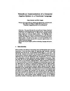
1.1. Motivation SE is a central part of complex development projects. From the very beginning of the discipline in the 1940s, methods were used to document certain patterns of work to cope with the complexity of a system engineer’s tasks and its high impact on a project [1]. In the description of these methods, typically a professional environment and an application of SE from the very beginning of the project are assumed. In general these methods and tools should also be applicable to projects that are based on volunteer contribution, like educational projects with participation of student work groups at universities. Therefore they may have to be adjusted and preselected to fit this environment. The project Munich Orbital Verification Experiment II (MOVE-II) provides an ideal environment to assess SE methods and develop an overall method for SE work in such an environment.
1.2. Systems Engineering "System engineering is the art and science of developing an operable system capable of meeting requirements within imposed constraints." [2] SE is the name of a discipline that deals with the coordination of development tasks, with the goals to ensure the cost efficiency, the schedule compliance, the fulfillment of stakeholder expectations throughout a system’s whole lifecycle [3]. This task is divided in different fields of work, depicted in figure 1.1.
page 1
Overview
Figure 1.1.: Overview over the fields of work in SE
1.2.1. Team Building Team building is not a typical part of a systems engineer’s fields of work (compare [4],[5],[6]). A good team is the basis of proper communication, and communication is crucial for the success of a project [7]. Therefore by applying the definition of SE (compare section 1.2), and considering that the team is part of the development system, team building should be included in a systems engineer’s fields of work.
1.2.2. Communication Communication has great influence on the success of a project. In a large team the communication effort is enormous [8], and the effort increases even more when the project is based on volunteer commitment (compare section 1.4). Principles and channels for communication have to be defined to deal with this effort.
1.2.3. Management Distribution Management distribution as task for system engineers is an overlapping field with the project management. As system engineers are expected to have an overview over the whole system and the dependencies in the development process, the distribution of tasks and communication of dependencies is part of a system engineer’s fields of work. Furthermore system engineers are expected
page 2
Overview to know basic psychological challenges occurring in an engineering environment, and to support the development team in solution finding and decision making by promoting analyses based on objective criteria [4].
1.2.4. Interface Management Interface management is the task to design and document the interfaces between subsystems, to thereby ensure the functionality of the system and enlarge the potential for concurrent engineering. Interfaces include all physical interfaces as well as electrical and software interfaces. [4]
1.2.5. Technical Budgets Technical budgets are all resources available in a system, which are used by more than one subsystem. Examples are power budget, volume budget and mass budget, or in some systems efficiency budgets. To ensure the system will comply with its budgets, they have to be assessed regularly, by taking in the probable values of all subsystems, evaluating the quality of the information and setting margins according to the information’s quality. The last step in a budget analysis is evaluating whether the system complies to the budget or whether the design has to be modified in order to make sure the system meets its budget requirements.
1.2.6. Concept of Operations A thorough understanding of how the system will be used and operated is mandatory to be able to specify a complete list of requirements. A common understanding of the Concept of Operations (ConOps) all over the development team also helps to guide the system developers. [5]
1.2.7. Requirements Engineering Requirements engineering is the specification of demands on a system. The challenge is to phrase this specification of what the system shall be capable of in a way that ensures the effectiveness of development efforts. The requirements have to be collected, communicated, kept up to date and tracked with a version management tool to make sure changes are traceable. [9]
page 3
Overview
1.3. Technological Description of MOVE-II In the following the development task is described that formed the environment in which the presented method was tested. MOVE-II is a one unit CubeSat developed at the Institute for Astronautics (LRT) of the Technical University of Munich (TUM). It is primarily funded by the German Aerospace Center (DLR). The primary goal of the Munich Orbital Verification Experiment (MOVE) is to provide students with hands on experience in the development of spacecrafts (compare [10]).
1.3.1. Nanosatellites and CubeSats as Revolution in Space Technology Development Spacecrafts are called Nanosatellites, if their weight is between 1kg and 10kg [11]. Nanosatellites are fully functional miniature satellites, which in comparison to larger spacecrafts can be developed in relatively short time (about one to five years in difference to one to two decades that are typical for larger spacecrafts). CubeSats are Nanosatellites compliant to the CubeSat Design Specification (CDS). Advantages of the CubeSat format are their high distribution, available technology and expertise, and cheap and frequent launch opportunities (compare [11]). The first version of the CDS was released in 1999, defining the criteria a Nanosatellite has to fulfill to become a CubeSat. The first CubeSat launch took place in 2003 and brought four CubeSats into space. By now, about 100 CubeSats are launched every year, the majority of which are flown for industrial purposes [12]. In difference to usual space missions, the failure rate of CubeSats is very high, with about one third of them not completing their mission [12]. This shows the difference between conventional space projects and CubeSats. As they are not expensive, the appeal of taking greater risks and thereby increasing the pace with which space technology is developed is a lot higher than in the development of conventional spacecrafts. The small size of 10*10*10[cm] per unit (the maximum size of a CubeSat is 12 units, making it 30*20*20[cm]) puts several restrictions on the design. Per unit a weight of 1.33kg is granted (compare [13]), so the technological challenges of building a conventional spacecraft are being enhanced by massive volume and mass restrictions.
1.3.2. Mission Goal MOVE-II’s mission goal is a short summary of the objectives and the motivation behind the project. Together with the stakeholder expectations (compare [14]),
page 4
Overview it forms the baseline of MOVE-II’s development efforts. It is presented in the following: Today’s advances in electronics and materials science, as well as increasing solar cell efficiencies made highly miniaturized satellites possible. Hands-on project experience on such satellites complements theoretical knowledge in state-of-the-art aerospace engineering. To pursue this approach, the new MOVEII nanosatellite platform shall be developed by students at Technical University of Munich. Nanosatellites offer the possibility to conduct low-cost science missions, since many modern satellite payloads do not require the resources available on larger satellite platforms. The MOVE-II CubeSat shall be such a platform for education and future high-performance missions. [15]
1.3.3. MOVE-II State of the Art March 2016 At the start of the funding for MOVE-II in April 2015 it was planned as a two unit CubeSat. The second unit should be taken by the payload, an antimatter detector developed at the TUM’s Physics department. Due to insufficient funding the decision fell in November 2015 to reduce the mission to One Unit (1U), making it a primarily educational mission [14]. The new payload is the prototype of a quatro junction solar cell and the corresponding single junction cells. At this point, the System Definition Review (SDR) and System Requirements Review (SRR) had already taken place. As the decision to migrate to a 1U CubeSat widely affected the development process, the original time line could not be upheld [16]. The Preliminary Design Review (PDR) was rescheduled to take place in May and June 2016, about three months later than originally planned. Until the end of March, SE tasks were performed by the project manager, Mr. Martin Langer, due to a lack of personal capacities. At the semestral workshop in the winter term 2015/2016, the SE team was officially introduced, and the associated tasks (compare section 1.2) were handed over to the SE team.
1.4. Social Description of MOVE-II In April 2016, the engineering team for MOVE-II consisted of 60 students and one PhD as supervisor. Until the end of the assessment in September 2016, the number rose steadily to over 70. All of the students participate in full time study programs, and contribute to the project on a voluntary basis.
1.4.1. Organization The team is organized as single line system with four levels (developers, subsystem leaders, student project leader with SE, and project leader). The foundation is laid by 48 engineers, computer scientists and physicists acting as developers page 5
Overview (values from April 2016, compare figure 1.2). They are structured in eight teams (list ordered by the size of the teams): • Attitude Determination and Control System (ADCS) • Structure (STR) • Thermal (THM) • Communication System (COM) • Command and Data Handling (CDH) • SE • Electric Power System (EPS) • Payload (PL) The team members’ tasks are designing and developing the system and making feasibility analyses. Each team has one team leader, with exception of the SE team which has a leader and a Co-Leader. Tasks of the team leaders, apart from team member tasks, are: • Distributing work • Keeping an overview of their subsystem • Keeping an overview of their interfaces to other subsystems • Consultation with other subsystems • Weekly reports and contact to the management • Making decisions The teams are coordinated by the management team (one LRT staff member and two students), and the SE subsystem leaders (who are also the authors of this thesis).
page 6
Overview
Figure 1.2.: Organizational Chart MOVE-II, May 5th 2016 page 7
Overview
1.4.2. Challenges Provided by the Student Based Project Character Table 1.1 shows a short summary of the challenges in a volunteer project compared to the challenges at hand in a company or institution project. One of the mission goals of MOVE-II is to provide students of various disciplines with hands-on experience in spacecraft development. Many of them write their Bachelor-, Semester-, or Masterthesis on site (mostly mechanical and electrical engineers and physicists), or cover their Interdisciplinary Project with development in MOVE-II (computer science students). The maximum timespan allowed by the TUM’s study regulations for such theses is six months. Therefore these students are typically very motivated. Currently this applies for twenty students. The rest of the team’s commitment is comparably low, as they have to absolve a full time study program parallel to their work in MOVE-II. Most students stay with the program for about one and a half years, starting or ending with the university’s terms. This provides various challenges in the development process, uncommon in a professional environment: • Every semester we have to familiarize about one third new team members. • 10% to 20% of person related expertise is leaving the project every semester. • For most of the students it is their first development project, so they have no to little experience in feasibility and scheduling considerations. • Another difference to classical development projects with payed employees in permanent positions, is that the students’ commitment to the project is voluntary. This enhances challenges set in normal worklife. The working environment has to be very appealing and the tasks have to be set in a way making them appealing for the developers, in order to motivate them. • The balancing act between necessary pressure to complete the project in time and people leaving the project due to too high pressure is a lot more delicate in a voluntary project.
page 8
Attribute
Company project
Effect on project
Coworker Motivation
basis for living, personal interest
Commitment
Effect on volunteer project
will take over tasks without personal interest
personal interest, theses, social position
partially very high motivation, but limited possibilities to enhance cooperation
40h per week
fast development due to amount of time spent; easy information distribution, as coworkers are available all week
besides university, usually 8h per week
high effort for coordination, problems in information distribution, slower development
experienced
able to assess project plans and derive deadlines for subtasks
in average no to little experience
low level of feasibility and scheduling experience
Level of flexibility/agility
low to high, depending on company
often suboptimal circumstances for the demands of a project
very high
rise in work effectiveness
Average availability of coworker
nine years [18]
good basis for knowledge management, as knowledge carriers stay available
typically one and a half years [17]
high loss rate in person related knowledge, high efforts for knowledge management
System’s complexity
high
high degree of coordination, SE necessary
high (in MOVE-II)
no easier task despite the lack of experience
experi-
case
of
page 9
Table 1.1.: Comparison of attributes in a company project compared to a volunteer project
Overview
Volunteer project
Professional ence
company
Overview
1.5. Document Structure In the following document, methods to use in the fields of work of SE (compare section 1.2) are presented. The chapters Team Building (compare chapter 2), Reviews (compare chapter 3), Communication (compare chapter 4), Management Distribution (compare chapter 5) and Interfaces (compare chapter 6) are structured as follows: • At first, the methods are explained in general • Then they are implemented at the example of MOVE-II • Finally, a conclusion based on the implementation is given In the chapters Technical Budgets and Concept of Operations (compare chapter 7 and 8) the methods are derived at the example of MOVE-II. In the chapter Requirements Engineering (compare chapter 9) common methods are presented and a new method for systematic requirement reviewing is developed. Its implementation at the example of MOVE-II is described, and a conclusion based on the implementation is provided. At the end of the document there are a Conclusion and an Outlook (compare chapters 10 and 11).
page 10
Team Building
2. Team Building This chapter deals with the development of a team based on voluntary commitment. Methods to create team spirit and trust are explained and the implementation in the MOVE-II team is demonstrated.
2.1. The Need for Team Building A good team is not something that comes with no effort. In most cases, a lot of work has to be done to form a team that is capable of performing well. In the case of MOVE-II, the team consists of over 60 people, a fact that does not make the work any easier, but harder. For example, the ability to identify oneself with a team decreases with an increasing number of team members [8]. Every member of the team has to feel that he or she is appreciated and welcomed in the team. This is already hard if the team consists of professionals, but it is even harder if the team consists of students. A student based team is always changing. New members join the team and old members leave the team (when their studies are finished) or are absent (because they are going abroad for one semester or do an internship). The changing of the team happens mostly at the end of one semester and the beginning of a new one (compare section 1.4). So with the start of every semester, the whole group is thrown backwards in terms of group dynamics, because the new and old team members have to find a way to get along with each other. The way of doing this can be made easier if special attention is paid to the development of the team as such. This development is called team building. Through active team building all members of a team get to know each other. A foundation of trust is formed. They learn to trust each other. In a big team like MOVE-II sub teams are formed to focus on special aspects of the development and to get work done more efficiently. This involves the risk that the sub teams isolate themselves from the other teams. They start to act on their own. One possible consequence of this is group think [19]. Team building in the whole team reduces this risk, as it works against the isolation by developing ties between the members of different teams [19]. Team building not only prevents the isolation of groups, but also the isolation of single team members. Correctly applied team building measures encourage relationships and trust within the team. The team members feel welcomed and learn to rely on each other. In this positive atmosphere team spirit evolves. page 11
Team Building Team spirit can be used to apply positive group pressure. This means that group members feel the need to perform well. They want to gain credit from their fellow team members. This promotes reliability in the team. When the team members know and trust each other, it is also easier to work with criticism, because a person tends to listen more to people he likes than to people he does not even know. If the team members are open for criticism, conflicts arise less frequently and communication is facilitated.
2.2. Team Building Methods In the following three basic approaches are explained with which the team can be developed on an interpersonal basis. They all focus on encouraging the team members to get to know each other better. They are sorted in decreasing order concerning the effort the SE team has with the implementation.
2.2.1. Organizational Chart An organizational chart is a hierarchically structured visualization of a team. The project leader or management are on the top and the sub teams fold out like branches under the management. The sub teams are portrayed with their sub team leader at the top and all members under them. Information that is displayed in the chart is: • The names of the persons • Their function in the team • A photo of every person The photos are helpful to remember not only the names of persons a team member works with, but also to connect the name to a face. Some team members in MOVE-II do never see the others, because most members are involved in the project for only one day in the week (compare section 1.4). These people also get to know their team through the organizational chart. All photos should be collected from the team members directly. In this way they can decide which picture to use, or if they do not want to be portrayed with a photo. The organizational chart should be printed and put on display in a place that is accessible for all team members. For the public presentation of the organizational chart on for example websites or in theses, a version without pictures can be created. Thereby no personal rights are violated.
page 12
Team Building An organizational chart should be updated in regular time spans. In a student based project, the start or end of a semester is a good opportunity.
2.2.2. Semester Start Workshops A semester start workshop equals a team building kick-off. As a kick-off attunes the participants to the coming work, the purpose of a semester start workshop is to attune the team members to one another. The preparation of it includes: • Choosing a date and time that suit most of the team members • Finding a big enough room or place to conduct the workshop • Inviting all team members • Choosing group games to play with the team members • Organizing drinks and snacks It is important to choose a date at which most team members can come. The workshop is meant to bring the whole team together, not only parts. In case of a student based team, a date at the start of the semester is good, because of the lower stress level at this time. There are no exams and the lectures are barely starting. Games that include action of the whole group should be chosen. Games in which the names of the team members play a central role help to get to know the team. Games that need body contact of the team members reduce the overall inhibition level. Drinks and snacks serve as fuel in the meeting and soften up the team members.
2.2.3. Informal Meetings The easiest way to nurture interpersonal relationships in a team is to get the team together for informal meetings. Informal means in this context that the meetings are not meant to get work done. They are meant to give the team members space to be themselves and to talk to the others about non-work related topics. The informal meetings also offer a possibility to get to know members of other sub teams. Although the informal meetings need the least effort, they still need preparation on the side of the SE team: A location has to be provided. Food and drinks help to soften up the participants and make it easier for them to open up to the others. page 13
Team Building Examples for a framework for informal meetings are: • Watching sport matches with the team • Cooking and eating together • Having a barbecue
2.3. Implementation in MOVE-II In the following, the situation in MOVE-II concerning the team is explained and the proposed methods from section 2.2 are implemented.
2.3.1. Situation The MOVE-II team consists of about 60 people. These people come from different fields of study, mostly mechanical engineering, electrical engineering and computer science. They also study at different places, either at the campus in Garching or in the inner city of Munich. The progress of the studies is different for all members. All of this makes the team highly heterogeneous and hard to handle. The team is divided into smaller sub teams. Each sub team works autonomous most of the time and has only few connections to the other teams. Students who enter one sub team are introduced to the work and their fellow sub team members by their sub team leader. They get to know their sub team, but they do not get to know the rest of the team. At the start of every semester, new people join the team (see section 1.4).
2.3.2. Implementation In the following the implementation of the three methods is described.
2.3.2.1. Organizational Chart Figure 1.2 shows the organizational chart from the beginning of the summer semester. The MOVE-II team is depicted with the project leaders, sub teams and sub team leaders. Every person is portrayed with name, sub team and picture. The members that have a position as sub team leader or project leader additionally have a function in the organizational chart.
page 14
Team Building The version provided in this thesis is not filled with the actual names or photos, as this does not contribute scientifically in any way and is difficult in terms of data protection. The organizational chart was printed in DIN A0 and hung up in the LRT lobby for everyone to be seen and accessed easily. Additional information was inquired to be kept as a knowledge base (Who has which skills and experiences?). Figure 2.1 shows a screen shot of the Word document that was used to gather the information required for the creation of the organizational chart.
Figure 2.1.: Information that was inquired for the creation of the organizational chart Every semester, a completely new organizational chart is printed. Persons joining the team during the semester are added to the organizational chart as a sticker with name, sub team and photo.
2.3.2.2. Semester Start Workshop The semester start workshop took place some days after the kick-off in which new team members were recruited. By setting the date this way, all new members could be included immediately. The day for the workshop was set to be the same day as the weekly meeting for the whole team. Thereby the members did not have to come to the university in Garching for two meetings on different days. This ensured a higher participation rate in the workshop. The program for the workshop started right after the meeting. It included:
page 15
Team Building • Warming-up phase with snacks and drinks • The conduction of three games • Casual sitting together The warming-up phase was meant to fulfill two purposes: Firstly, after the team meeting there are usually discussions, but not all members take part in a discussion. These members should be entertained while they wait for the others. Secondly, the team members should be welcomed and encouraged to feel at ease. The three chosen games were: "Ich sitze im Grünen", "British Bulldog" and "Dark Side". The first game was designed to encourage the team members to learn the names of the others, as the game includes the calling of participants by their name. In British Bulldog the team is divided into two groups. One group of the participants has to stop the other group from reaching the opposite side of a field. This game reduces the inhibition level within the group. The last game encourages the participants to talk to as many other persons as possible. In this game the participants are also split in two groups. One group has to win over as many members of the other group as possible. Snacks and drinks were organized by the SE team.
2.3.2.3. Informal Meetings During the summer semester informal meetings were encouraged on a regular basis. Each time the whole MOVE-II team was invited. They mostly took place after the MOVE-II team meeting, for the same reason as in the previous paragraph. Two of the informal meetings were barbecues. The barbecue itself, drinks, salads and bread were organized by the SE team, meat or equivalents were to be brought by every team member. This was a compromise between making the meeting as easy as possible for the team members and not too much effort for the SE team and the management. Another informal meeting was a paper plane contest. All team members were invited to bring a self-made paper plane to compete with the other team members. All the meetings were meant to foster the interpersonal relationships in the team. The team members were encouraged to talk about other things than work and to exchange experiences.
page 16
Team Building
2.4. Conclusion Team building is not limited to any phase in a project. It has to be done continuously. Especially when the team is always in motion and the number of members of the team is changing. It is important to welcome new members into the team, right after they joined. They have to feel welcomed, in order to establish a good relationship between the team members. The semester start workshop fulfills this purpose partly. However, if team building is only applied once every semester, the effort made will soon have no influence anymore. Therefore other measures are needed. This is what the informal meetings and the organizational chart are for. The meetings establish means for the members to stay in contact. Team members that usually do not work together have the opportunity to get in contact. In this way the team grows closer together and team spirit evolves. In the organizational chart the members can see themselves displayed as part of the team. This leads to the identification of the team member with the team and project.
page 17
Reviews
3. Reviews This chapter focuses on the role of reviews in the project. It offers a procedure of how to conduct these reviews in a volunteer team and shows the implementation in the MOVE-II project.
3.1. Reviews as Means for Project Development and Fault Detection The conduction of reviews is one of the main duties of a SE team. This means the SE team is responsible for the quality of the review documents as well as the meeting of deadlines connected to the review. In general, a review marks the reaching of a specific point in the project plan. A review at the end of a project phase (compare table 5.1 in section 5.3.2 for project phases and reviews) is the basis on which the decision is made whether the project will be continued or aborted. Therefore, a review must contain all necessary critical information to be able to make this decision. [20] The review documentation is usually handed over to external experts. They check the documentation and give feedback on the designs and plans that would be implemented in the next phase. The preparation and conduction of a review is time consuming. It is still worthwhile, because reviews enforce clear and traceable documentation. Through the documentation the real status of progress in the project becomes clear. Every review is a chance to see how well the project is carried out and where room for improvement exists. This is even more important in a volunteer project, where knowledge is easily lost when knowledge carriers leave the project. What remains is only their documentation. Another big problem in volunteer projects is that the documentation is mostly unfinished or not detailed enough, because volunteer team members tend to dislike the effort connected to documentation. The reviews urge the team members to finish documentation as they do not want to disgrace themselves in front of the experts.
page 18
Reviews
3.2. Supporting Methods for the Conduction of Reviews In the following, methods to deal with the review cycle are explained.
3.2.1. Correction Cycle The SE team helps the other sub teams with their review parts. The members of the SE team read the texts and make annotations in order to improve the quality of the review text. The annotations should be written in a digital tool or, if they are handwritten, be scanned and thereby digitalized. In this way they can easily be distributed within the sub teams. A structured correction cycle should be established. This means, the submission of review documents from the sub teams to the SE team, the correction of the review documents by the SE team and the handing back of the corrections to the sub teams should happen in a structured manner. This can be done by staggering the submission and thereby creating a submission schedule. It means, the deadlines for the submission of the review documents from the sub teams are not set on the same day, but several days apart. Thereby the SE team has enough time to correct one review at a time. Clear and realistic deadlines should be set and enforced. One missed deadline in one sub team can lead to a delay in the whole review process. Enforcing deadlines is also crucial in case the project has the goal to educate students in development processes. If the SE team lacks expertise in one of the fields that are dealt with by the sub teams, other persons with the respective knowledge should be included in the correction of the review documents. Other persons can and should also be included if the time seems to be too short and the capacities of the SE team reach the limit.
3.2.2. Document Layout A uniform layout for all reviews of the sub teams should be set up before the sub teams start to write their parts. This reduces the time the SE team has to spend later on the preparation of the parts for their assembly into one review document for the whole project team. For the writing Latex should be used. It is easier to handle when it comes to the assembly of different document parts than other word processors.
page 19
Reviews It also has the big advantage that the whole document can be versioned in Git. This also allows to work on one document with the whole team and merge the different versions together continuously.
3.2.3. Supporting Documents Supporting documents for the sub teams are for example a guide that explains the review procedure and gives advice on how to write a review document, or a checklist that the sub teams have to work through before submitting their review documents. The distribution of such documents reduces the time that has to be spent for the correction of the review documents, as the correction takes less effort, because the sub teams are guided through the process and can check their writing in a structured way before submitting. All supporting documents have to be set up by the SE team. This can be done in cooperation with the sub teams. Thereby the SE team gains information about the problems the sub teams have with the writing of review documents and can address these problems in personal correspondence and the supporting documents.
3.2.4. Versioning in Git Git is an open source version control software [21]. With Git the review documents of the sub teams can be managed. Every team member with access to the Git repository can use the prepared Latex template with the uniform layout. Changes made by the team members can be tracked and old versions of the document can be reloaded. The merge function of Git enables simultaneously working on a document.
3.3. Implementation in MOVE-II The previously proposed methods have been implemented in the MOVE-II project.
3.3.1. Situation In the case of MOVE-II, reviews fulfill three main purposes: • Encourage documentation • Get feedback from external experts
page 20
Reviews • Function as milestone Of all the reviews that have to be carried out during the development of MOVE-II, the PDR, the ADCS Delta-PDR and the preparation of the Critical Design Review (CDR) lie within the timespan covered by this thesis.
3.3.2. Preliminary Design Review Originally, the sub systems involved in the PDR were COM, EPS, THM, STR, ADCS and PL. Later the parts of SE, CDH and an introduction from the management were included. Initially the PDR documents of the sub teams were meant to be distributed single filed. No whole PDR document with all subsystems was to be created. Therefore the parts of the at that time newly introduced SE team and the management were not included in the original documentation. CDH was also not included in the original documentation, because the decision for a major design change had fallen only shortly before and the CDH design was not yet on a presentable level again. The later on implementation was induced by the reviewers, as they requested a complete documentation. The PDR is the review at the end of project phase B (see table 5.1 ). This means before the review, basic design decisions have to be made and plans to define the design further have to be set up. [20] In the following the conduction of the PDR is explained.
3.3.2.1. Implementation In the PDR, the structure of the Latex review documents was left to the sub teams. There was no common template. The review drafts that were submitted to the SE team were read and checked for obscurities and spelling mistakes. Annotations were written partly by hand on printed versions of the drafts, partly in handwriting in OneNote and partly typed in OneNote. Then the drafts were handed back to the sub teams. The sub teams implemented the annotations and submitted the documents again to the SE team, which checked them for remaining mistakes. The annotations on paper were provided with post-its so that implemented corrections could be marked. The OneNote versions were provided with checkboxes to tick when the corrections were implemented. There was not yet a standard for making annotations.
page 21
Reviews 3.3.2.2. PDR Conclusion The submission happened in an unstructured way. There were too many documents to be corrected at one time. There were also problems with the Latex layout because no common template existed. Some of the sub teams did not use the same template and the SE team had to fit the different layouts together. Some of the annotations that were written by hand could not be read by the members of the sub teams. This led to confusion on their part.
3.3.3. Delta-PDR The Delta-PDR is a special review only for the ADCS sub team. It is not part of the usual review list. The content of the ADCS PDR did not meet the expectations of the project management and SE regarding quality and content of the review text. Therefore the project management, SE and the ADCS team leader agreed to conduct another review before the next planned review (CDR), as it would be a good idea to motivate the ADCS team into working harder and more goal oriented, and to increase the quality of the text.
3.3.3.1. Implementation The deadline for the Delta-PDR was set up in cooperation with the ADCS sub team. Goals for the review were communicated in a meeting between the management, SE and ADCS. The review itself was conducted in a similar way as the PDR. The drafts were read twice and annotations were made. This time, only OneNote was used for the annotations.
3.3.3.2. Delta-PDR Conclusion The additional review helped the ADCS sub team to grow together as a team. Their work performance increased significantly and they achieved great progress in the time between the PDR and Delta-PDR. This can be attributed to the clear communication of the goals set for the Delta-PDR and the current state of development. Increased motivation to reach this goals was a direct result of the clear communication and the additional milestone. Now the ADCS sub team is again within the schedule.
page 22
Reviews
3.3.4. Critical Design Review The CDR is the review at the end of project phase C. Before that, all design decisions in the subsystems have to be taken [20]. They are then presented in the review. The review also contains information on plans for the verification of the subsystems. In contrast to the PDR, all teams were involved in the review from the start. Based on the experience from the PDR and Delta-PDR, the following method for conducting reviews was developed. At the time of this thesis, the method is partly implemented.
3.3.4.1. Implementation A Latex template was prepared and stored in a Git repository. This repository is accessible to every team member, thereby ensuring that every team works with the same template. With Git changes can be traced and in the case of problems with new versions of the review document, older versions can be accessed and incorporated in a working document. The submission of the subsystem review documents was planned to be staggered in a review submission schedule. Thereby time problems resulting from the correction of multiple reviews are supposed to be prevented. A review documentation guide and a checklist were created. The guide consists of instructions on how to use the Latex template and the implemented Latex packages, and information on what the most common mistakes are and how to circumvent them. The checklist includes points that should be checked by the sub teams before the submission of the document. These points are for example to read the whole document and check it for spelling mistakes, to check if abbreviations are used consistently and to make sure that all tables and figures have a reference in the text. Minimum content for each review document was determined and communicated to the teams in form of a Redmine ticket. Proposals for a document structure were also distributed on Redmine. The sub teams were encouraged to submit an exemplary page during the writing process. Thereby they can get early feedback on their writing style. The annotations are planned to be only made in OneNote, and only in typed form. This shall ensure that every annotation is readable. The annotations will be provided with checkboxes. They can be exported as PDF or OneNote format, depending on whether the team members have access to OneNote or not.
page 23
Reviews 3.3.4.2. CDR Conclusion As the implementation is only partly finished, no conclusions can be drawn at this moment.
3.3.5. Conclusion The experiences made in the MOVE-II PDR led to the development of a new method for review documentation: • Prepare a Latex template for the whole team • Set up a Git repository that can be accessed by all teams • Set up a submission schedule • Create and distribute a review documentation guide and a checklist to be used before submission • Specify a minimum content and supposed document structure for each review document and communicate it clearly to the sub teams • Encourage the submission of an exemplary page to be checked and annotated before the submission of the whole review document The described method will be tested in the CDR for MOVE-II. The results cannot be assessed anymore in this thesis as the conduction of the review will take place after this thesis is submitted.
page 24
Communication
4. Communication Communication is a central aspect of team work. It has great influence on the success of the team and project. Handling communication in a team as large as the MOVE-II team poses a challenge, as with an increasing number of team members also the necessary communication effort increases. [8] The communication effort in a volunteer team is even higher than the one in a professional team. That is because the times when all team members are present at one place are rare. More often, the sub teams and team members work on their own. For the same reason also the distribution of knowledge is difficult. Therefore it is important to offer channels of communication in the team [19]. The communication channels as part of the working environment have to be simple and convenient (compare section 1.4). In the following channels and principles for communication are explained.
4.1. Communication Channels Channels of communication can for example be: • Face-to-face communication • E-mail • A team chat • A messaging service • A website It is important that the number of channels for official communication is limited. This ensures that relevant information is not overlooked because too many different channels have to be checked by the team members.
4.2. Communication Principles The basis of communication can be split into three parts: The content of communication, procedures of communication and communication behavior. [19]
page 25
Communication For all three of them principles can be defined. These principles control the way in which communication is conducted. Principles for the content of communication define what should be communicated over the official communication channels within the team. This includes for example the clear communication of decisions that were made and the distribution of necessary knowledge. Information that is important for the whole team has to be accessible for all team members. Procedures of communication define the way in which the content of communication should be distributed. There should be a designated place for the publication of important material. This can for example be a pin board in the meeting room where notes are left, or a website that can be accessed by all team members. In case of volunteer based projects, online access to important information is mandatory due to the distributed team setup. Principles for communication behavior include guidelines that have to be followed when communicating. This can for example be a time limit for the response of a team member if a question is addressed to him. All team members should agree with the principles and commit to them.
4.3. Implementation in MOVE-II In the following, the implementation of communication tools is shown at the example of MOVE-II.
4.3.1. Situation When SE was implemented in the project at the beginning of the summer semester, no clear channels for communication were defined. Redmine as project management tool was set up, but not yet used by all team members. Communication took place mainly through e-mails, face-to-face communication and a lot of different communication tools like Facebook, WhatsApp or other messaging services. Also, no principles for communication had been agreed on. This made the communication hard and non-transparent.
4.3.2. Implementation of Communication Channels in MOVE-II The MOVE-II team uses four official channels for communication:
page 26
Communication • Slack • E-mail • Redmine • Face-to-face communication (this includes also telephone calls) Slack is a free messaging tool for teams. It offers the possibility to create multiple channels within the application. Each channel can be used to talk about a different topic. Thereby the communication can be kept focused. Slack also offers channels for private communication, so it can also be used for private messaging within the team. [22] In MOVE-II it is used for quick communication. E-mails are used for the distribution of materials, for example papers that concern the development in the teams. They are also used for official announcements and invitations, for example to a kick-off meeting. Redmine is used as an information base. In the Redmine document section and the Redmine wiki important documents and procedures can be put on display. For more information about Redmine see section 5.1.2. Face-to-face communication is the easiest way to communicate. It is faster than the other channels and used most frequently. Often, two channels are combined. Important things discussed in a meeting are also stored as a protocol on Redmine. Important information is communicated on multiple channels to ensure its obtaining.
4.3.3. Implementation of Communication Principles in MOVE-II The principle for the content of communication in MOVE-II is: All decisions that are made concerning the development of the satellite have to be clearly communicated to the affected teams and team members. The same goes for deadlines, other dates and new facts that are discovered. The principles for procedures of communication can be narrowed down to this: Use the communication channels, and only these channels. All contents of communication have to be distributed over the channels. This means for example to upload important information on Redmine for everyone to access. The principles of communication behavior are implemented in a team leader communication guideline. The guideline states that team leaders have to respond within 24 hours when they are addressed. This is also applicable for team members in charge of critical development. A guideline for team members states that everyone has to communicate the times when they are not accessible to their team leaders for a prolonged period of time (for example when they have exams or are on vacation). page 27
Communication
4.4. Conclusion Communication can be simplified by specifying and establishing which channel is used for which kind of information, and with which tools those channels are implemented. The principles and channels should be implemented as early as possible in the development process [19]. The later the implementation is conducted, the more the team members will strive against it. Arguments like "Why do we need this if we were able to work until now without it?" will arise. The introduction of both should also be plainly backed up, and the use enforced by the project management.
page 28
Management Distribution
5. Management Distribution Project management and SE are closely connected [4]. The SE team not only manages the technical development (like the technical budgets, see section 7), but also supports the project management. This includes the coordination of the distribution of tasks to sub teams and team members, the distribution of information for the whole team and the setting up of project plans for the sub teams.
5.1. Project Management Tool The following addresses project management tools, their functions and the implementation of a project management tool in MOVE-II.
5.1.1. Functions of Project Management Tools A project management tool supports the distribution of information in the team. It usually includes visualization methods for project plans, a tool to track working hours of the team, a wiki for important information and a document section for the storage of important documents.
5.1.2. Implementation of Redmine as Project Management Tool in MOVE-II Redmine is an open source project management tool. It can be augmented by installing plug-ins that are also mostly open source. [23] Within Redmine, the sub teams can have own team pages. This is useful for the coordination within the sub teams. Redmine includes a ticketing principle through which tasks can be assigned to team members. The tickets contain information about the task to be done and the time that is assumed to be needed for the task. Deadlines for the tasks can also be defined. With the information of the tickets, a Gantt Chart can be created. This Gantt Chart is used for the visualization of the project plans (see section 5.3.2). The MOVE-II team uses the plug-in Easy Gantt [24]. page 29
Management Distribution In the tickets the amount of time that was actually used for the task can be logged. Thereby, Redmine can collect the team’s and every individual’s working hours.
5.2. Start-up Package A start-up package is a tool to make the entrance of new members into the team easier. The following sections explain what should be put into a start-up package and how it was implemented in the MOVE-II project.
5.2.1. Contents of a Start-up Package A start-up package is a collection of documents and explanations of routines. What exactly to put in it depends a lot on the team and project in which the start-up package is used. Possible contents are: • A project description with goals to be achieved • A project plan • A summary of all that has happened in the project (from a technical point of view) • Communication principles • Commitment regulations The contents of the start-up package should be kept up to date. For example: Release a new start-up package every half year. A start-up package is especially important in a volunteer project, as each individual’s time spent on site is comparably low. Therefore the introduction phase to the complex development project is otherwise unnecessarily protracted.
5.2.2. Start-up Package in MOVE-II In the following the start-up package in MOVE-II is described.
5.2.2.1. Situation MOVE-II is a project with a team that is changing continuously. New members join at least at every semester start. To ease their way into the project, and to
page 30
Management Distribution spare the team leaders and management the duty to explain everything in detail to the new members, the start-up package was introduced.
5.2.2.2. Implementation The MOVE-II start-up package was created in the first weeks after the introduction of SE in the project. The new team members receive the start-up package as their first ticket in Redmine (for more information on Redmine compare section 5.1.2). Thereby the new members get introduced to the use of Redmine. The ticket is created by the team leader of the team the new member wants to join. It contains instructions to find the MOVE-II 101 in the Redmine wiki. There all the documents and links to other important Redmine pages are stored. The MOVE-II 101 also contains: • A system overview of MOVE-II • Information on needed software and accounts • General information about the team structure • An explanation of the work ethos for all MOVE-II members • Information on how to use Redmine • Information on the review cycle in MOVE-II • A list of important contacts • The Lessons Learned document • The Powerpoint presentations of the last Kick-offs for MOVE-II • A time line for the project • The profile to be filled out for the organizational chart (compare 2.2.1)
5.2.2.3. Conclusion The start-up package helps the new team members to get to know important facts and facilities in the project. The start-up package also provides the new team member with an overview of the project specific vocabulary. Thereby the communication with other team members and the participation in discussions is enhanced. But although it contains a lot of information, it does not free the team leaders and management from the task of introducing the new members to the team and sub teams.
page 31
Management Distribution
5.3. Project Plans In a volunteer project a lot of obstacles for the development have to be considered. One of them is that the project is not the only task the team members are working on. Students for example have to cope with lectures, exams, or the writing of a thesis. In order for these obstacles to not harm the project, they have to be considered in the planning. Realistic plans are crucial for the success of a project. The plans should include all tasks, deadlines for the tasks and milestones for the development. The tasks should be broken down to a size that can be processed within two weeks. Thereby also team members without experience in scheduling and feasibility (compare section 1.1) can assess the workload. Appropriate buffer time is mandatory. The buffer time should be long enough that unexpected problems can be dealt with without getting in delay. But it should also not be too long, because then the team members do not feel motivated to work steadily. Some pressure is good for the performance of a team [19]. How tasks can be defined and scheduled is explained in the following.
5.3.1. Methods for Project Planning The following methods support the planning process.
5.3.1.1. Work Breakdown Structure A useful tool to cope with complexity in project planning is a Work Breakdown Structure (WBS). With it tasks can be defined. The tasks do not have to be in chronological order. At first, fields of work are identified. Then they are broken down into tasks and subtasks. [5]
5.3.1.2. Gantt Chart In a Gantt Chart a project plan can be visualized. The time a task takes is displayed by the length of a bar. The bars are sorted in consecutive order. [4] As soon as all tasks are defined in the WBS, they can be implemented and visualized in a Gantt Chart. Therefore it has to be found out which tasks depend on input from other tasks. The tasks are then linked to one another in the order that has to be followed to complete one task after the other. Then the lengths of the tasks are set. For this some experience is necessary and it should always be done in close collaboration with the persons that have to carry out the task
page 32
Management Distribution later in the project. For the determination of buffers for example a critical path analysis [25] can be done. How this is done is not explained in this thesis.
5.3.1.3. Involved Persons The planning cannot and should not be done by the SE team alone. The persons who have to carry out the plan should take part in the planning. This means, the team leaders should be included in the planning with SE, who in turn should consult with their sub team members. Thereby realistic plans can be achieved [19].
5.3.2. Implementation in MOVE-II The overall project plan of MOVE-II follows mainly the European Space Agency (ESA) guidelines for project phases and reviews. The phases and corresponding reviews at the end of the phases are depicted in table 5.1. Phase
Phase Name
Review
Phase 0
Mission Analysis
Mission Definition Review (MDR)
Phase A
Feasibility Study
Preliminary Requirements Review (PRR)
Phase B
Pre-Definition
PDR
Phase C
Detailed Definition
CDR
Phase D
Production and
Acceptance Review (AR)
Ground Testing Phase E
Operation
-
Phase F
Deposition
-
Table 5.1.: Overview over the project phases and reviews [20] The situation in the team and implementation of the methods in MOVE-II is described in the following.
5.3.2.1. Situation The overall plan for the project was set up by the project management [16]. The teams had to arrange their own project plans in compliance with this plan. However, the teams lacked experience in scheduling as well as the necessary information about what has to be achieved before the next milestone. Another problem was that through the decision to reduce the satellite from two units to one, the project was in default concerning the project plan. page 33
Management Distribution Therefore the sub team plans had to be aligned to the goal of regaining compliance to the schedule.
5.3.2.2. Implementation The implementation process was the same in all sub teams and will be demonstrated at the example of the SE team. At first, a draft of a WBS was made by hand. Fields of work were identified and sub tasks for the fields of work were derived. This draft was transfered into a Microsoft Visio file. There it was revised and updated. Figure 5.1 shows the finished WBS. In the printed version connections between the tasks were drawn to show dependencies. Deadlines for major tasks were defined and documented on the printed version. The tasks and sub tasks were distributed between the SE team members. The WBS was then used as input for the Gantt Chart in Redmine (see section 5.1.2). The tasks with responsibilities were transfered into tickets in Redmine. The dependencies of the tasks were expressed through successor tickets. The tickets were loaded into the Easy Gantt plug-in. There the deadlines and the length for the tasks were defined. An excerpt of the SE Gantt Chart is shown in figure 5.2.
5.3.2.3. Conclusion For realistic planning the cooperation of SE, management and the teams is necessary. Including the team members in the planning not only leads to realistic plans, it also gives them a feeling of being valued. They can see how their work is connected to the reaching of the overall goal in the project [19]. Thereby they feel integrated in the project and can identify themselves with their task.
page 34
Management Distribution
Figure 5.1.: Example WBS of the SE team
page 35
Management Distribution
Figure 5.2.: Excerpt of the Gantt Chart of the SE team in Redmine page 36
Interface Management
6. Interface Management The following chapter deals with interfaces. First an overview over the two types of interfaces is given, then methods for dealing with interfaces are proposed and the implementation in the MOVE-II project is demonstrated.
6.1. The Difficulty of Interfaces An interface can be either human or technical. In this chapter, the focus is on technical interfaces. However, there are always different stakeholders involved. A stakeholder is in this context a regulation, a sub team oder the sub team members. The definition of interfaces is important, because when all interfaces are defined clearly, all stakeholders can work without having to coordinate more than necessary, if they keep to the defined interfaces. This reduces redesign and time consumption in the development. SE is responsible for interfaces that concern two or more sub teams. The SE team also encourages the sub teams to define and document their internal interfaces.
6.2. Timing The definition of interfaces gets harder the further the development process of the project is. If SE is used from the start of the project, the definition of interfaces can be facilitated from early on. Special attention can be paid on the design of interfaces. Keeping track of all interfaces is enabled. If SE is introduced in a later project phase, interfaces have to be managed and not developed. There may exist an unknown number of interfaces. They appear whenever someone finds a connection between the work he has to do and the work of someone else. As soon as an interface conflict arises, the process of dealing with it has to be coordinated. This can involve the founding of a task-force to work at the interface definition. If the conflict is not detected in time, redesign is often necessary. This
page 37
Interface Management happens, when the different stakeholders designed their side of the interface in a way that is not compatible with the other sides. Through systematic documentation interfaces can be discovered before a real conflict arises. Then they still have to be addressed and defined, but redesign is not so often necessary.
6.3. Method for Dealing with Interfaces The following method supports a systematic dealing with technical interfaces. It is centered around the conduction of a workshop. The method is divided into three parts: • The preparations of the workshop • The conduction of the workshop • The post-processing of the workshop
6.3.1. Preparations A proper preparation increases the effectiveness of the workshop. What has to be prepared for the workshop is described in the following.
6.3.1.1. Identification of Involved Parties After the need for the involvement of SE in an interface problem arose, the first step is to identify all the involved teams. At least one person out of every team has to be included in the further process.
6.3.1.2. Block Definition Diagram A Block Definition Diagram (bdd) is a SysML diagram. In it a system is depicted with all the parts that belong to it. The parts are sorted hierarchically. It gives an overview over the system in a structural way. [26] A bdd of the system that contains the interface should be prepared. It can then be discussed in the workshop.
page 38
Interface Management 6.3.1.3. Interdependency Network An Interdependency Network is a graphical tool with which dependencies between parts of a system can be depicted. The parts can for example be people, organizations or technical components. The dependency between parts of the system is portrayed by arrows in different strength or color. [8] Because of the easily understandable visualization it is especially useful for discussions in groups. [8] A negative aspect is that with growing system size the Interdependency Network gets confusing and harder to handle. [8] The Interdependency Network uses the system parts defined in the bdd. A draft of it where dependencies are not yet depicted should be prepared for the workshop.
6.3.1.4. Workshop Agenda The preparation and distribution of a workshop agenda reduce the time that has to be spent in the workshop, because the participants can inform themselves about the topics in advance. They can ask questions and suggest ideas to include in the workshop. The SE team can process these and decide if or if not to address them in the workshop.
6.3.2. Interface Workshop The next step is the conduction of the workshop with all involved persons.
6.3.2.1. Purposes The purposes of the workshop are: • Define the problem • Discuss the problem • Find all dependencies • Create possible solutions to the problem with respect to the dependencies • Discuss the created solutions with all persons that have to work on the interface • Define further work • Define responsibilities for every involved person
page 39
Interface Management In the workshop the prepared bdd and Interdependency Network are used as supporting tools for the problem definition, discussion and the detection of dependencies. The results of the workshop should be summarized and made accessible for every participant.
6.3.2.2. Interface Communication Most likely the workshop will not produce a perfect solution. Therefore, the involved persons have to stay in contact. If necessary, a means of communication has to be created. This can for example be a chat or regular follow-up meetings.
6.3.3. Post-processing The post-processing is easier if notes were taken during the workshop. They can be used together with the filled out Interdependency Network to create a workshop protocol. The resulting document should be distributed shortly after the workshop. For the post-processing the following tools are proposed.
6.3.3.1. Design Structure Matrix A Design Structure Matrix (DSM), also called Dependency Matrix, is a matrix that shows the dependencies between parts of a system. The parts are registered as the names for the columns and lines. [8] The principle for influences is: The line influences the column. The intensity of an influence is depicted in numbers on a scale with increasing strength. [8] The active sum for a part is calculated by summing up all numbers in the line of the part, the passive sum by summing up all numbers in the column of the part. [8] With the active and passive sum the activity and the criticality of parts can be determined. For the activity the active sum of a part is divided by the part’s passive sum. Parts with an activity higher than one are active, with an activity smaller than 1 they are passive. The criticality is calculated by multiplying a part’s active and passive sum. A part is critical if its number is high. Whether a number is high has to be decided in contrast to the overall average of criticality. [8]
page 40
Interface Management 6.3.3.2. Influence Portfolio The Influence Portfolio is a graphic presentation of the information in the DSM. The active sum is depicted on the x-axis of a diagram, the passive sum on the y-axis. The parts are registered in the diagram with respect to their active and passive sum. [8] Lines of activity and criticality can be defined. Thereby the parts get divided into active or passive and critical or non-critical parts. [8]
6.3.3.3. Distance Matrix A Distance Matrix can be derived from a DSM. How to do this can be read in [27]. The matrix that originates from this process shows indirect dependencies as well as direct ones. This means, by consulting a Distance Matrix one can find out if a part that has small influence has influence on a part with high influence.
6.3.3.4. Mind Map and Conceptual Map Both tools share similarities with the Interdependency Network. With them dependencies can be represented graphically. More about these tools can be read in the sections 9.3.5 and 9.3.6.
6.3.3.5. Follow-up Meetings Follow-up meetings have to purpose of reviewing the work process since the workshop or the previous follow-up meeting. They can be either be held on a regular basis or only if the need for a new discussion with all involved parties arises.
6.4. Implementation in MOVE-II The MOVE-II satellite consists among other parts of one Toppanel, four Sidepanels and four Flappanels. Figure 6.1 shows these parts. In the following an overview over the main parts of the panels is given: The Sidepanels contain coils for the attitude control and help through the evolved Shape Memory Alloy Reusable Deployment Mechanism (eSMARD) to keep the
page 41
Interface Management
Figure 6.1.: The MOVE-II satellite with Side-, Top- and Flappanel Flappanels in place before the ejection from the deployer. The Flap- and Sidepanels and the Toppanel contain solar cells. The Toppanel additionally contains the payload. The two biggest interface problems in the MOVE-II project were the Sidepanel and the Toppanel. Both are explained in the following.
6.4.1. Sidepanel Definition Meetings The Sidepanel is one of four identically constructed panels of the satellite. It can be seen in figure 6.1. During the summer semester 2016, two Sidepanel Definition Meetings were prepared, conducted and post-processed by the SE team. The second meeting was a follow-up meeting to answer new questions that came up during the work after the first meeting and to check the progress. It followed the same structure as the first meeting. Therefore, only the implementation of the first meeting will be explained in detail.
page 42
Interface Management 6.4.1.1. Situation As SE had not been implemented in the project from the start, the interface management in MOVE-II concentrates mostly on the coordination process. When the need for coordination arises, the SE team guides the other sub teams through the solution finding process. The Sidepanel was originally thought to be developed by one member of the ADCS team alone. This was impossible, because there were a lot of stakeholders with different requests for the design.
6.4.1.2. Implementation At first, the involved teams were identified. These were: • ADCS because of the coil, the micro controller and the sensors on the Sidepanel • STR because the Sidepanels are mounted on the structure, and the hinge for the Flappanel as well as the eSMARD mechanism are in contact or mounted on the Sidepanel • PL because a distinction between Side- and Toppanel had not yet been a made and therefore the solar cells were considered part of the Sidepanel • THM because there is a thermal sensor on the Sidepanel and for general thermal consultation • EPS because the solar cells are mounted on the Sidepanel Additionally, a member of the team with broad knowledge about board design was included. Later in the development process it became clear that also someone should be responsible for the External Debug Interface (EDI). The team member with the board knowledge took over this position. The Sidepanel Definition Meeting was prepared as follows: • All teams were requested to send at least one of their members to the meeting; the ADCS team had to send more students because they were affected the most • A bdd with parts of the satellite was created; special focus was on the parts of the Side-, Flap- and Toppanel • With the parts identified in the bdd an Interdependency Network (see figure 6.3) was prepared; the connections between the parts were left blank to be filled out during the meeting • Redmine tickets were created, which contained a preliminary agenda for the meeting, the time of the meeting and a request for the invited people to write the questions they have as a comment into the ticket
page 43
Interface Management • The questions in the ticket were collected and if possible, answers were collected as well (every invited person could answer the questions directly in the comments); questions that could not be answered beforehand were left to be discussed in the meeting The meeting was set to fit into two hours and followed this agenda: • Welcoming of all attendees • Introduction of the agenda • Definition of goals for the meeting • Discussion of the bdd • Discussion and answering of the not yet answered questions • Working with the Interdependency Network • Summary, definition of further work and responsibilities and setting deadlines for the work to do next The meeting was moderated by the team leader of the SE team. He was no direct stakeholder at the Sidepanel. His function was to stay indifferent throughout the meeting and the solution finding process, to keep the meeting in time and to lead discussions. As a visualization medium a beamer with a connected tablet was used. The agenda, bdd, questions and answers, and the Interdependency Network were displayed in OneNote. Additionally, the attending member of the STR team brought a notebook with the Catia model of the satellite. Thereby all attendees could have a visual image of the parts that were discussed. The moderator also acted as secretary in the meeting. In this way, changes in the document could be done instantaneously and every change could be shown directly to all attendees. During the discussion of the bdd and with support of the virtual satellite model, it became obvious that some parts of the satellite were missing in the bdd. They were directly added to the diagram. Figure 6.2 shows the final version of the bdd. While answering the questions it became clear that the question answering beforehand had saved a lot of time. The remaining questions could be discussed in deep without worrying about the time. The efficiency of the question answering part was increased by using a stand-in approach. This means, the questions were answered while all the participants had to stand. They were allowed to sit down as soon as the answering was over. The reaction of the participants was a mild astonishment, followed by a highly increased productivity. The newly found parts from the bdd were also added to the Interdependency Network. After that the discussion about the dependencies between the parts started. The parts were considered one after the other. The question always
page 44
Interface Management was: Does this part have any influence on any of the other parts? For example: Does the thermal sensor on the Sidepanel have any influence on the BMX sensor,or on the eSMARD, or on the thermal sensor of the Toppanel? The influence was depicted in an arrow from the influencing to the influenced part. The intensity of the influence was shown as follows: • 1 or green for low influence • 2 or orange for medium influence • 3 or red for high influence It was observed that the Toppanel has only one connection to the Sidepanel and is otherwise free from any external influence. This is shown through the space between Toppanel on the one side and Side- and Flappanel on the other side. The complete Interdependency Network is shown in figure 6.3. After the completion of the Interdependency Network, the meeting was summarized by the moderator. Tasks for all the attendees were phrased and deadlines were agreed on. Thereby, responsibilities were distributed. Further work for the SE team was the post-processing of the meeting. This included: • The writing of a meeting protocol • The creation of a DSM • The distribution of the summarized outcomes to all involved teams The protocol included all the questions that were answered during the meeting, the answers to the questions, the solutions that were agreed on and the responsibilities for the involved persons. The information about the influences in the Interdependency Network was transformed into a DSM in Excel. The parts of the panels were listed as line- and column names. The influences were registered as numbers. The numbers followed the same scheme as in the Interdependency Network. Figure 6.4 shows the DSM. Another visualization of the influences is the Influence Portfolio (compare figure 6.5). It was created with the DSM through the diagram function in Excel. On the basis of the DSM a Distance Matrix was created. It shows not only the direct influence a part has on another, but also the indirect influence. Figure 6.6 shows the Distance Matrix. The final document with instructions about how to read a DSM and a Distance Matrix was published in the Redmine Ticket to be accessible for all involved teams. It is shown in the appendix A. Additionally, a new channel in Slack (see 4.1) was created. It serves as a direct communication tool for the involved teams and team members.
page 45
Interface Management 6.4.1.3. Conclusion To have the knowledge of all the involved teams at one table was worth all the preparation and post-processing that had to be done by the SE team before and after the meeting. It was a very productive meeting. Although the number of participants was high, the discussion never got out of hand. The post-processing and documentation helped to keep track of the interface. Whenever questions about responsibilities or solutions arose the documentation could be consulted. The use of the Interdependency Network and the DSM helped to understand the system. Critical parts, like the Printed Circuit Board (PCB) design of the Sidepanel, and the EDI and the solar cells on the Flappanel could be identified. Especially the identification of the PCB design as critical element was useful, as the need for quick communication of all aspects regarding it could be communicated. Thereby unnecessary redesign could be avoided and the development was accelerated.
page 46
Donnerstag, 28. April 2016
bdd satellite
19:26
Interface Management
Figure 6.2.: bdd of the satellite on top level; used to get an overview of all the parts that are relevant for the Side-, Top- and Flappanel
page 47
Dienstag, 3. Mai 2016
Wirknetz
17:23
Interface Management
Figure 6.3.: Interdependency Network between the Sidepanel, Toppanel and Flappanel; the influence between the parts is depicted in arrows with colors (red for high influence, orange for medium influence and green for low influence; the arrows depict who influences whom)
page 48
Sidepanel Flappanel Toppanel eSMA BMX-THM-Bus OLEDsSpuleAnsteExterna MicroHingePCB-La Dämpf Sunse Debug Strom Solarz PCB-La Solarz Löche HookTHM-Bus MicroPayloAnsteSpulePCB-La PC/104 Sunse DebuBMX-THM-Aktivsumme Passivsumme eSMARD SP 3 3 3 2 3 14 3 BMX-Sensor SP 3 2 5 0 THM-Sensor SP 2 1 3 2 Bus OMAC SP 0 0 LEDs SP 0 0 Spule SP 2 3 2 7 10 Ansteuerung SP 2 2 2 6 6 Ext. Access + RBF SP 1 3 3 3 10 13 Microcontroller SP 2 2 4 13 Hinge SP 2 1 3 3 PCB-Layout SP 3 2 2 7 20 Dämpfer SP 1 1 1 Sunsensor SP 2 1 3 6 9 Debug-Anschluss SP 2 2 4 0 Strom SP 1 1 2 5 Solarzellen SP 2 3 2 2 9 3 PCB-Layout FP 1 1 9 Solarzellen FP 3 3 2 2 3 2 15 9 Löcher FP 3 2 3 8 6 Hook FP 3 2 2 3 THM-Sensor FP 2 2 4 2 Bus FP 1 2 2 5 2 Microcontroller TP 2 1 1 1 1 2 1 9 5 Payload TP 3 3 3 9 10 Ansteuerung TP 3 1 4 3 Spule TP 2 3 2 7 7 PCB-Layout TP 3 3 2 8 10 PC/104 Anschluss TP 3 3 4 Sunsensor TP 1 2 1 4 5 Debug-Anschluss TP 2 2 4 BMX-Sensor TP 2 2 0 THM-Sensor TP 1 1 1 Passivsumme 3 0 2 0 0 10 6 13 13 3 20 1 9 0 5 3 9 9 6 3 2 2 5 10 3 7 10 4 5 4 0 1
Aktivität Kritikalität 4,66667 42 #DIV/0! 0 1,5 6 #DIV/0! 0 #DIV/0! 0 0,7 70 1 36 0,76923 130 0,30769 52 1 9 0,35 140 1 1 0,66667 54 #DIV/0! 0 0,4 10 3 27 0,11111 9 1,66667 135 1,33333 48 0,66667 6 2 8 2,5 10 1,8 45 0,9 90 1,33333 12 1 49 0,8 80 0,75 12 0,8 20 0,5 8 #DIV/0! 0 1 1
Interface Management
Figure 6.4.: DSM for the Side-, Top- and Flappanel; influence is depicted by numbers (3 for high influence, 2 for medium, 1 for low, empty fields mean no influence)
page 49
Sidepanel
Flappanel
Toppanel
00
5
10
15
20
25
0
THM-Sensor SP Strom SP PC/104 Anschluss TP Linear (Aktivität=1.5)
Debug-Anschluss SP
Ansteuerung TP
Linear (Aktivität=0.7)
4
Ansteuerung SP
Sunsensor SP
BMX-Sensor SP
2
Microcontroller SP
6
10
Pot.(Kritikalität=60)
Debug-Anschluss TP
Hook FP
12
Ext. Access + RBF SP
LEDs SP
Aktivsumme
Pot.(Kritikalität=20)
Sunsensor TP
PCB-Layout FP
8
Solarzellen SP
Microcontroller TP
Löcher FP
PCB-Layout TP Payload TP
Bus OMAC SP
Spule TP
Spule SP
PCB-Layout SP
Einflussportfolio
14
Pot.(Kritikalität=120)
BMX-Sensor TP
THM-Sensor FP
Hinge SP
eSMARD SP
THM-Sensor TP
Bus FP
Dämpfer SP
16
Solarzellen FP
18
Interface Management
Figure 6.5.: Influence Portfolio on basis of the DSM; the further a point is on the right side, the more it influences others; the more it is on the top, the more it is influenced
page 50
Passivsumme
Sidepanel
Flappanel
Toppanel
SMARD SP BMX-Sensor SP THM-Sensor SP Bus OMAC SP LEDs SP Spule SP Ansteuerung SP Ext. Access + RBF SP MC SP Hinge SP PCB-Layout SP Dämpfer SP Sunsensor SP Debug-Anschluss SP Strom SP Solarzellen SP PCB-Layout FP Solarzellen FP Löcher FP Hook FP THM-Sensor FP Bus FP MC TP Payload TP Ansteuerung TP Spule TP PCB-Layout TP PC/104 Flachband TP Sunsensor TP Debug-Anschluss TP BMX-Sensor TP THM-Sensor TP 1
3 3
3 1
2
2 1 3 2 2 1 2 1 2 2 2 3 2 3 2 3 2 3
3 3
3 2 2 2
1 2 3 1 2 1 2 2 2 2 3 3 3 2
2
2
3
2 2
1 3 1
2 3
2 1 3 2 3 2 3 3 1 3 2
3 2 1
2 2 3 3 2 1 2 2 2 2 3 3 3
1 1 2 2 1 2 1 1 1 1 2 2 2 3 2 2 1 3 1 2 2 2 3 2
3
2 3
3
3
1 2 2
1 2 2 3 3 2 3 2 3 3 1 1 2 3
2 1
2
1
3
2 2 3
2 2
3
1
1 1 1 2
1 2 3 2 3 3 3
3 3 2
2 1 3
2 2
1
3
2 3 1
1 2 3
2 2
2
1
3
2
1 2
3 3
2
2
3
1
2 3
3
3
1 1
2
2
3
3
2
3
1
3 2
2 2 1 2 1 1 1 2 3 3
3
2 2
1
3
3
2
3
1 2 1 2 1 3 1 2 2 2
3
3
2
3
1 1 2 1 2 2 1 1 2 2
3
3
2
3
1 1 2 3 2 2 2 3 2 2
3
3
2
3
3 1 2 3 2 2 2 3
1 2 3 2 1 3 2 2 2 2
3
3
2
3
2 2
1
3
3
2
3
Sidepanel Flappanel Toppanel SMAR BMX-THM-Bus OM LEDsSpuleAnsteExternal MC HingePCB-La Dämpfer Sunsens Debug Strom Solarzel PCB-La Solarzel Löcher HookTHM-Bus MC Payloa AnsteSpulePCB-La PC/10 Sunsens Debug BMX-THM2 3 1 2 1 3 2 1 3 1 2 2 2 2 2 1 3 2 2 1 2 1 3 3 2 3 3 3 3 3 3 2 2 1 2 1 3 3 2 3 3 3 3 3 3
Interface Management
Figure 6.6.: Distance Matrix for the Side-, Top- and Flappanel; direct influence (3), influence over two parts (2) and influence over tree parts (3) is depicted
page 51
Interface Management
6.4.2. Toppanel Definition Meetings The Toppanel is the board that forms the top of the satellite. Figure 6.1 shows the exact location.
6.4.2.1. Situation In the Sidepanel Definition Meetings it was found out that the Toppanel is free from influences from the Side- or Flappanel except from one connection. It was easily encapsulated. Therefore a special task-force for this interface was created. The two main questions to be answered for the interface were: • Do we have enough space for a GPS module? • How can we connect the Toppanel to the stack?
6.4.2.2. Implementation The preparation of the meeting followed the one for the Sidepanel Definition Meeting: • Involved teams and team members were identified • Redmine tickets were created that contained the agenda and where questions could be submitted and answered • A Slack channel was created to enable direct communication between the involved persons The agenda contained the following: • Welcoming the attendees and explaining the agenda • Discussion of the questions • Discussion about the GPS • Discussion about the connection between Toppanel and stack with a creativity method • Reviewing the DSM of the Sidepanel Definition Meeting with respect to the GPS module • Summary The team leader of the SE team acted again as moderator. The co-leader acted as secretary. What was different in the Toppanel Definition Meeting was that a creativity technique was used for the generation of solutions to the connection problem. page 52
Interface Management A modified version of the 635 Method [8] was implemented. Instead of only six participants every attendee of the meeting had the chance to contribute his ideas. Everyone was expected to draw three different solutions. Each solution should be on a separate piece of paper. The time limit for all solutions together was 15 minutes. The participants were not allowed to exchange any of their solutions with the others yet. When the time was over, all solutions were collected and every solution was marked with a unique ID. They were pinned on a flip chart to be visible for everyone. After this, every participant explained their solutions. Then a discussion about the practicability of the solutions started. Not realizable solutions were separated from realizable ones. In the end, one solution was agreed on by all meeting attendees. The selection process and the solution was protocoled. The meeting was post-processed by the SE team and a documentation was published. The final document is shown in the appendix A.
6.4.2.3. Conclusion The creativity technique did not work as planned. The creation of solutions went well, but the discussion was uncontrolled and confusing. Opinions on other attendee’s solutions were voiced before the explanation process was finished and solutions were sorted out too early. The protocoling was hard due to the unstructured selection and discussion. Another problem was that not all framework conditions were voiced during the meeting. The selected solution could not be implemented because one of the not voiced conditions made the solution unpractical. The stakeholders had to come together for another meeting. Summarized, the overall level of information was not yet high enough to conduct a meeting on the topic. The framework conditions were not clear enough. More information should have been gathered before the conduction of the meeting. All in all the meeting and the method should have been better prepared. Less people should have been invited. The phases of the method should have been enforced harder, so that the explanation, discussion and selection are not mixed up. For the next time a similar problem arises, the following procedure is recommended: • Identify the problem • Generate solution ideas for the problem page 53
Interface Management • Present the ideas • Discuss the ideas • Choose a solution Within this process, the identification should be done properly before the meeting is issued. All the framework conditions should be disclosed so that all of them can be considered in the solution finding process. The generation of ideas should also take place before the meeting is conducted. This saves a lot of time in the meeting and the participants have more time to think about possible solutions. The presentation and discussion of the ideas should be in a separate meeting as the choice of a solution. Thereby the choice is less tainted by bias from the participants.
page 54
Technical Budgets
7. Technical Budgets The following section provides information about the assessment of technical budgets. "A technical budget is a limited resource within a system [4]." In case a budget is overstressed the system is not compliant to its requirements or not operable. It is the system engineer’s task to ensure the compliance to all budgets. Budgets that are typically not assessed by the system engineer but by the project management are finances and human resources. System engineers cover the technical budgets, like mass, power, surface area, data storage and link.
7.1. Selection of Relevant Budgets The question whether a budget should be assessed now, or whether it is sufficient to look into it in a later project phase can be answered depending on the necessary redesign efforts in case a budget is not met. In case of the MOVE-II project, the data storage budget was assessed in detail for the first time at the end of phase C, as the redesign would only mean a lower frequency for the data logging. The mass and volume budgets on the other hand were assessed from the very beginning, as they are major design drivers and provide constraints on the possible hardware.
7.2. Budgeting Process Especially in a large team with concurrent engineering the control of these budgets becomes critical. Typically multiple subsystems will have a demand for the same resource. Therefore it is important to gather all demands and assess them. Figure 7.1 shows a typical budgeting process.
page 55
Technical Budgets
Figure 7.1.: Budgeting process In the following, an assessment of the mass budget of the MOVE-II satellite is shown as an example:
7.2.1. Data Gathering The first step is to gather the data from all subsystems. Special focus has to be set on a correct understanding of the subsystems’ boundaries. In case of the mass budget typical topics that have to be addressed are: • Who does the cable belong to? • Who does the interface adapter belong to?
7.2.2. Assessment of Data Quality Together with the actual values, the data origin always has to be documented. This leads to the second step, the assessment of data quality: The accuracy or quality of an estimation has to be included in the budget. In case the data was only an educated guess by the responsible subsystem, the quality of the data is considered lower than in case of values from a data-sheet or even actual flight-ready hardware. Another obligatory part of the data quality assessment is the plausibility check. Observations at MOVE-II show, that estimations made by developers with little to no experience are often far from being realistic. page 56
Technical Budgets Sometimes the offered data is one order of magnitude too low or too high. In that case the values have to be questioned by asking the responsible developer what assumptions exactly led to the value. Thereby the data quality is not only assessed but can also be increased. In case no design is fixed yet, the assumption should be based on the available information: What limits the size of a part? What is the mass of similar parts that are already at hand?
7.2.3. Derivation of Margins Good systems engineers maintain a running score of the product’s resources: power, mass, delta_V, and many others. But more importantly, they know the margins. [28] Once the quality of the data is assessed, the margins have to be derived from it. Margins are necessary to account for uncertainties. Table 7.1 shows the margin policy used in the MOVE-II project for mass and power margins. Design level
Margin
Based on
Preliminary design
25%
assumptions
Breadboard level1
20%
measurement
Brass board level2
15%
measurement
Engineering Unit
10%
measurement
Flight ready
2%
measurement
Table 7.1.: Margin philosophy (compare [4]) Margins can be derived for all subsystems and even for parts thereof. Thereby it is possible to pay respect to the quality of every piece of information separately.
7.2.4. Interpretation of Results Formula 7.1 shows how the budget consumption Mcalc is calculated. In this formula, n is the number of different parts assessed, mk is the budget consumption of part k, and ∆k is the margin taken into account for part k. Mcalc
�
¸ m p1 n
�
k
9
∆k q
(7.1)
k 1 1
Term for hardware in early development stages, that is typically assembled on Breadboards [29] 2 Brass board is defined as fully functional hardware without geometric constraints [29]
page 57
Technical Budgets
Mcalc
Mlimit
(7.2)
In case condition 7.2 is fulfilled the system is compliant to the margin. In case condition 7.2 is not fulfilled, the cause has to be determined and measures have to be taken to lower the budget consumption. To determine the cause of the budget overconsumption, graphical interpretations are helpful. Figure 7.2 shows an exemplary visualization of the mass budget data for the MOVE-II satellite.
Figure 7.2.: Exemplary visualization of MOVE-II’s mass budget; inner circle: margin; outer circle: mass including margin divided by subsystems The outer circle shows the claimed mass of each subsystem. The small slice in navy blue at the top shows the part of the mass that is not claimed, thereby the system is compliant to its budget. Nevertheless, the goal of budgeting should be to have accurate information about all values. Therefore the margins, that are shown in the inner circle, have to be lowered. The percentage numbers in
page 58
Technical Budgets the inner circle do not show the margin policy that was used to calculate the mass budget, but the share of each subsystem in the overall margin. This information is the more meaningful indicator to plan the next steps.
7.2.5. Planning the Next Steps Once the results are interpreted, the next steps should be planned. In case the system is not compliant to the budget, these steps have to be thought through thoroughly. The question arises where redesign will have the least impact on the system. Aspects that may play a role in this are: • How much delay will a redesign of part x cause? • How much financial budget will be consumed? • How many tests have to be rerun? In case of a volunteer project, one benefit is that the working hours usually do not consume financial resources. On the other hand, it can be very demotivating to see your own previous working effort being rendered useless, because the part is too heavy or too power consuming. Apart form reacting directly with measures that cause a lot of additional work hours and consume financial resources, it is sometimes also possible to improve the situation by looking at the right margins. To stick with the example displayed in figure 7.2, the next step was urging the STR team to build a prototype, even if they still may issue some changes in the design, but as the structure consumes 32% of all margins in the system, this strategy seemed valid.
7.3. Further Considerations Apart from the above described process, some further observations could be made during the case-study of MOVE-II. In the course of the project, two policies for margin control were evaluated, which both proved effective, and which are both applicable depending on the situation.
7.3.1. Responsibility Experience shows that the calculation of budgets can be a wearisome work. As the compliance to budgets is critical, but people are rarely able to provide accurate numbers, it is crucial to assign the responsibility for one budget clearly to one person. Otherwise the budget will be neglected.
page 59
Technical Budgets
7.3.2. Selection of Policy In the following two policies for the work with budgets are described and implemented.
7.3.2.1. Policy of Assigned Shares Budgets cannot only be assessed but also controlled. The benefit of controlling a budget by assigning a certain share to each subsystem are the clear boundaries, and therefore the higher chance of compliance to a budget. On the other hand, a policy of assigned shares has the disadvantage of usually being far from the optimal distribution. In general people tend to claim their assigned share, even if they could work with less, while another team may have to make cuts in quality or even functionality to comply to its share of the budget. In case the policy of assigned shares is chosen for a budget, the share has to be documented in a requirement for each subsystem.
7.3.2.2. Policy of Frequent Evaluation The second possibility is the policy of frequent evaluation. When a budget is monitored closely, the responsible person is able to provide accurate information about how much budget can be spared additionally to the already calculated consumption, or whether for upcoming decisions the question of budget consumption should play a major role in the decision making. In case the policy of frequent evaluation is chosen for a budget, it is sufficient to have one requirement for the whole system, stating that it has to comply to this budget. The policy of frequent evaluation shows the advantages of a lower share of unnecessary design effort and a better distribution. On the other hand, the policy is only applicable in case the margin is not overstressed and the clear responsibility assignment becomes mandatory.
7.3.2.3. Implementation In case of budgets that are easily overstressed or highly dynamic, for example the power budget, the policy of assigned shares proved more applicable. In case of budgets that are rather static, the policy of frequent evaluation can be applied. In the MOVE-II project, the power budget is controlled by a policy of assigned shares, that were defined by the project leader and clearly state the allowed power consumption of each subsystem. page 60
Technical Budgets The mass budget is handled via the policy of frequent evaluation. This is possible because new mass data comes in rarely, and the system was compliant to the budget from the start. Also, the redesign effort to decrease the mass consumption of a PCB is rather high and goes on the costs of stability. Therefore an optimal distribution of the mass budget was considered essential.
7.3.3. Characterization of Budgets Equation 7.2 already showed, that there is a different way to ensure compliance to a budget. This is the case if the value of Mlimit is not fixed, but also a question of design, or even operation. One example for such a budget is the power budget of a satellite. In case the attitude is controllable, the value of Mlimit is not only dependent on the surface covered by solar cells, but also on the orbit the satellite is deployed in and its attitude, which can be set by the operator. On the other hand, the upper value of MOVE-II’s mass budget is fixed by the CubeSat Design Specification [13]. Therefore the calculation of this budget is rather simple compared to the power budget. But also the possibilities to enhance compliance are rather limited in comparison to the power budget. This shows that in general budgets can be characterized as static or dynamic. This also applies to the consumption of budgets. All budgets that can be influenced by software means are by far more dynamic than those that are only connected to hardware design. Dynamic budgets should rather be controlled by a policy of assigned shares, whereas static budgets can usually be controlled by a policy of frequent evaluation.
page 61
Concept of Operations
8. Concept of Operations A Concept of Operations (ConOps), also referred to as mission concept "is a broad statement of how the mission will work in practice. It includes issues such as how the data will be sensed and delivered to the end user, how the mission will be controlled, and the overall mission time line" [6]. The ConOps is one of the fundamental documents of a space mission. Without exact knowledge of what the system has to do, it is impossible to formulate a complete list of requirements. In the following chapter an overview is given based on: • When to develop the ConOps • What scope the document should have depending on the development phase • How to develop the ConOps • What positive and negative effects will occur
8.1. When to Develop the ConOps The ConOps should be one of the first steps in a project, as it yields necessary information about the key requirements and design drivers [6]. In case of implementing SE in a running project, it is still one of the first steps for the successful implementation of SE. [7] lists "Clear Statement of Requirements" as the third most important factor for project success. Without a ConOps the formulation of a complete set of requirements is unlikely.
8.2. Scope of the ConOps Before going into operational details, the scope of the task has to be defined [6]. This means the following question has to be answered: At what point should the ConOps start and what point can be seen as an effective end? The ConOps’ starting point is before the initial steps of operation. The latest sensible point for the beginning of a ConOps is the point of no return. It can be defined as the moment when the final checks have to be conducted and
page 62
Concept of Operations no further changes of the system are possible (compare [4], [6]). For a space mission this usually means the integration into the deployer. In a more general term, the point of "system packed for delivery to the customer" is a good start. Every moment of the system’s lifetime, including the acceptance by the customer, has to be considered for the ConOps. The ConOps should end with the disposal of the product.
8.3. How to Develop the ConOps In case SE is implemented from the very beginning, [4] and [6] recommend to develop more than one feasible variation of the ConOps. Thereby alternative concepts can be compared and the best concept can be chosen. In case of implementation in a running project, the overall development may already be too far to change aspects of the ConOps. Therefore it is advisable to develop only one ConOps. Alternative concepts may lead to severe changes in the development process, which increases the chance of cost and time overrun and thereby endangers the success of the project. As long as the one developed ConOps seems to be feasible, it is recommended to stick to that.
8.3.1. Choice of Methods There are multiple ways to document a ConOps: • Plain text • State machines • Activity diagrams • Evolved Event-triggered Process Chains (EEPC) As it yields the most information but the least overview, plain text stays an option for ensuring the correct application of model-based approaches. However we do not recommend to start developing the ConOps as plain text, as for an iterative process like this, the overview is an important factor. Also for plain text no mechanisms to test the concept for faults are available.
8.3.1.1. Formal vs. Informal Models Informal models (e.g. self-developed) yield the possibility to envision exactly what the system engineer has in mind. However they are in no way fail-proof, and therefore should be handled with care.
page 63
Concept of Operations Formal methods like state machines, activity diagrams or EEPC are often more difficult to implement at first, but therefore the defined syntax yields good hints on possible errors in the documentation. Therefore the use of a formal model-based method is highly recommendable for developing the ConOps. Also subsequent additions can easily be made in all three above mentioned diagram based methods. Which method is to be preferred depends on the context and personal preferences. In case of MOVE-II we decided for EEPC at the beginning, as the syntax yields the possibility of easily extending the existing baseline (What happens if the system does not reach a designated state, or when a certain function fails?). Figure 8.1 shows the Launch and Early Orbiting Phase of MOVE-II as an example. An example of an afterwards induced failure-route is given in figure 8.1. The blue-filled boxes "Last Satellite Groundcheck Error" and "Problem" were induced artificially as an example for possible refinements. To ensure the correctness of the diagram, the syntax (compare [30]) was followed strictly, and the diagrams were completely interpreted for the PDR. The combination of diagram and text proved efficient as well as effective. In later phases of the project, another model may yield more advantages. For example at CDR-level the states of all subsystems were arranged in a state machine, to be able to develop a command structure for the CDH. The already existing ConOps documentation as EEPC was taken as a baseline and further structured interviews with the subsystem leaders were conducted to generate the necessary information.
8.3.2. Considerations Based on the Project Phase The project phase in which the ConOps is developed has major influence on the questions and tasks to be addressed. Independent from the project phase the concept should be developed in close cooperation with experts for the various subsystems. In case the ConOps is developed early on, it should be ensured that it is updated regularly. Updates can be due to changes in the ConOps, or be necessary to refine the existing concept in a later phase. When developing a ConOps at the beginning of a project, the typical methods as described in [4] or [6] should be followed. They are documented in detail in the existing literature and applicable in a volunteer project. Therefore they will not be described in detail in this thesis. To ensure the effectiveness of the ConOps, it has te be kept up to date through the whole development process. When starting to develop a ConOps in a later project phase, it is likely to find that parts of the development team already set up some aspects of the ConOps. However in case it was never properly documented beforehand it has to be
page 64
Concept of Operations
Launch and Early Orbit Phase Top Level Remove Before Flight Switch removed
Conduct last Satellite Gorund Check
Last Satellite Ground Check Error
Problem
XOR
Last Satellite Ground Check successful
Launch & Ejection
Satellite ejected
Timer start as soon as UHF/ VHF is powered on (30 min later)
Silence Mode Timer starts as soon as CDH booted (45 min later)
V t_radio_silence over
t_undeploy over
Idle Mode
Initial Contact Phase
Process Name: Process Goal: Triggering Event: End Event: Responsible Person : Date of Change: Diagramm Type: Status: Process Objects: Author:
ConOps LEOP Top LVL Complete LEOP RBF Switch removed LEOP completed Detumbling Mode SE 23.09.2016 eEPK v2 MOVE-II KS&FS
Deploy Mode
LEOP completed
Deployment of all flappanels successful
Detumbling Mode
Figure 8.1.: Example for a Top Level ConOps, for a detailed description refer to [14].
page 65
Concept of Operations ensured, that the visions different sub teams and persons have are brought together to a complete whole, and differences are settled.
8.4. Effects on the Project The following subsection provides information based on the development of the ConOps at the MOVE-II project.
8.4.1. Positive Effects A positive effect of developing a ConOps is the magnitude of questions arising. They will have to be answered at some point in the development and the earlier they are discovered, the easier it is to ensure they are properly addressed. In most cases, they can be answered by the responsible developers. Another advantage of the ConOps development is the detection of single points of failure. Therefore the trade off between necessary redundancies on the one hand and the consumption of resources, budgets and artificially induced complexity on the other hand will arise when using this method. The system engineer gets acquainted with the system, the underlying mechanisms and the influences one subsystem may have on the other. A positive side effect is that the system engineers get acquainted with a large portion of the development team. Especially for implementation of SE in a running project this is a good start. The development team has already formed before the implementation and is ideally already in a "performing" phase [19]. Thereby the introduction of a new instance like SE yields potential to fall back to an earlier and less productive phase like "norming", or in case the system engineers are not accepted by parts of the team even the "storming" phase. This would reduce the efficiency of the team as well as the motivation and could lead to critical problems (compare chapter 2). Getting personally acquainted with the team part by part leads to a slower and easier controllable shift of the team structure.
8.4.2. Negative Effects Apart from the consumption of resources, the only negative effect of the ConOps development that was observed in case of the MOVE-II project was due to versioning issues. In case of large teams and an early stage of the ConOps development the focus has to be set on proper communication of the ConOps. When the development of the system itself is already in a later stage, the efforts for communicating the concept should even be increased to make sure that the preliminary sketches various team members had are properly updated. page 66
Concept of Operations For the development in a voluntary team the importance of proper communication cannot be stressed enough. The risk of necessary redesign because of improper communication can lead to critical demotivation. As intrinsic motivation is the only driver for a volunteer, this can significantly decrease his or her willingness to participate and properly develop.
8.5. Conclusion The development of a ConOps should be a main task for a SE team and addressed as one of the first. This is independent from the development phase of the project. The ConOps should be documented with a formal method. To prove the correctness of the ConOps a textual interpretation of all diagrams combined with strictly following the formal method’s syntax yield a valid mechanism. The presentation in a review and communication to the team with special encouragement to point out possible failures are further possibilities to validate the ConOps. Although it can be quite time consuming, especially when developing a ConOps in a running project, the advantages outweigh the disadvantages. By ensuring proper communication of the ConOps no negative effects should occur.
8.6. Outlook A complete and validated ConOps provides a proper basis for addressing all operational aspects in the requirements formulation. Therefore after the ConOps development and validation are completed, the next major task in the implementation of SE is to address the requirements.
page 67
Requirements Engineering
9. Requirements Engineering Requirements engineering is the process of transferring stakeholder expectations and operational demands into a specification of functions and restrictions the system has to fulfill to be capable of its intended operations. Requirements should be "correct, unambiguous, complete, consistent, prioritized, verifiable, modifiable and traceable throughout the [...] [system’s] life cycle" [9]. According to [4] inputs for the requirements process should be the Stakeholder Expectation (STEX) and the ConOps. Furthermore, requirements should be divided in non-functional requirements (e.g. design restrictions, organizational requirements etc.) and functional requirements. In the functional part of the requirements list, functions and performance should again be separated, where the functional requirement states what shall be done, and the performance requirement defines how well this function shall be fulfilled. According to [8] a requirements document should include the following aspects: • Unique requirement ID • Requirement text • Rationale • Unit • Quantitative value including tolerances • Weight • Traced from • Name of Variable
9.1. Chapter Overview The following chapter provides a description of the considerations which led to the Method for Systematic Requirement Reviewing, followed by a description of the method itself. In the end, the requirements reviewing before MOVE-II’s CDR is documented as a detailed case study for applying the method.
page 68
Requirements Engineering
9.2. Goals of the Method The following goals were identified for the requirements engineering process: • All requirements shall be completely traceable from the STEX or ConOps • The list of requirements shall include all major aspects and depict all STEX • In case a requirement or STEX is changed or not met, the consequences shall be apparent • Deriving a measure of performance for the verification of the system shall be facilitated • The development team’s understanding of the requirements shall be increased • The documentation of the requirements version control shall be easily accessible • The introduction phase for the method as well as the training phase for system engineers shall be as short as possible • The method shall be time efficient
9.3. Description of Tools Various methods and tools are available for requirements engineering. Before the decision fell to develop a new method, the following tools were assessed.
9.3.1. Professional Requirements Software Tools The advantage of professional requirements software tools is the ability to make use of the expertise and experience implemented in the software, and the automated procedures and checks. However the disadvantage is a protracted introduction and training phase and the costs that have to be covered to acquire such a tool. The acquisition and induction of such a tool would take several weeks. Additionally, in case the engineers who are familiar with the tool leave the project, the requirements change control could be lost. Typically, the development of the system continues during the requirements redefinition process. Therefore the developers should have the new set of requirements as soon as possible, to save rework cycles due to insufficient or outdated requirements.
page 69
Requirements Engineering
9.3.2. SysML req-Diagrams SysML, as the standard language for object driven SE, also provides means to design requirements, via req-diagrams. On the one hand, the advantage of using SysML lies in the provided formalism, which helps to detect discrepancies. On the other hand, to use SysML, the diagrams would either have to be implemented in a SysML-software, which shares the disadvantages already mentioned above, or be drawn manually.
9.3.3. Use Cases A use case is defined by [26] as follows: "[A] use case [...] represents functionality in terms of how a system is used by external entities (i.e., actors) to accomplish a set of goals". Use cases are usually documented as SysML diagrams. A documentation in written form is also possible, but yields less overview. Therefore the same considerations apply here as they do to SysML req-diagrams.
9.3.4. Interviews Interviews are the conventional way of gathering STEX. Additionally, it can be useful to interview experts, internal and external ones. The advantage of interviews is the relatively low time consumption, paired with a - in case of the right interviewees - most likely high output of valuable information. Furthermore interviews with internal experts not only show what is feasible, but also increase their participation in the process, which helps them to identify themselves with the requirements.
9.3.5. Mind Mapping Mind mapping is the description of a complex system as a set of knots and connections between them [31]. In the classical mind mapping, it is recommended to build not more than three levels. The process is hierarchical. The outputs of mind mapping are: • A graphical overview of elements and connections • Hierarchical structure of a situation • Support in the development of associations
page 70
Requirements Engineering The disadvantages of mind mapping are the strictly hierarchical order (compare [32]) and the loss of overview for a system as complex as the more than 100 requirements. Also the maximum of three levels cannot be upheld in a complex system.
9.3.6. Conceptual Maps Conceptual maps are similar to mind maps, but enable cross referencing. Therefore the disadvantage of the strict hierarchical order is removed. Also, the conceptual map is not limited to three levels.
9.3.7. Version Control Software A thorough version control is facilitated by the use of an appropriate software tool. Version Control Software (VCS) suites like Git or Apache Subversion are available for free and one of them is most likely already in use in the project. To use a VCS, the requirements list has to be documented in a file that is VCS compatible, which usually means the files have to be in a human readable format. A disadvantage of using a VCS is the necessary training effort. However, all changes are automatically documented and highlighted (compare figure 9.1). The automatic merge engine enables several people to work at the same file concurrently, which saves time and increases efficiency.
Figure 9.1.: Screenshot from the version control tool Git; blue circle: all changes are highlighted (dot in the previous version, comma in the current version); green rectangle: in the scroll bar all changes are marked (orange and yellow)
9.4. Assessment of Tools In the following the assessment of the above described tools is documented. In the end (subsection 9.5) the selected tools are summed up. page 71
Requirements Engineering
9.4.1. Professional Requirements Software Tools Using professional requirements software was not considered as likely to show success for the following reasons. The frequent changes in the project’s staff (compare section 1.4) lead to repeated long training phases, thereby binding capacities that could be of use otherwise. In case no one trained in the software is available any more, this could lead to a complete loss of the version control documentation. Also, the loss of time to be able to use the software in the first place is to be considered. As the Systematic Requirement Reviewing is taking part parallel to the progress in the development, the loss of several weeks is not acceptable. Therefore this option is ruled out.
9.4.2. SysML req-Diagrams Diagrams as means for developing requirements are to be considered an option. However, to work with them as documentation implies the use of a professional SysML tool. Although this software is available at the university and thereby for the project, no expertise in the software is available at the project. This implies a considerate amount of time to be spent on training, which again rules out the option.
9.4.3. Use Cases Use cases are useful in the identification of implicit requirements. As one of the main goals of the method is that the list of requirements shall include all major aspects and depict all STEX, the development of use cases is considered a major resource.
9.4.4. Interviews Interviews were considered effective, especially to be able to review a baseline with people not involved in the gathering of the interviews. Also the opinion and expertise of the subsystem leaders and the project leaders will be gathered in interviews.
9.4.5. Mind Mapping As already pointed out in the subsections 9.3.5 and 9.3.6, conceptual maps yield the same advantages, but less disadvantages than mind maps. Therefore the conceptual map is to be preferred.
page 72
Requirements Engineering
9.4.6. Conceptual Maps A conceptual map is usually a method for an early stage of development. Topics to be addressed in the implementation of this method are: • How should the requirements be structured in the map? • How can the map be visualized to be able to keep the overview? As structuring basis the requirements trace can be implemented. Therefore low level requirements can be traced back all the way to the STEX or ConOps. This enhances the understanding of requirements, and therefore the formulation of rationales. With a fitting data visualization tool, the relations between requirements can be visualized and thereby the correct derivation of performance demands is facilitated. Therefore a software tool had to be found capable of automatically generating a network from the requirements file. The software Gephi, which is distributed by the Gephi Consortium (compare [33]) was identified as an appropriate tool for the task. "Gephi is an open-source network visualization platform. [...] It helps data analysts to intuitively reveal patterns and trends, [and] highlight outliers [33]". According to [34] the software is able to handle up to 20000 nodes, e.g. requirements. Therefore the applicability of the visualization tool is ensured independent of the scale of the system. The software works with nodes and edges. Each requirement is depicted as a node and each trace as an edge. Additionally all stakeholders and other requirement origins, like the ConOps or law are traced from a node with the project’s or system’s name. Figure 9.2 shows an exemplary visualization of a requirements network. All requirements that are derived from the system node are colored, whereas the outliers Stakeholder1S (phrased wrong to show the disconnection) and STEX1.3 are depicted in grey and therefore easily identified. As the software provides algorithms to depict data relations by placing the nodes in corresponding positions, size and color, disconnected nodes are easily identified.
page 73
Requirements Engineering
Figure 9.2.: Exemplary requirements network
9.4.7. Version Control Software The use of a standard VCS is considered advantageous in terms of controlled document versioning, as all changes can be reconstructed, and it is possible to reset the document to any previous version. Additionally multiple people can work on the same document at the same time, which increases time efficiency (compare section 9.2). As VCS is by now established in nearly any project [35], the goal to make the version control easily accessible is also reached by using a VCS. The only disadvantage is an intensive period of training.
page 74
Requirements Engineering
9.5. Selection of Tools The following tools were selected: • Further use cases, derived from the already existing ConOps (compare section 8) • Interviews with the subsystem leaders and project leaders to obtain an objective view • A visualization as conceptual map in Gephi • Git as the standard VCS of the project
9.6. Method for Systematic Requirement Reviewing The task of reviewing the requirements and creating an easily traceable and visually verifiable model was performed on the MOVE-II project by the authors of this thesis. The developed method can be used for any system independent from the scope of the task and available resources or software tools. The method is applicable in any project phase, and should be implemented consistently throughout the project’s lifecycle. The basic steps of the method are depicted in figure 9.3. In the following each step is described in detail.
9.6.1. Stakeholder Analysis and Use Cases The motivation behind this is to ensure that all stakeholders are satisfied with the system and see that their expectations are fulfilled. Therefore an exact knowledge of these expectations is mandatory. At this point also new use cases can be defined and the derived requirements included into the system. It is also mandatory to identify new stakeholders. In case legal constraints have to be considered, an artificial stakeholder "compliance to law and regulations" can be added.
page 75
Requirements Engineering
Figure 9.3.: Method for Systematic Requirement Reviewing
9.6.2. Check Phrasing There are plentiful guidelines for how to phrase requirements well (compare [9], [4], [6], [8], [5]). Therefore this shall not be discussed here in detail. A well phrased requirement should be unambiguous. However it is difficult to ensure unambiguity. Therefore the phrasing of requirements has to be reassessed regularly. Whenever a requirement is changed, it is advisable to give it a new ID. Thereby the question which version of a requirement is cited stays clear.
page 76
Requirements Engineering
9.6.3. Check Rationales A rationale is a short description and further elaboration of the requirement. It can be used to ensure unambiguity as well as to document the connection to other requirements or the raison d’être. In case no written rationales exist yet, it is recommendable to document them. This ensures that in the next step no traces are forgotten and thereby helps to increase the overview.
9.6.4. Trace Requirements When the rationales are documented it is time to check the origin and relations of every requirement. In most cases the requirements are already traced in one way or another. However, to be able to derive performance requirements and analyze the impact of the changed or unfulfilled requirement, it is essential to ensure a correct tracing of all requirements. Often more than one raison d’être can be found for a certain requirement. For example the pointing accuracy of a satellite with an optical payload may depend on the payload as well as the communication system.
9.6.5. Update the Visual Model A good visualization of the data that was gathered up to this point is mandatory to be able to inspect the requirements system. When all requirements have a valid trace, an informative visual model can be created. In case the visual model already exists (e.g. after the first iteration), the traces have to be updated in the visual model.
9.6.6. Relation Verification The figures 9.4 and 9.5 show how the relations of a certain requirement can be assessed with Gephi. As the system engineer knows which relations to expect by comparison with the rationale, he or she can verify whether these relations are completely depicted in the requirements model.
page 77
Requirements Engineering
Figure 9.4.: Focus on the system node
Figure 9.5.: Focus on the requirement SYS-00.1
9.6.7. Iterations During this process missing relations and possibly new requirements are identified. They have to be added in the next iteration, and the system’s inner relations have to be verified again after that. In case the last iteration did not bring forth any new traces, the iterative process can be stopped. The next steps are to identify unnecessary requirements, to assess the requirements change and to derive performance values.
9.6.8. Deactivation of Requirements Any requirement that cannot be derived from the system’s node should be deactivated. In case the deactivation would propose a problem to the system, the definition of relations is insufficient. This can also be an indicator for missing relations or undocumented requirements.
9.6.9. Assessment of Requirements Change In case a certain requirement is changed or cannot be met, the impact on the system has to be assessed. Therefore the visualization in Gephi provides effective measures. Figure 9.6 shows the impact if a stakeholder leaves the project. All requirements with a grey node have no raison d’être anymore and therefore should be deactivated.
page 78
Requirements Engineering
Figure 9.6.: Impact on the requirements if Stakeholder1 leaves the project
Figure 9.7.: Possible impact of a change of directive by Stakeholder2
Figure 9.7 depicts all requirements that have to be reinvestigated after a change of directive by a stakeholder.
9.6.10. Derivation of Performance Values To derive a performance value for a requirement, the necessary system performance has to be known. By creating a complete tracing of all requirements, the necessary performance for a certain requirement should always be directly traceable to its origin. Otherwise the traces have to be updated. Therefore, the necessary performance can directly be derived from its origin. As typically in the system design process, the necessary performance will be subject to trade. The change can be depicted in the visual model and thereby necessary adjustments are recognizable.
9.6.10.1. Considerations Based on the Volunteer Character of the Project To require a minimum performance that is better than necessary can be problematic. If the developers know that there is some space for trade, they will not meet this requirement although they probably do not know the real minimum. Therefore it is recommendable to define two performance values: • Limit value • Set-point value
page 79
Requirements Engineering The limit value should be the real lower limit of performance, whereas the setpoint should include some margin. Thereby the development team is given full insight in the topic and can act responsibly. The set-point values were taken in for several reasons: • Multiple parts set together generally have a lower performance than each individual part • A limit for reasonable enhancement efforts is provided • A measure of performance can be derived • The limit values show a system that is only capable of our minimum demands; the system we want to build shall show better performance than barely acceptable Requirements only become valid when the system developed incorporates the goals and restrictions set by them. To increase understanding and acceptance, all requirements are to be reviewed with the corresponding team leaders, and limit and set-point values are to be set in correspondence with them.
9.7. Case Study In the following the application of the Method for Systematic Requirement Reviewing on the requirements of the MOVE-II system is presented as a case study. As already elaborated in section 1.3.3, the constraints imposed on the MOVE-II system changed fundamentally with the decision to reduce MOVE-II to a 1U CubeSat (1U decision). Figure 9.8 shows the requirements affected by the 1U decision. This and the fact that at some parts a discrepancy between the requirements and actual necessities was found by the system designers, as well as the lack of performance requirements, led to the conclusion, that the requirements should be investigated closely and redefined where necessary. To outline the problem, the expected pointing accuracy shall serve as an example: Therefore the requirement ADCS-01 "The ADCS shall be capable of pointing MOVE-II to any desired attitude with an accuracy of 10° [15]" had been implemented. The requirement was traced back to ADCS-00.1 "The ADCS shall be able to provide attitude determination knowledge and attitude control ability to the satellite [10]". The requirement ADCS-00.1 can be traced back to the DLR’s stakeholder expectation STEX-DLR-02.3 "The MOVE-II attitude determination & control system (ADCS) shall show a technical progress compared to the First-MOVE system". As First-MOVE was only capable of passive attitude control [36], the ability to determine the attitude would already increase the page 80
Requirements Engineering
Figure 9.8.: Requirements affected by the change of STEX-DLR-01, concerning the size of the satellite
page 81
Requirements Engineering abilities compared to First-MOVE. Therefore no real necessity results from this requirement to build a high performance ADCS. In reality, the ability to control MOVE-II’s attitude is one of the main conditions for successful S-Band communication. So, although the function to control the attitude is traceable to STEX-DLR-02.3, the necessary pointing accuracy is in reality derived from the fact, that S-Band needs a pointing accuracy of at least 10° to be able to communicate at all, and 5° for a reliable connection [14]. This shows a misfit between real necessities and necessities documented in the requirements.
9.7.1. Evolution The steps described in section 9.6 were followed and multiple iterations were conducted. Figure 9.9 shows how the requirements evolved in the process. 60 requirements were rephrased or deactivated. Another 75 requirements were added. Thereby the number of active, explicit requirements rose from 120 to 161. After four iterations no new traces were found and a prerelease edition of the requirements was distributed to be reviewed by the subsystem leaders. Also the performance requirements for each subsystem were developed together with the corresponding subsystem leader, which enhanced their overall understanding of what their subsystem shall be capable of. Of the 67 new requirements, 21 are performance requirements. The other 46, or an amount of 38% of the former requirements list, are requirements resulting from a better understanding, which was facilitated by the development of the ConOps and the Method for Systematic Requirement Reviewing.
page 82
Requirements Engineering
PDR version
First iteration
Second iteration
Prerelease version
Figure 9.9.: Requirements evolution; green nodes are directly related to the new implemented requirement SYS-00.1 "The MOVE-II satellite shall be controllable during operations"
9.7.2. Conclusion The goals set in section 9.2 were completely fulfilled: • All requirements can be traced back to either a STEX or the ConOps • Whether the requirements include all major aspects will be assessed in phase C, which starts in 2017 • The consequences of a change in a requirement or STEX are completely transparent (compare figure 9.8) • By connecting each requirement with its raisons d’être, the derivation of a measure of performance is facilitated page 83
Requirements Engineering • The understanding of the requirements was increased; about 20% of the requirements were rephrased to better fit the real necessities of the system • By using git as VCS, all changes are automatically documented; more than half of the development team is already familiar with the software, thereby access to the version control is not dependable on a single coworker • The introduction and training phase shall be as short as possible – About three hours for Gephi – About one week for the VCS • The method shall be time efficient – As all necessary tools are freely distributed, the time to implement the method is reduced to the initial training phase – The time necessary for one iteration in a system with