Implementing a Highly Scalable and Adaptive Agent-Based Management Framework Damianos Gavalas†, Dominic Greenwood*, Mohammed Ghanbari†, Mike O’Mahony† †
Communication Networks Research Group, Electronic Systems Engineering Department, University of Essex, Colchester, CO4 3SQ, U.K. E-mail: {dgaval, ghan, mikej}@essex.ac.uk *
Network Agent Research, Fujitsu Laboratories of America, Inc., 595 Lawrence Expressway, Sunnyvale, 94086, CA, USA. E-mail:
[email protected] Abstract - This paper introduces the concept of dynamic hierarchical management, enabled by Mobile Agent (MA) technology. The proposed framework addresses the scalability limitations of the centralised paradigm and the poor flexibility of static hierarchical management architectures to changing networking conditions. The increased adaptability of our framework is enabled by a novel management entity, termed Mobile Distributed Manager (MDM). MDMs, being MAs themselves, can dynamically migrate to an assigned network domain (given that certain requirements are met) and undertake its management responsibility, operating at an intermediary level between the central manager and SNMP agents, localising the associated management traffic. The paper also focuses on the design decisions and implementation experiences of the proposed architecture.
I.
INTRODUCTION
Network management world has witnessed several revolutions during the 90’s. The main objective has been to devise new management models characterised by increased flexibility and scalability. It is now agreed that the traditional centralised archetypes (adopted by widely deployed standards such as the SNMP) exhibit severe scalability limitations as they typically involve massive transfers of data. The situation seriously deteriorates when the management of remote subnetworks is considered, as the traffic associated with these management tasks typically traverses several network segments and, when summed up, results in increased bandwidth waste. Furthermore, the processing load at the manager station increases, requiring expensive computers to deal with relatively simple, but repetitive tasks [1]. A major shift towards decentralisation has been realised through the SNMPv2 [2] standard, which introduces the concept of “proxy agent” leading to hierarchical management models. When placed across a WAN link, remotely from the manager platform, the proxy obviates the necessity of performing normal SNMP polling. Namely, it reduces the polling traffic on the WAN link, thereby achieving significant cost savings. Hierarchical paradigms address the main shortcoming of centralised models, scalability, but they lack flexibility: once a task has been defined in an agent, there is
no way to modify it dynamically; it remains static [1]. In addition, the management roles in such hierarchies is statically defined. For instance, the assignment of managed entities to specific physical locations that will function under the supervision of higher-level entities cannot be dynamically configured. However, this is not in line with the continuously evolving topological and traffic characteristics of large-scale enterprise networks that requires an analogous adaptation of the management systems. The first clear effort towards fully-distributed management has been the Management by Delegation (MbD) framework [3]. MbD agents are interpolated between the managers and the static management agents, with their functionality dynamically extended during runtime. The idea of management distribution is taken further by solutions that exploit Mobile Agents (MA) [4], which can be regarded as a superset of MbD agents, in the sense that they may be downloaded to a managed device and execute a management function, having the additional benefit of mobility. Incoming MAs are received and dispatched by the Mobile Agent Servers (MAS), which serve as execution environments and inter-operate with the legacy systems. The data throughput problem can be addressed by delegation of authority from managers to MAs, which are able to process and filter data locally without the need of frequent communication with the central manager. As a result of these advantages, several Mobile Agent Frameworks (MAF) have been recently proposed for NM applications [5][6][7][8]. Notably though, most of these frameworks assume a ‘flat’ network architecture, i.e. a single MA is launched from the manager platform and sequentially visits all the managed NEs, regardless from the underlying topology [5]. However, this approach does not conform to the hierarchical structure of modern networks, while it does not adequately address the scalability concerns for the following reasons: (a) in large networks the round-trip delay for the MA will greatly increase, (b) when considering management of remote LANs, connected to the backbone network through low-bandwidth WAN links, frequent MA transfers are likely to create bottlenecks and considerably increase the management cost.
Rubinstein et al [6] argue that MAFs scalability improves when the managed network is partitioned into several domains and a single MA object is assigned to each of them (i.e. when using multiple MAs in parallel), as the overall response time is reduced. However, domain-based approaches fail to limit the number of MA transfers over the links connecting the managed network segments. With this work, we address these problems through introducing a hierarchical MAF tailored to distributed NM applications. Such a model presupposes the presence of an additional, novel management element, termed Mobile Distributed Manager (MDM), operating at an intermediary level between the manager and the stationary agents. MDMs are essentially MAs, which take full control of managing a specific network domain and localise the associated traffic, leading to robust and highly scalable management systems. Apart from the fact that management functionality may be added/configured at runtime, this architecture can also dynamically adapt to fluctuating networking conditions. Namely, an MDM entity may be assigned to / removed from a network segment to reflect a change on network traffic patterns, or move to the least loaded host in order to optimise its impact on the use of local resources. The remainder of the paper is organised as follows: Section 2 discusses the design considerations and requirements for our hierarchical MA-based approach. Section 3 discusses the implementation details of the introduced architecture and Section 5 concludes the paper. II.
OVERVIEW OF THE HIERARCHICAL MANAGEMENT FRAMEWORK
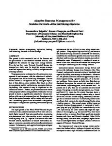
In this work, we encompass the concepts of hierarchical and MA-based distributed management. The introduced MDM entities resemble the SNMPv2 proxy agents with their mobility feature used to increase management flexibility. MDMs are assigned to a domain given that certain criteria (determined by the administrator) are satisfied. For instance, when the manager station ascertains that the number of managed devices in a remote segment has increased beyond a pre-specified limit, it will choose to deploy an MDM to that segment (Figure 1a). Upon arriving to its assigned remote domain, the MDM will take over the management of local devices from the central manager. As a result, the traffic related to the management of that domain becomes localised, as the MDM is able to dispatch and receive MAs to collect NM data from the local hosts, or even execute centralised management operations on them (Figure 1b). Management functionality may be downloaded at runtime, i.e. the central manager may send to distributed MDMs new MA configurations corresponding to introduced management tasks. In addition, this architecture is adaptive to changing networking conditions since the location and the roles of the entities involved in the management procedure may be dynamically modified. Namely, an MDM entity can be
deployed to / removed from a network segment in response to a change in network topology or traffic distribution. Manager
Manager
1 MIB
MIB
MDM MAS
MAS
MAS
Agent
Agent
Agent
MIB
MIB
2
MDM MAS
MAS
Agent
Agent
MIB
MIB
(a)
MAS
MAS
MAS
Agent
Agent
Agent
MIB
MIB
MAS
MAS
Agent
Agent
MIB
MIB
(b)
Figure 1. The proposed architecture
Certainly, the fact that MDMs rely on other MAs to sequentially visit managed devices and collect data brings about performance issues, especially when these MAs need to be frequently transferred. However, in a variety of monitoring applications, MAs may beneficially use the knowledge (data) already obtained from previously visited hosts to apply a second level of data filtering at each hop, thereby minimising the use of network resources [9]. In performance management applications, only aggregated values and statistics are sent to the manager at regular intervals, diminishing the amount of data transferred through the WAN link. The duration of these intervals is taskdependent and determined by the administrator. MDMs also improve the system’s fault tolerance, as they continue to perform their task without the manager’s intervention, even if the interconnecting link fails. It is noted that the management domain assigned to an MDM entity can be confined to a single network segment or expand to a larger set of hosts. In the latter case, when the population of the remotely managed devices increases beyond a certain limit, the MDM will be instructed to clone itself, with its duplicate object transparently sent to a nearby segment and taking over its management. A key issue in the framework's design has been to equally distribute the total workload among the various processors of the underlying subsystems. Hence, MDMs are originally deployed to the least loaded host to minimise the usage of local resources, while they can transparently migrate to another device as soon as their hosting system becomes overloaded. In conclusion, the proposed hierarchical NM model adds flexibility and scalability to the management system. That is, the location where MDMs run is not fixed, neither is the set of hosts under their control. MDMs can be transparently sent to a domain when the associated cost savings are considerable or removed when their existence is no longer necessary. It is noted that the described architecture has been developed on the top of the framework described in [7]. Among other features, that framework includes a security-
enhanced MA execution environment and a tool that automatically generates the code of task-oriented MAs. Similar work has been reported in [8] that comprises an interesting study of an MA-based management architecture adopting a hierarchical, multi-level approach. However, there is no implementation supplementing this work, while the authors have not considered providing mobility features to their “Middle Managers”, so as to dynamically change their location, resulting in a static management hierarchy. In addition, the criteria according to which the managed network is segmented in domains and the way that these domains are assigned to Middle Managers are not clarified. III. ARCHITECTURE DESIGN AND IMPLEMENTATION In order to provide a functional verification of the proposed hierarchical framework and assess its impact upon realistic network environments, we complemented our design ideas with a prototype. Java was the chosen implementation platform due to its inherent portability, rich class hierarchy and dynamic class loading capability. The prototype has been tested on a LAN comprising a number of WinNT and Solaris machines. A. Topology Map of Active Devices An important element of our framework is the topology map, a graphical component of the manager application, used to view the devices with currently active MAS servers and the underlying topology of the managed network (Figure 2a). In terms of implementation, the topology map is internally represented by a tree structure (termed the “topology tree”), where each of the tree nodes corresponds to a specific subnetwork. The node representing the manager’s location is the root of the topology tree (see Figure 2b).
Hosts
Hosts
Routers
Routers
Sub-network C
Hosts
Sub-network D
Hosts
(a)
Routers
Routers
(b)
Figure 2. (a) Topology map’s snapshot, (b) The topology tree structure
a flag indicating the presence of an active MDM on this subnetwork; the number nl of local active hosts on this subnetwork; the number ns of active hosts on the subnetwork’s “subtree” (the term subtree here denotes the set of subnetworks located in hierarchically lower levels in the topology tree, including the present subnetwork itself), hence n s ≥ nl ; a pointer to the upper level tree node; pointers to the next level nodes; a list of graphical components, each corresponding to a specific host, that will be made visible upon discovering an active MAS entity on that host. For instance, the number of active hosts in the subtree of Subnetwork A (in Figure 2b) will be:
n s ,subA = nl ,subA + nl ,subB + nl ,subC + nl ,subD
(1)
All the information related to the managed network topology described above, is given to the manager application upon its initialisation, through parsing a text file (“network configuration” file). The configuration file does not include, of course, the activity status information, which is automatically discovered by the manager (the manager application ‘listens’ for related broadcast messages of the activated MASs). For each file entry, a new subnetwork node is created and inserted into the topology tree. In particular, its ‘parent’ (upper-level) subnetwork is located and then the next-level pointer of the parent node as well as the upperlevel pointer of the inserted node are updated. As shown below, the topology tree plays a crucial role when the manager application needs to make a decision on which subnets require the deployment of an MDM entity. B. MDMs Deployment Policies
Manager Platform
Sub-network A
Sub-network B
Each of the tree nodes consists of the following attributes: the subnetwork’s name; the names of hosts and routers physically connected to this subnetwork;
A key characteristic of this work is the dynamic adaptation of our architecture to changes in the managed network. The structure of the proposed model is not rigidly designed, as MDMs may be dynamically deployed to specific network domains, given that certain requirements are met. Namely, the administrator may explicitly set the policies that define the hierarchical NM system operation, i.e. specify the criteria that should be satisfied for deploying an MDM to a network segment. In general, the administrator may choose one of the following two policies to determine the MDMs deployment strategy: Policy 1: the population of remotely active managed devices. Policy 2: the overall cost involved with the management of a remote set of devices. In the former case (Policy 1), the administrator specifies the number of remote managed NEs that will justify the deployment of an MDM to a particular network segment. This number may either denote nl or ns. If, for instance, the
specified number N denotes the population of the examined subnetwork’s local devices nl, an MDM will be deployed to every network segment S with nl ,S ≥ N , otherwise to every segment with n s ,S ≥ N . In the latter case (Policy 2), the management cost may either be: (a) proportional to the inverse of link bandwidth, or (b) manually specified. By choosing appropriate constants, the administrator may either enforce or impede the deployment of MDMs. C. Implementing MDMs Deployment Upon discovering an active MAS module, the corresponding host is located through scanning the topology tree and finding the subnetwork where the host belongs, whilst the host icon is instantly made visible on the topology map. Then, the number nl of active hosts on that subnetwork is increased by one and subsequently, through following the pointer to the upper-level nodes, all the topology tree nodes up to the root are traversed and their number ns of subtree nodes is also updated. A similar procedure is followed when an MAS server is being shut down. The discovery or termination of an MAS server triggers an event at the manager host. The topology tree is then scanned and an MDM is sent to each subnetwork that meets certain requirements. In case that ‘Policy 1’ is employed, referring to the policies listed in the preceding section, the chosen subnetworks will include those with nl or ns (depending on whether the MDMs deployment is a function of the active devices running locally or in the whole subtree) greater than the specified constant N. If ‘Policy 2’ is employed, the cost corresponding to the management of each subnetwork is evaluated and the list of subnetworks created accordingly. Ultimately, an MDM will be deployed to each of the subnetworks included in the list. The MDMs deployment algorithm is illustrated in the Figure 3 flow diagram (we assume that Policy 1 is used). S tart W ait fo r an M A S serv er activ atio n
F in d th e to p o lo g y tree n o d e S ‘in clu d in g ’ th e d isco v ered h o st
V isit n ex t su b n et S
n l,S > N ?
U p d ate n l,S an d n s,S No
D isco v ered a n ew M A S ? Y es
M ak e th e h o st ico n v isib le o n th e to p o lo g y m ap
Yes
along with the MDM. PTs are originally started and controlled by the manager application with each of them corresponding to a single monitoring task. Unfortunately, PTs cannot be transparently transferred along with the MDM retaining their execution state, due to a Java constraint (Java does not support threads serialisation/deserialisation). Hence, PT attributes are saved in configuration files, which are ‘attached’ to the MDMs when sent to a remote domain. Upon its arrival at the remote subnet, the MDM instantiates the PTs using their configurations. The PTs will thereafter start performing their tasks without any further disruption of the management process: they launch the required number of MAs (supplied with their corresponding itinerary) and then ‘sleep’ for one polling interval. When this period elapses the same process is repeated. Meanwhile, an MDM’s listener daemon receives the MAs that return carrying their collected data. D. Optimising Host Resources Utilisation Although MDMs have been designed to be as lightweight as possible, they cannot avoid consuming memory and processing resources on the NE where they execute. The framework should therefore be sufficiently flexible to allow MDMs to autonomously move to another host, when their current hosting device is overloaded, in order to provide a more balanced distribution of the overall processing load.
Host B
Resources inspector
CPU: 78%
CPU: 49%
Mem: 65%
Mem: 18%
Host A
Host C
Host E
Host B
Host A
D ep lo y an M D M to S
Y es
P rep are to trav erse th e to p o lo g y tree
Figure 3. MDMs deployment algorithm diagram
Certainly, the set of management tasks already performed by the manager on these subnetworks will need to be conveyed to the MDM deployed therein. This is achieved through sending the Polling Threads (PT) configurations
Host D
(b)
Host E
Host B
Host A
Host E
Host D Host C
Host D
CPU: 28%
T ree trav ersed ?
E nd
Host E
Inform the manager station
No
No
Host A
Host C
Host D
(a)
Host C
T rav erse th e b ran ch in clu d in g n o d e S u p to th e ro o t u p d atin g n s,S ’ fo r each n o d e S ’
Host B
Mem: 14%
(c)
(d)
Figure 4. Migration of the MDM to the least loaded host within its assigned domain
This is accomplished through the regular inspection of the domain’s NEs, in terms of their memory and CPU utilisation: an MA object, termed Resources Inspector (RI), is periodically dispatched and visits all the local devices obtaining these figures before delivering the results to the MDM. If the hosting processor is seriously overloaded, compared to the neighbouring devices, the MDM will
transparently move to the least loaded node. In the example depicted in Figure 4, an RI sequentially visits all the managed devices in the MDM’s local domain. At each host, the RI obtains the average CPU & memory load values during the last interval, keeping track of the least loaded device (in this example that will be Host D). Finally, the RI reports its results to the MDM, which in turn transparently migrates from Host A to Host D after informing the manager application about its decision. E. Obtaining Host Load Profile In order to obtain a view of devices load we have built a tool, developed in C, able to accurately measure the CPU and memory load profile. On the Windows platforms, the lowlevel functions included in the Win32 API [10] are used, whereas standard UNIX commands (e.g. the ps command) are executed under Solaris. The integration of this tool with the MAS application, developed in Java, is achieved through the Java Native Interface (JNI) [11]. The JNI allows Java code that runs within a Java Virtual Machine to operate with applications and libraries written in other languages, such as C or C++. JNI is used to write native methods to handle those situations when an application cannot be written entirely in Java. The Java front-end (methods) accessed by the incoming RIs provides them a uniform handle onto the local resources, whilst hiding the underlying architecture, i.e. the native methods implementation. ‘Snapshots’ of hosts load profile are taken in regular intervals. The duration of these intervals should be carefully set: it should be long enough to avoid sensitivity on sporadic load peaks and, at the same time, short enough so as not to omit potentially prolonged increments of the processing load. F. Manager-MDMs Communication One of our framework key advantages is that it greatly reduces the amount of information exchanged between the manager platform and the managed devices. This is due to the introduction of the intermediate management level (MDMs). However, that does not obviate the necessity for bidirectional communication between MDMs and the manager host. In particular, MDMs often need to send the manager the statistics obtained through filtering raw data collected from the local devices, inform the manager when migrating to another host, etc. In the opposite direction, the manager may request an MDM to terminate its execution, move to another domain, create a clone and send it to a nearby segment, update a PT configuration, modify the statistics delivery frequency, undertake the management responsibility of a host that has just started execution on the MDM’s local segment, download in runtime an additional management service, etc. Java Remote Method Invocation (RMI) has been chosen for implementing the communication bus between the
distributed MDMs and the manager host, due to its inherent simplicity and the rapid prototype development that it offers. IV. CONCLUSIONS This paper proposed the use of MA technology for dynamic hierarchical management. In this context, we introduced the MDM, a novel management entity, which can be assigned to a given network segment at runtime to localise the associated management traffic. MDMs are enhanced with mobility capabilities allows the management system to instantly adapt to potential changes of the managed network topology or traffic distribution and optimise the use of local resources. In addition, the use of MAs with filtering capabilities reduces the cost associated with the actual management data collection procedure. The design of our framework is supplemented by a prototype implemented in Java and tested under realistic network conditions. ACKNOWLEDGEMENTS This work has been funded by Fujitsu Telecommunications Europe Ltd. We are also grateful to Paolo Bellavista, Prof. Antonio Corradi and Dr. Christina Politi for their insightful ideas during the framework's development phase. REFERENCES [1]
Martin-Flatin J-P., Znaty S., "Two Taxonomies of Distributed Network and Systems Management Paradigms", Chapter 3, "Emerging Trends and Challenges in Network Management", Plenum Press, New York, NY, USA, 2000. [2] Perkins D.T., “SNMP Versions”, Simple Times, 5(1):13-14, 1997, http://www.simple-times.org/. [3] Goldszmidt G., “Distributed Management by Delegation”, PhD thesis, Columbia University, New York, NY, USA, Dec. 1995. [4] Pham V., Karmouch A., “Mobile Software Agents: An Overview”, IEEE Communications, Vol. 36, No 7, pp. 26-37, 1998. [5] Puliafito A. Tomarchio O., “Using Mobile Agents to implement flexible Network Management strategies”, Computer Communications, 23(8), pp. 708-719, April 2000. [6] Rubinstein, M., Duarte O. C., Pujolle G., "Reducing the Response Time in Network Management by Using Multiple Mobile Agents", Proc. of the 4th Int. Conf. on Autonomous Agents (Agents'2000), June 2000. [7] Gavalas D., Greenwood D., Ghanbari M., O’Mahony M., “An Infrastructure for Distributed and Dynamic Network Management based on Mobile Agent Technology”, Proc. of the IEEE Int. Conf. on Communications (ICC’99), pp. 1362-1366, June 1999. [8] Liotta A., Knight G., Pavlou G., Modelling Network and System Monitoring Over the Internet with Mobile Agents”, Proc. of the IEEE/IFIP Network Operations and Management Symposium (NOMS'98), pp. 303-312, Feb. 1998. [9] Gavalas D., Greenwood D., Ghanbari M., O’Mahony M., “Enabling Mobile Agent Technology for Intelligent Bulk Management Data Filtering”, Proc. of the 2000 IEEE/IFIP Network Operations and Management Symposium (NOMS’2000), pp.623-636, April 2000. [10] Platfptm SDK: Win32 API, http://msdn.microsoft.com/library/ psdk/portals/win32start_1n6t.htm. [11] Java Native Interface (JNI), http://java.sun.com/docs/books/ tutorial/native1.1/index.html.