of a machine vision system with such a device would typically be considered ... programmable logic device to generate the subsampled. Fig 1. Block diagram of ...
Implementing Active Vision in Embedded Systems Gordon Wyeth Department of Electrical and Computer Engineering University of Queensland Brisbane, Australia
Abstract Machine vision is a powerful tool for process automation and control. However, the memory requirements and interface overheads of video buffers found in typical video grabbers are not easy to interface to low cost embedded systems. This paper describes an active vision interface that enables a low end microcontroller to use a standard video camera as an input for process control. The active vision interface consists of a frame grabber with a small (4 kb) memory mapped buffer that can be zoomed out to sample the whole image at low resolution, or zoomed in and panned around the image at high resolution. This scheme takes advantage of the fact that most real time vision systems operate on low resolution images or small parts of a high resolution system in order to reduce the number of operations performed on each frame. The system integrates tightly with the embedded microcontroller by providing current video in the microcontroller’s memory space. This minimises the overheads in interfacing and maximises the bandwidth to the vision processing algorithm. The interface has been designed to minimise latency, and to provide contention-free access to live video.
1 Design Aims The aim of this design was to produce a low cost machine vision system that can operate with real time embedded systems. Low cost embedded systems often use low-end microcontrollers, typically 8-bit devices with a built-in peripheral set useful for process control (the ubiquitous Motorola MC68HC11 for example). The use of a machine vision system with such a device would typically be considered impractical, forcing the designer to a higher cost DSP processor, or even a multiprocessor
design, or perhaps to abandon the use of machine vision in the application. The low cost of the system described here, and its compatibility with low end microcontrollers makes the use of machine vision practicable in situations where a machine vision approach may previously have been ruled out as too costly. The difficulty lies in the number of pixels that need to be stored and processed. Routines used for real time machine vision usually operate on a small number of pixels - processing arrays of 512 x 512 (262144) pixels in milliseconds is a difficult task for even high performance processors. A useful array size is 64 x 64 (4096) pixels, which is manageable on slower, low cost processing systems. However, low resolution images will compromise image clarity, particularly if a wide field of view is required to ensure that the object of interest is in the camera viewing region. An active vision system with the ability to select a region for sampling from anywhere within the camera image increases the applicability of a low resolution system. Such a system could select 64 x 64 pixels sampled across the entire camera region (zoom out), or sample at camera’s maximum rate in a small region (zoom in). The region to be sampled could be chosen from anywhere in the image (panning). This programmable pan and zoom feature replaces mechanical pan and zoom systems where low resolution images are used. For example, consider a conveyor belt with randomly placed items to be quality checked. A low resolution grab across the entire camera’s visual range can be used to locate an item for checking. During the vertical retrace period of the camera, the active vision system can be reprogrammed to capture a high resolution grab in the vicinity of a located item. This high resolution image can then be used for the quality check (or orientation calculation or part recognition or for determining some other process variable). One possible approach to the design of such a system would be to grab the complete array of pixels (512 x 512) and subsample in software. There are several disadvantages to such an approach. Firstly, the image
requires 256 kbytes of storage for an 8-bit image. Many low cost microprocessors have only limited memory space, making the interface to the image difficult. Secondly, the process of subsampling the image wastes valuable processor time. The subsampling process decreases the throughput of the machine vision system, and increases the latency between sensor input and actuator output -- a critical factor in the stability of the process control. Finally, the cost of the storage space for the large array of pixels is significantly higher, particularly for a memory system that can provide the fast, continuous access required for real time machine vision. The approach discussed in this paper describes a modification to the timing hardware of a typical frame grabber design. The modification makes the timing hardware programmable, which creates a hardware subsampling function which can provide the pan and zoom required of an active vision system. Moreover, the design ensures maximum throughput and minimum latency reducing the load for the vision processor. Most importantly the design operates in a small memory space
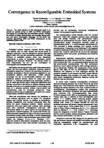
Fig 1. Block diagram of the active vision system
(4 kbytes), reducing the cost of the memory subsystem and making the design compatible with low cost embedded systems.
2 Design Details An overview of the design is shown in Figure 1. The system is not significantly different from any other frame grabbing system when viewed from this perspective. The only notable differences are microcontroller bus connections to the timing hardware. These connections facilitate the programming of the timing for the pan and zoom functions. The following sections look at the design in overview and then explain some of the specific features of the timing system and the software interface.
2.1 Design Outline The active vision system uses a video sync stripper (Bt261) and flash ADC (Bt208) from Brooktree [1] and a programmable logic device to generate the subsampled
image. To avoid conflict between the image being written by the video sampler and the image being read by the microcontroller, the video RAM buffer is stored in two banks, which are switched as alternate fields are read. The video RAM is dual ported, with one port being connected directly to the CPU bus. The RAM buffer is stored in the processor's memory space, enabling the CPU to have direct access to the image. This means that the processor has continuous access to video that is only 20 ms (one field) old. The sub-sampling method is implemented by varying the timing of the samples. To capture the whole field of view, the 64 x 64 pixels can be captured at one quarter of the video rate. That is, the vertical sampler only looks at every fourth line, and the horizontal sampler samples those lines slowly, in such a manner that it only takes 64 samples across the whole width of the line. However, when the active vision system requires more detail of a given part of the field of view, the vertical sampler can be programmed by the CPU to every second or third line, or every line, and to start sampling at any given line of the field. The horizontal sampler can be programmed to start at any position on the line, and to sample at any given rate in multiples of 100 ns. In this manner, the camera can effectively pan and zoom without any mechanical movement.
2.2 Timing Generation The first step in the timing process is the extraction of the sync signals from the video signal. This process is performed by the Bt261 sync stripper. This device also contributes to the next part of the timing problem. As can be seen from Figure 2, the Bt261 contains features for the generation of horizontal timing. In short, the Bt261 produces logic level horizontal and vertical sync signals, a clock signal for a programmable horizontal sampling rate, and an enable signal for a programmable horizontal sampling window. The vertical timing and address generation was performed by a programmable logic device. In a typical image grabber, the address generation is performed by a counter clocked from the sampling clock. In principle, the address generation implemented in the active vision system is much the same with the addition of some registers that modify the behaviour of the counters. As can be seen from Figure 3, the horizontal address (the least significant 6 bits) are generated by counting the clock pulses. Instead of overflowing into the vertical address counter as one might expect with a traditinal image grabber, the horizontal counter overflows into a skipped line counter. The value of the skipped line counter is compared with the value in the skip register, which holds the number of lines to be skipped. The vertical address counter is only enabled when the skip
Fig 2. Block diagram of the Bt261 Line Lock Controller (reproduced from [1]).
Clear From Bt261
Horizontal Address Counter
Video Address (Bits 0-5)
Overflow Counter
Vertical Address Counter
Overflow Counter
= From Micro
Skip Register
Video Address (Bits 6-11)
=
Chip Select Logic
Start Register
Video RAM Chip Selects
Fig 3. Block diagram of the video address generation and the vertical timing logic. value is reached. The vertical address counter also overflows into another counter. This is necessary for detecting the starting line, which may be greater than the number of lines in the sample window. The lower bits of the vertical address and the overflow counter bits are concatenated and compared with the starting line number (stored in the start register). The chip select lines for the dual port RAM are not enables until this line is reached. Naturally, the vertical address counter is reset at this point for correct vertical address generation. For every second frame, the chip select lines toggle so that alternate banks of video memory are used.
2.3 Software Library A C software library was developed for the frame grabber. The software interface has two functions vid_open() and vid_set(xpan, ypan, zoom) which initialise the card, and set the pan and zoom of the card respectively. The initialisation of the card involves programming some of the registers in the Bt261 not involved with the variable sampling rate, as well as setting up default values for both horizontal and vertical sampling. A call to vid_set programs the start values for both the horizontal and vertical counters (xpan and ypan), as well as setting appropriate sampling values
(zoom). The horizontal and vertical sampling values are linked to ensure that a correct aspect ratio is maintained. The other part of the interface is a pointer (VRAM), that allows the video RAM to be accessed directly as an array of 4096 bytes. For example, the first pixel on the third line of video can be accessed with a statement like: value = VRAM[128]; Video is accessed by direct memory reads, involving no function calls. This ensures the least possible overhead to current video.
3 Performance Review The active vision system has been implemented and is in use in a mobile robot controlled by a low cost microcontroller (Motorola 68HC16) [4]. The robot is able to perform recognition of tennis balls at frame rate (25 Hz) with ten fixed point “multiply-and-accumulate” operations per pixel. While performing the recognition task, the processor is still able to maintain other robot systems functions such as motor control, I/O management and task switching. The robot can also be configured to capture images and transmit them through a serial communications port to a PC. Some sample images are shown in Figure 4. As can be seen from these images, the grabber can successfully grab a wide field of view and zoom in on a region of interest (in this case a
Fig 4. Sample images from the active vision system.
tennis ball). The throughput and low latency of the frame grabber enables the robot to react rapidly to changes in the environment, and even to play chase with a moving tennis ball. The pan and zoom functions allow the robot to recognise tennis balls that are some distance away, by investigating regions of interest detected from a broader view of the environment.
3.1 Improvements to the System Use of the frame grabber has revealed the need for some minor modifications to achieve maximum utilisation of the frame grabber’s resources. These additions relate to synchronising the microcontroller with the incoming video. Firstly, a “frame ready” output would be useful for establishing the arrival of new video data for when the processor is able to process faster than the field rate. This output is readily derived from the current chip select logic. Conversely, a “freeze frame” input to the grabber would be useful for when the processor is slower than the field rate. When the processor is running slower than the field rate, the banks will switch while an image is being analysed. For some algorithms, or for fast moving images, this may cause corruption in the analysis of the image. A solution to this problem is to copy the video memory to main memory, but this is an unnecessary overhead for the system. The “freeze frame” input would disable the bank switching, causing the new video data to be written to the unseen bank while a coherent copy of the image being processed remains in the accessible bank. Again, this change can be made with slight modification to the chip select logic.
The video RAM appears much the same as any other static RAM from a microprocessor interface point of view. The general nature of the interface would allow interface to other low cost, high performance microcontrollers, such as Hitachi’s SuperH series, to achieve 50 fixed point “multiply-and-accumulate” operations per pixel at field rate (50Hz) [3]. The system can, in fact, be used with any number of processors, although its design is oriented towards the low end range of microprocessor range. To achieve a further reduction in total overheads, the system could be readily adapted to drive a CCD element rather than reading a video signal. The major change to the structure of the grabber would be the replacement of the Bt261 with a device to generate the necessary waveforms to clock the CCD element. The timing and memory setups could remain much the same. This device may best be implemented using a small microcontroller such as a PIC device from Microchip [2]. In fact, such a microcontroller may be able to perform the address generation and timing as well, eliminating the need for the programmable logic device.
4 Conclusions This paper outlines a design for a frame grabber suitable for use with the low end microcontrollers typically found in embedded systems. It shows that a small addition to the hardware of the frame grabber can produce an active vision system, capable of pan and zoom functions without any moving parts. The design has been successfully implemented and is in use in a practical application.
References [1]
- (1991) Brooktree Graphics and Imaging Product Databook, Brooktree Corporation, 1991. [2] - (1993) Embedded Control Handbook, Microchip Technologies, November 1993.
[3]
- (1995) SH Series SuperH RISC Engine Overview, Hitachi, October 1995. [4] Wyeth, G. F. (1997) CORGI: A Robot to Play Fetch, To appear in Australian Journal of Intelligent Information Processing Systems, Special Issue on Robotics, ed. A. Zelinsky.