Implementing Industrial Multi-Agent Systems using JACKTM Rick Evertsz1 , Martyn Fletcher1 , Richard Jones1 , Jacquie Jarvis1 , James Brusey2 , and Sandy Dance3 1
Agent Oriented Software Pty. Ltd. (AOS), 156 Pelham Street, Carlton, Melbourne, Victoria 3053, Australia. {rick.evertsz, martyn.fletcher, richard.jones, jacquie.jarvis}@agent-software.com 2 Institute for Manufacturing, University of Cambridge, Mill Lane, Cambridge CB2 1RX, United Kingdom.
[email protected] 3 Bureau of Meteorology Research Centre, 150 Lonsdale Street, Melbourne, Victoria 3000, Australia.
[email protected]
Abstract. JACKTM is an implementation of the Belief/Desire/Intention model of rational agency with extensions to support the design and execution of agent systems where team structures, real-time control, repeatability and linkage with legacy code are critical. This chapter presents the JACK TM multi-agent systems platform. The chapter begins with a discussion of agent programming concepts as they relate to JACKTM , and then presents experiences from the development of two industrial applications that made use of JACKTM (a meteorological alerting environment and a responsive manufacturing set-up).
1 Introduction Over the past decade, there has been an increased industry interest in the application of multi-agent systems. With the advent of distributed software applications, traditional approaches to programming the interaction between sub-systems has proven to be time consuming and error prone. Typically, distributed systems are embedded in, and must interact with, a changing environment. The interaction with the environment is particularly problematic where there are many external entities that must be controlled, serviced or modelled. In the past, implementing such systems has entailed explicit programming of the interaction with each external entity. If this is more than a simple client/server interaction, then the application can become hard to manage, that is, difficult to implement, maintain or change. Furthermore, the application may not have the required flexibility or responsiveness to its environment. Agent-based approaches have proven to be well suited where complex interaction with an ever-changing environment is required. Arguably, the most significant attribute of agent-based systems is that each agent is an autonomous computational entity. Autonomy, coupled with an ability to perceive the environment, act upon it and communicate with other agents, provides system builders with a very powerful form of encapsu-
lation. A given agent can be defined in terms of its goals, knowledge and social capability, and then left to perform its function autonomously within the environment it was designed to function in. This is a very effective way of building distributed systems— each agent in the system is responsible for pursuing its own goals, reacting to events and communicating with other agents in the system. There is no need to explicitly program the interactions of the whole system; rather, the interactions emerge as a by-product of the individual goals and capabilities of the constituent agents. In the next section, we will further expand our discussion of the motivation for adopting agent-oriented design and programming in industry. This chapter provides an overview of the Belief/Desire/Intention (BDI) paradigm and the JACKTM intelligent agents platform, and presents in some depth two industrial applications of JACKTM . The BDI paradigm underlies JACKTM and has been extensively studied in academia [1,2,3] and has been applied to a number of problems in industry [4,5,6,7].
2 Agent Programming Concepts In the software industry, the term software agent has been used to denote a wide range of programming approaches. Nevertheless, within the computer science research community, the consensus on the core attributes of software agents seems to be as follows (and we shall adopt this view of agency throughout this chapter): Autonomous An agent operates without continuous external supervision. Proactive/Reactive An agent exhibits both goal-directed and reactive behaviours. Situated An agent perceives a relevant subset of its environment, and reacts to changes in a timely, quasi real-time fashion. Social An agent can interact with other agents to achieve joint goals. In this section on agent programming concepts we discuss why these core attributes of agents are critical for developing industrial-strength autonomous and multi-agent systems. We highlight the motivation for building industrial applications using the agent paradigm and describe how the Belief/Desire/Intention (BDI) model of rational agency provides a solid foundation for engineering such commercial systems. 2.1 The Motivation for Agent-Oriented Programming in Industry Increasingly, software applications need to be more reactive and distributed in nature. Examples include the telecommunications industry where dynamic interactions between mobile entities can require complex coordination protocols. Techniques developed to implement single-threaded control in relatively static environments do not scale well to dynamic, distributed domains that require multiple threads of interaction. The pressing practical need for more event-driven, decentralised and multi-threaded software has led to an interest in the application of agent-oriented techniques within industry.
To illustrate this point, consider an air traffic management application where the goal is to optimise the flow of aircraft landing at a major airport. At any given moment, there will be a collection of aircraft approaching from various directions, altitudes, speeds and distances. In an ideal world, they would all arrive at the runway perfectly spaced to avoid conflicts, and would optimise the utilisation of the precious runway resource. Naturally, in the real world this does not happen without continuous and expert human intervention by an air traffic flow manager. The flow manager must monitor the progress of the aircraft, estimate when they will arrive at the airport, generate a landing sequence that ensures that they do not compete for the same piece of runway time, and then issue speed instructions to ensure that the aircraft arrive at the airport as sequenced. This is a very dynamic and complex domain; for example, – an aircraft can drift from its assigned landing time due to factors such as unanticipated headwinds, or – a pilot, with extensive local knowledge of the airport, may cut corners on the flight path in an attempt to “jump the queue”. Thus, the flow manager must constantly monitor the progress of the (upwards of fifty) aircraft and adjust their speeds and trajectories to bring them back into line with the sequence. This is such a complex task, that human flow managers use “rules of thumb” to short-circuit the computation required to produce a truly optimal schedule. As a result, the schedule is sub-optimal in terms of ideal utilisation of the runway resource, but is workable and avoids runway collisions among aircraft. Implementing the flow management function using a conventional software approach is non-trivial. It requires a number of functions that must be applied in a constantly changing environment. These functions include applying the performance profile for each type of aircraft, estimating the effects of wind, optimising the sequence of arriving aircraft, generating flow instructions that satisfy the sequence, and predicting the behaviour of pilots based on their familiarity with the airspace. These functions need to be run periodically, but must also be triggered in response to unanticipated events (e.g. radar position data showing that an aircraft has diverged from its expected flight plan). Because of the inherent complexity of interactions between the entities and the environment, traditional software approaches lead to a monolithic code-base that is errorprone and difficult to alter without breaking the carefully coded handling of the dynamic aspects of the problem. These approaches involve constructs such as a process scheduler that loops through each of the aircraft, checking their progress and updating the landing schedule in a rigid and therefore potentially maladaptive fashion. If the environment changes during the execution of the loop, what is the process scheduler to do? Should it interrupt the loop and start again with the first aircraft, or should it continue to the end in the hope that its computations will still be applicable? These considerations make it very difficult to build software that can survive in a highly dynamic environment, and provide strong motivation for the adoption of agent-oriented programming within industries where unpredictable events, resource failure, and the unplanned introduction of heterogeneous entities are commonplace. Agent-oriented programming is well suited to such dynamic problems. For instance, an Aircraft Agent can autonomously monitor the state of each physical aircraft. The
agent is equipped with the appropriate performance profile for the aircraft type, and can take input from a Wind Agent that models the winds aloft. The Sequencer Agent is responsible for computing the optimal landing sequence, requesting an Estimated Time of Arrival from each Aircraft Agent, and then assigning a new landing time that respects the sequence. The Aircraft Agent then uses its performance profile and the Wind Agent’s input to compute the speed alteration required to arrive at the airport as sequenced. The aircraft flow management problem is greatly simplified by adopting this agentbased approach, because each real world entity is mirrored by an autonomous entity within the software itself. Indeed an agent-based flow management system was successfully operationally tested at Sydney Airport (Australia) in 1995, and was based on an architecture very similar to the one just described [7]. 2.2 The Belief/Desire/Intention (BDI) Paradigm Due to space limitations, this overview of the BDI paradigm will not attempt to provide a comprehensive review. Rather, our goal is to lay the foundation for subsequent sections by outlining BDI as it pertains to the JACKTM intelligent agent platform. For a more comprehensive review, please refer to [3]. JACKTM is based on the Belief/Desire/Intention (BDI) model; a paradigm that explicates rational decision making about actions. Based on work by Bratman [8] on situated rational agents, and developed further at SRI International (Menlo Park, California), this approach has been applied to a wide range of problems, from its early focus on fault diagnosis for Space Shuttle missions [9], through simulation of intelligent entities such as combat pilots [10], to teamed unmanned air vehicle control [11]. The BDI paradigm was developed in response to a perceived problem with existing Artificial Intelligence (AI) approaches to the planning problem. The planning problem can be stated informally as: “Given a goal, generate a sequence of actions that will achieve that goal”. Research on this problem was successful in developing generalpurpose techniques, mostly based on some variant of means-ends reasoning (e.g. the work of Fikes and Nilsson [12]). However, these approaches only addressed the offline planning problem—how to achieve the goal given infinite time and resources. They did not address the temporal pressures that apply when trying to achieve the goal within the context of a fluctuating environment that presents a multitude of interacting, conflicting and changing opportunities. Yet, this is the rule rather than the exception in modern industrial situations; it is rare that an agent situated in the real world can take as long as it likes to solve a problem. The world is constantly changing, and with it comes demands on the agent requiring that it reconsider its priorities. When you sat down to read this chapter, your goal may have been to learn about the practical applications of agent programming, and you might have set aside a couple of hours for this endeavour. However, if you unexpectedly received a phone call from a friend asking to be picked up from the airport in thirty minutes time, you might decide to read this article less thoroughly, perhaps returning to it tomorrow. If you were then informed that a burst pipe was flooding your home, you would very likely drop everything and scramble to deal with the unexpected crisis. Though inconvenient, we must deal with an environment that is in constant flux, and
this reality applies equally well to software systems that are situated in the real world (such as the air traffic management system referred to earlier). This then was the motivation for the development of the BDI paradigm. Agents are typically situated in a dynamic environment and must constantly review their goals and activities, and should also be aware of the resource-bounded nature of their reasoning. Bratman et al. [13] presents the case for this resource-bounded view of rational agency. Georgeff and Lansky [14] developed an early implementation of the BDI approach to agents—the Procedural Reasoning System (PRS). PRS was the forebear of a lineage of commercial BDI implementations that includes dMARS [1] and has culminated in JACKTM [15]. PRS was developed at SRI International and has been applied to fault diagnosis of the Space Shuttle, telecommunications network management and air traffic management. To better address the requirements of commercial software environments, in the early 1990s, PRS was re-implemented in C (C-PRS [16]) and also re-designed and implemented in C++ as (dMARS [1]). Though re-designed from the ground up, this second generation BDI implementation, dMARS, was largely backwards compatible with PRS and enabled the operational testing of the PRS-based OASIS air traffic management system at Sydney airport [7]. dMARS was also used to implement SWARMM, an air combat modelling system, with agents taking on the role of synthetic pilots for the purposes of evaluating air combat tactics [10]. After eight years of use by the Royal Australian Air Force (as of 2003), a successor to SWARMM is being implemented in JACKTM . JACKTM is implemented in JavaTM and includes significant extensions to the BDI paradigm (in particular, its support for team coordinated activity). JACKTM was specifically designed for commercial application and will be described fully in section 3, but first we will describe the key features of BDI agent systems.
2.3 The PRS Family and the BDI Paradigm Although the members of the PRS family of BDI agent systems differ from one another in terms of implementation detail and range of ancillary features, they are based on a similar interpretation of BDI. This is due in part to the fact that there is considerable overlap between the members of the teams that designed PRS, C-PRS, dMARS and JACKTM . Although it is not the purpose of this chapter to provide a comparative review of these systems, it is beneficial to outline the common features of these BDI implementations. This provides an insight into the aspects of the BDI paradigm that have a proven track record of practical application within industry. As the latest incarnation of commercial BDI implementations that stem directly from PRS, JACKTM has dispensed with some of the more esoteric PRS attributes, concentrating instead on providing a compact and efficient set of core features. In addition to these core features, JACKTM has extended the BDI paradigm to deal with inter-agent coordination, and includes new constructs and tools that support the software engineering process. These extensions will be covered in section 3. The key programming constructs of a BDI design are as follows:
Events Deliberation is triggered by events. Events can be received from the environment but are also internally generated. Such internally generated events function as goals. This is a key aspect of PRS-based BDI. Plans The procedural knowledge of the agent (what Bratman et al. [13] refer to as “plans-as-recipes”). Plans define how the agent should behave in response to events. Non-deterministic choice allows the agent to try alternative plans to achieve the same goal, and to fill out the lower-level details of the plan (what Bratman et al. [13] call “partial plans”). Beliefs An agent’s knowledge of its environment, but not including plans (plans are procedural knowledge about what action sequences can satisfy a given goal). Plans are represented separately from declarative beliefs. Agents Autonomous computational entities with their own external identity and private internal state. Intentions The currently active plan instantiations, i.e. the plan instances that the agent is committed to. Plans are abstract entities that describe potential patterns of behaviour. A plan becomes an intention when the agent instantiates it with symbolic references to concrete entities in the environment, and commits to its execution. Meta-level reasoning If more than one plan is applicable for a particular event, infrastructure is provided that enables meta-plans to be invoked. A meta-plan is a user-provided plan that encapsulates the reasoning required by an agent type to choose between the agent’s applicable plans. Note that different agent types may have different meta-plans. Where no meta-plan is provided by the user, the default behaviour is to use the first declared plan that is applicable. The meta-plan facility allows the agent to reflect upon its choices and consider the resource-bounded aspects of pursuing a course of action. Pattern-directed inference Plans become relevant in response to events. Plans also match and are constrained by contexts; i.e. even if a plan matches an event, it may not become applicable because its Context Condition is not satisfied by the internal state of the agent. Message passing Agents communicate with one another by transmitting and receiving messages. 2.4 Reasons for the Commercial Success of BDI Despite the relative novelty of agent-oriented programming, especially in industry, there have been a few landmark commercial projects employing BDI-based agent technology. Notable examples include fault diagnosis for the Space Shuttle [9] and the Human Variability in Computer Generated Forces project [4]. This uptake is partly due to the availability of robust, commercially supported BDI implementations. However, there are other more fundamental reasons for the success of the BDI approach: – The BDI paradigm has strong appeal because it maps well to the way that people believe that they think. BDI is not intended to be a theory of human cognition but it seems to provide a good fit to people’s intuitions about their reasoning processes. As such, it greatly facilitates the encoding of software entities that need to mimic the relevant domain-specific aspects of human expertise.
– One of the key features of BDI is its support for deliberation. However, this feature alone does not differentiate it from earlier AI approaches to modelling reasoning. Because BDI agents generate behaviour in the context of a changing environment, they can exhibit more flexible / reactive behaviour than traditional AI approaches. BDI-based autonomous software entities can pursue a goal, or even multiple and conflicting concurrent goals, without losing the ability to switch attention when the external environment requires immediate action. – The BDI paradigm has a strong theoretical grounding. This has led to its continued investigation in academic circles, and has given industry confidence in the technology (cf. Rao and Georgeff, 1995 [2]; d’Inverno and Luck, 1997 [1]; and Wooldridge, 2000 [3]). The next section will present the JACKTM implementation of the BDI model in some detail, and will describe the industry-driven extensions that have been added.
3 An Overview of JACKTM This section presents an overview of JACKTM in terms of: – the major features of the JACKTM Agent Language (a mature implementation of the BDI paradigm written as an extension to JavaTM ), and – the JACKTM Development Environment (JDE) that provides graphical tools to support the design, implementation and execution tracing of BDI agents. These features have been central to JACK’s popularity in various industrial sectors. 3.1 History of the JACKTM Agent Language Like many AI systems, PRS was implemented in Lisp because Lisp is well suited to the implementation of new representation languages. However, this flexibility comes at the expense of efficiency; the very language features that make Lisp good for rapid prototyping, make it less well suited to deployment in industrial domains. The development of dMARS was undertaken so that the agent-oriented strengths of PRS could be exploited in an industrial context. Implemented in C++, dMARS was successful in this respect, but the use of C++ meant that the implementation was effectively fixed. Adding new features to dMARS, or making fundamental changes to the architecture, was very time consuming, and error-prone. This was a major drawback because dMARS was not the last word in BDI implementations. There is still a need to investigate new agent-oriented approaches within the BDI paradigm. To this end, work began on JACKTM in 1997. JavaTM was chosen as the host language because it freed the designers from the concerns of memory management. This allowed the exploration of new agent-oriented concepts while providing a lightweight, efficient and cross-platform BDI foundation. As a result, JACKTM is in widespread use in both industry and academia, and significant new functionality has been added since those early days (e.g. JACK Teams).
3.2 Implementation Approach to the JACKTM Agent Language The JACKTM Agent Language extends JavaTM to provide agent-oriented programming support. These extensions are both syntactic and semantic. Syntactic extensions include keywords (e.g. Agent, Plan, Event) and attributes that define relationships such as which plans can be triggered by a given event signature. Semantic extensions support the specification of reasoning methods that conform to the BDI paradigm, rather than Java’s imperative model: each step is interleaved within the BDI execution model, allowing a plan to be interrupted in response to new events. The JACKTM Agent Compiler maps JACKTM Agent Language constructs onto pure JavaTM classes and statements that can be used by other JavaTM code. The JACKTM Agent Kernel is a set of classes that, amongst other things, manages task concurrency and provides a high-performance communications infrastructure for inter-agent messaging. This kernel also supports multiple agents within a single process, allowing agents that share much of their code to be grouped together. Significantly, from a research perspective, JACK TM supports the incorporation of new functionality through a plug-in architecture that enables new agent-oriented models to be investigated while still using the other JACKTM components. This involves overriding default methods or supplying new classes for runtime support. The JACK FIPA plug-in is a good example of a third-party plug-in. This extension enables JACKTM to interoperate with FIPA-compliant agents4 . 3.3 JACKTM Agent Language Components This section provides a brief overview of the JACK TM Agent Language. Full details can be found in the JACKTM Manual5 . A minimal JACKTM application is defined in terms of one or more agents/teams, plans, events, and either beliefsets or views. Optionally, the application can also include capabilities. Agents and teams are used to represent the autonomous computational entities of an application. The Team class is used to encapsulate the coordinated aspects of (multiple) agent behaviour. Teams include much of the functionality of agents; for convenience, we refer to such functionality as being a property of agent/teams. Programming constructs in the JACKTM Agent Language include: Event Events are the central motivating factor in agents/teams. Without events, the agent/team would be in a state of torpor, unmotivated to think or act. Events can be generated in response to external stimuli or as a result of internal computation. The internal processing of an agent/team generates events that trigger further computation. JACKTM has two main categories of event: Normal Events and BDI Events. Normal Events are used to represent ephemeral phenomena such as environmental percepts; if the agent/team does not successfully handle the event with its first attempt, the event is discarded because the world will have changed in the interim. In contrast, BDI Events are used to represent goals rather than transitory stimuli. When an agent/team services a BDI Event, it commits to successfully handling the 4 5
See http://www.fipa.org and http://www.agentcities.org Available on-line from http://www.agent-software.com
event; this can involve trying a number of alternative solution paths until the goal is satisfied. Plan Plans are procedures that define how to respond to events. When an event is generated, JACKTM computes the set of plans that are relevant to the event (i.e. those plans that match the event). Each relevant plan is further filtered by its context condition, i.e. a statement that defines the conditions under which the plan is applicable. The set of relevant plans whose context condition is satisfied by the current situation then becomes subject to a process of deliberation, where the agent selects the plan that will form its next intention. Plans have a body that defines the steps to be executed in response to the event. A plan step is either a JACK reasoning statement or a Java statement. Support is provided for the functional decomposition of the plan body through the use of reasoning methods. The JACK runtime infrastructure guarantees that plan step execution (including reasoning method execution) is atomic. Beliefset Beliefsets are used to represent the agent’s declarative beliefs in a first order, tuple-based relational form. The value fields of a beliefset relation can be of any type, including primitive Java types and user-defined classes. A beliefset can be either open world or closed world, and the JACKTM kernel ensures its logical consistency. Beliefsets provide a number of useful functions over and above standard information retrieval, for example, an event can be automatically generated on beliefset update, leading the agent to consider whether it should change its activities as a result. View A view is a data abstraction mechanism that allows agents to use heterogeneous data sources without being concerned with their interface. In essence, they make the interface to an external data source the same as a beliefset. Agent Because JACKTM is based on the BDI paradigm, a JACKTM agent has beliefs, desires and intentions. These are part of the internal state of the agent and are not directly accessible by other agents in the system. Beliefs, as described by Bratman et al. [13] are represented by the agent’s plans, beliefsets and views. These define the knowledge that the agent has—procedural knowledge in the case of plans, and facts in the case of beliefsets and views. The agent’s procedural knowledge defines the action sequences that can achieve its desires. Although JACKTM does not have an explicit representation of desires, at any given moment in time a JACKTM agent’s desires are embodied in the set of plans that are applicable to the current internal state of the agent. Each applicable plan loosely corresponds to a desire, i.e. an activity the agent would embark upon if other desires were not also competing for the same computational resources. When an applicable plan is selected it becomes an intention, i.e. the agent commits to satisfying the desire using the selected plan. The JACKTM execution model is described in more detail below. Team Teams are an extension of the BDI paradigm that facilitate the modelling of social structures and coordinated behaviour. JACK TM introduces the notion of teams as separate reasoning entities (separate from team members). The behaviour of a team, and in particular the coordinated activity of the team members, is defined directly for the team entity. Thus, in the software model, each team exists as an entity with separate beliefs from those of its members. This generic team-based capability provides a flexible basis upon which a wide variety of teaming algorithms can
be designed, developed, and tested. JACKTM supports the programming of teamoriented solutions, with appropriate constructs for expressing social relationships between team members, as well as for expressing coordinated activity. JACKTM includes the communication facilities needed for executing coordinated activity in an application. Capability Capabilities are used to organise the functional components of an agent (events, plans, beliefsets and other capabilities) so that the components can be reused across agents. Since capabilities can contain sub-capabilities, an agent’s competence can be defined as a hierarchy of capabilities. Capabilities were added to JACKTM in response to a pressing software engineering requirement to support the development of libraries of agent-oriented functionality that can be re-used across applications.
3.4 Agent Execution Model The previous section provided a glimpse of JACK’s execution model. As might be expected from its commercial focus, JACKTM does not currently have a formal execution model (other than the software implementation itself). This section presents an informal, and necessarily brief, overview of JACK’s execution model. Although this overview leaves out detail that a JACKTM programmer would consider essential, it will provide the reader with a good understanding of the execution model underlying the applications described in subsequent sections. A JACKTM application is made up of one or more autonomous agents/teams. Therefore, it will suffice to describe the execution model from the perspective of an agent/team. We will first outline the agent execution model and will follow this with a description of how it is augmented in teams. The execution proceeds as follows: – – – –
Add any newly generated events to the event queue. Compute the set of plans that match the event at the head of the event queue. Select one of these plans for execution (i.e. create an intention). If the selected plan matched a BDI Goal Event, then add the intention to the intention stack that generated the BDI Goal Event. Otherwise, create a new intention stack for the intention. – Select an intention stack to execute. Select the intention from the top of the stack and execute the next step in that intention. This step may involve the generation of a new event. – Repeat the cycle.
In the case of a BDI Goal Event, the selection of the plan that will form the new intention (part of the deliberation process) can be quite complex. Meta-level plans can be used to make an intricate choice from the set of applicable plans. On plan failure, the agent can also reconsider alternative plan choices in an effort to satisfy the goal. Alternatively, it can re-compute the applicable plan set (in the new context) and exclude the failed plan.
3.5 Team Execution Model In contrast to agents, the team execution model consists of two phases, an initial team formation phase and a loop that corresponds to the agent execution model (but includes extra team-specific operations). The team execution model is relatively complex and cannot be fully described within the confines of this chapter. Therefore the following account will only describe the major features of the team execution model. For a full description, refer to the JACK Teams Manual6 . In the initial phase the team is formed by selecting the team members. A team definition includes a number of roles, i.e. definitions of the events that entities must handle if they are to fill the tendered role. Each prospective team member has a corresponding definition of the events a team tenderer (i.e. the containing team) must handle if it is to take on the entity as a role filler. At runtime, team formation is triggered by the posting of a T EAM F ORMATION E VENT by the JACK Teams infrastructure. This event is handled by a plan that selects the actual instances that will fill the tendered roles. If the user does not provide a plan to handle the T EAM F ORMATION E VENT, a system provided default plan is used. This initialisation process is triggered automatically as part of the team instance construction. Furthermore, role fillers (also referred to as sub-teams) can be detached and attached at runtime, thereby supporting dynamic team formation and re-formation. Once the team formation phase is complete, the team execution model repeats a cycle that is very similar to that for agents. However, team execution includes a belief propagation step that handles dissemination of information up and down the team hierarchy. A team can have access to a synthesized beliefset that is derived from the beliefs of its sub-teams. JACKTM supports the definition of filters that determine if and when the propagation should occur, and what subset of beliefs should be propagated to the containing team. Similarly, sub-teams can inherit a synthesized subset of the beliefs of the containing team. Belief propagation is triggered by changes to a team or team member’s beliefset. 3.6 JACK Development Environment JACKTM has been applied to a number of domains that require agents to take on functions that, because of their complexity, have only been handled by humans. These include decision support applications (such meteorological alerting, described in this chapter). JACKTM has also been extensively applied to the modelling of human behaviour; for example, military commanders and air combat pilots. Such applications involve a knowledge engineering phase, and in the case of military simulation, a lengthy and comprehensive model validation phase. Producing an accurate implementation of the Subject Matter Expert’s (SME’s) domain-specific knowledge requires skilful analysis and experience of JACKTM programming. In the past, the process has worked most efficiently when the analyst has JACKTM programming skills, particularly in the case where an agent needs to be modified as a result of SME feedback. Even though the BDI paradigm maps naturally to the way that SMEs think about their problem solving 6
Available on-line from http://www.agent-software.com
activities, the difficulty involved in translating their expertise into JACKTM code via a programmer has, in the past, limited acceptance of JACK. With this in mind, JACKTM was augmented with a set of graphical tools that support the design, implementation and tracing of agent applications. The JACKTM Development Environment (JDE) provides a set of graphical tools for building agent-oriented applications. In this graphical interface, agents, team structures, and their components are represented by icons connected by lines that show their relationship to one another. This diagrammatic representation uses natural language to describe the goals, contexts, reasoning steps, and actions of agents/teams. The graphical and natural language descriptions can then be fleshed-out by programmers to produce executable behaviour models whose computational structure maps closely to the SME/analyst specifications. This facilitates the process of knowledge encoding/editing and ensures that SMEs and analysts can follow the application’s runtime behaviour and so determine if and how it should be adjusted. In decision support and human behaviour modelling domains, JACK’s graphical toolset is vital in providing the SME/analyst with control over the iterative process of encoding/evaluating/modifying agent/team behaviour. Examples of JDE design diagrams are shown in figures 3, 4, 5, and 6. 3.7 JACK Sim Simulation Tool Discrete event simulation is concerned with the modelling of behaviour in terms of entities that undergo discrete state transitions over time. Entity behaviours can be partitioned into various simulation worldviews. Traditionally, three major simulation world views have been distinguished, namely activity, event and process [17]. JACKTM provides a new simulation worldview—the BDI worldview. In the BDI worldview, entity behaviours are encapsulated within agents and the BDI execution model is used to drive the simulation. The BDI worldview provides a much richer and intuitive interaction model than is afforded by traditional simulation worldviews and has proved to be especially useful for the simulation of distributed systems. JACKTM provides concepts, programming constructs and run-time support to directly support the BDI world view, thereby making simulation model development using the BDI world view significantly easier. JACKTM also has constructs that facilitate the interfacing of agents with existing applications. JACKTM is neutral with respect to time management—three types of clock (real-time, dilated and simulation) are supported. Every agent has a timer that is by default set to the real time clock. Clocks can be shared between agents on either a machine (real-time) or process (dilated, simulation) basis. Inter-machine sharing of real-time clocks and inter-machine/inter-process sharing of dilated and simulation clocks is the responsibility of the application developer. Using JACKTM for simulation model development offers the following advantages: – – – –
support for a BDI world view, support for an extensible time management infrastructure, ability to code in JavaTM where appropriate, support for the interfacing to and encapsulation of existing applications in an agentfriendly manner.
JACKTM has been used to develop simulations in areas such as:
– – – –
manufacturing control, virtual enterprise management, mission management for teamed Uninhabited Aerial Vehicles (UAVs), military command and control.
In addition JACKTM has been used to augment the behaviour of Computer Generated Forces (CGF) in existing simulation environments, such as CAEN, OTB and STAGE. These applications are used to assess the feasibility of particular strategies and tactics, but performance and sensitivity analyses were not conducted. If such analyses are required then the simulation runs must be repeatable, that is, given the same inputs, they should produce the same outputs. This is not an issue with conventional simulation languages, as the simulation executes within a single thread of control within a single process. However, when the simulation executes over multiple threads or multiple processes, then repeatability needs to be explicitly addressed. JACKTM was designed so that within a single JACKTM process, agent execution is repeatable so long as there is no inter-agent communication. In practice this means that repeatability is constrained to applications consisting of a single agent. JACK Sim was developed to remove this constraint; with JACK Sim, repeatability is guaranteed for multi-agent applications, regardless of whether the agents reside in multiple processes or on multiple machines. JACK Sim also provides support for model management and visualization. The JACK Sim Time Control framework includes a network of agents that manage the simulation entity execution across multiple processes, and a distinct Time Source agent who is responsible for advancing the simulation clock. The Time Control Framework makes sure that all agents complete their reasoning before the simulation time can advance to the next time step. The execution control mechanism ensures that only one agent at a time is active, and that the currently active agent performs its reasoning exhaustively before the next agent is allowed to progress. JACK Sim recognizes and supports time stepped models as well as event driven models. Time stepped models are agents that interact explicitly with the Time Control framework via a handshaking protocol. The Time Dispatcher agent of the Time Control framework notifies the time stepped model agent about how time is advanced, and the latter replies after having performed its reasoning for the time step at hand. In addition to the Time Control framework, JACK Sim provides simulation facilities at infrastructure level. This includes, firstly, support for separating simulation models from scenarios. In essence, the collection of models constitutes a domain of possible simulations, which requires a scenario definition to be instantiated for any particular simulation. Secondly, JACK Sim includes a versatile visualisation framework to represent models and model state through figures, shapes, texts and colours.
4 An Embedded System Example: Agent-based Manufacturing Agent-based Manufacturing Systems (AMS) offer a novel paradigm to address some critical problems faced by manufacturing businesses as they come to grips with the 21st Century market. This is particularly so when there is demand for mass customisation. AMS has not received much attention in the general-purpose manufacturing community, but it needs addressing if businesses are to buy into the vision of agent-based
manufacturing, deploy this technology in their factories and so reap the many benefits associated with agent technology. 4.1 Rationale for Agent-based Manufacturing Traditional manufacturing control systems are hierarchical and are geared to mass production of low-variety goods. Often a schedule of the manufacturing operations on a given day is developed well in advance. As the schedule is executed, unexpected events, typical of many production, warehousing and supply chain environments, tend to invalidate the schedule and change how operations are managed. These events include the introduction of rush orders, machine failures or handling of returned goods. Furthermore, in today’s markets consumer want goods that are customised to their specific needs and they are not prepared to wait long times for delivery. For example, consumers want to specify how to mix and match constituent elements of a desired product, possibly via a web page, and have it arrive on their doorstep the next day. In other words, manufacturing businesses are being pushed by market forces to provide mass customisation of their product families and to react more quickly to consumer demands. Meanwhile, these companies do not wish to throw away their existing factories or the investment they have made in both hardware and product marketing. Hence a new technological approach is needed to make, handle and transport products in a flexible fashion to cope with these “one of a kind” demands. After investigating several international manufacturing companies, we have come to the conclusion that one of the major processes in the manufacturing chain where flexibility is high, and therefore where there are good opportunities for mass customisation, is automated packaging. In this section we describe a component-based approach to providing such flexibility in the “pick and place” packing of Gillette gift boxes. Our model separates out resource dependencies (e.g. robot manoeuvres) from product requirements (e.g. a definition of desired grooming items to be placed in the gift box). These items are razors, shaving foam, shaving gel and deodorant. 4.2 Features of an Agent-based Manufacturing System The Agent-based Manufacturing System (AMS) is a distributed paradigm that is receiving increased popularity [17]. It provides elegant mechanisms to handle disturbances in the manufacturing process, manage fluctuations in demand, and cope with the demands of mass customisation. An Agent-based Manufacturing System covers a range of decision-making processes within both the manufacturing and business worlds. This decision-making aims to provide re-configurable “plug-and-play” manufacturing business systems. The entities making such decisions are frequently called holons [18], and are commonly implemented using agent technologies. The layers at which these agents take decisions are: supply chain management, planning and scheduling of production operations, and real-time control of intelligent machines. As defined by Maˇrík et al. [19], “[Agent-based] Holons are autonomous cooperative units which can be considered as elementary building blocks of manufacturing systems with decentralised control. Each holon usually contains:
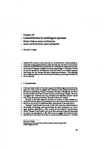
A hardware/equipment part able to physically influence the real world (e.g. a device, tool or other manufacturing unit, a transporter, or storage facility etc). A control part responsible for both the hardware/equipment part control and communications with the rest of the holonic community.” We note that the community may also include people to aid manufacturing decisionmaking. Interested readers are referred to Jarvis et al. [6] for an overview of the classic agent-based and holonic principles and the current state of the art in applying these principles to a range of manufacturing environments. As a consequence of trying to use this body of research to develop an agent-based manufacturing system demonstration, two critical technologies needed for making smart decisions have been identified: Automatic Identification (Auto ID) systems [20], and platforms for implementing autonomous agent and multi-agent systems [21]. Automatic identification (Auto ID) systems are used to read/write information to tags via high frequency radio waves. These electronic tags can replace barcodes and uniquely identify goods, thereby enabling decisions to be made by the agents on an item-specific level and removing the line-of-sight requirement when reading. Within the scope of this agent system, major aims of our ongoing research are: – To demonstrate that agent-based control can be integrated with the Auto ID infrastructure into manufacturing systems so the user has the ability to dynamically change how orders are made and managed [22]. – To show that flexible and robust operations can be achieved even when raw materials supply is random and varying, and order attributes regularly change. – To illustrate interactive order adjustment and dynamic modification of manufacturing operations in the case of errors and failure to satisfy quality control tests. – To fully exploit the potential agility and reliability of the physical system [23]. Answers to these questions will help companies to be more cost effective, to respond more quickly, and to form closer collaborative networks with both customers and suppliers, i.e. creating a virtual enterprise that spans several organisations for the manufacture of customised goods. Yet the consequence of this strategy is that business models need updating and manufacturing processes must be re-engineered to cope with the added complexity that agility demands. We define agility in this context as “the capability of the system, both in part and as a whole, to conduct business as usual in an environment where change is frequent and unpredictable”. Agents are a key technology to provide this agility. 4.3 An AMS Demonstrator at Cambridge University Agent Oriented Software Ltd. is working closely with the Centre for Distributed Automation and Control within the Institute for Manufacturing at Cambridge University to investigate how to best develop and deploy agent-based manufacturing solutions into industry. One strand of this investigation is to construct an agent-based manufacturing system demonstrator. Therefore the goal is to design, develop and integrate an agentbased packing cell to demonstrate how an agent-based manufacturing system offers more agility. The layout is shown in Figure 1 and the system is characterised by:
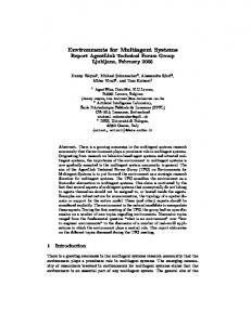
Business Problems There are three business questions to be addressed. First, how can consumable goods be packed together in a flexible way to meet specific and variable customer/retail needs? Second, what is the best way to use intelligent warehouse, production and packing resources in order to maximise efficiency in a factory where uncertainty, failures and changes are commonplace? Third, what is the best way for a product to decide how best to make, manage and deliver itself so that it is cost effective and satisfies the buyer’s requirements? Solution Agents are introduced onto the shop-floor to model both resources (e.g. conveyor shuttles, a robot, storage units) and products (gift boxes and items like razor blades). Every agent uses its own intelligence and interaction with others to determine how best to use facilities and get the orders packed effectively. The system enables the customer to select any three of four types of grooming product, pack them into one of two box styles, and change how their order should be packed on the fly. This solution is now more robust to changes in order requirements than conventional packing lines. Benefits The demand from customers for unique combinations of products to be packaged together has led to an examination of new control system technologies that will revolutionise the retail and production industries. Intelligent agents better utilise factory resources, make products more efficiently and so increase the reactivity of manufacturing businesses to changing market needs. Rush orders can buy packing services to get themselves made quicker, partially-packed orders can be broken down so that urgent orders can be made, resources can use market economies to ensure they are getting used optimally. This cell comprises a storage unit to hold items, a Fanuc M6i robot to move items throughout the cell, a MontrackTM shuttle conveyor to transport batches of raw materials (items) and the boxes into which items are to be placed around the cell. The plan view of the AMS system is given in Figure 2. The cell has three conveyor loops and independently controlled gates that guide shuttle navigation around the track. There are also two docking stations where shuttles are held so that the robot can pick and place items into the boxes that they carry. The system demonstrates many of the processes associated with agile manufacturing. Some agile/intelligent manufacturing scenarios that the cell demonstrates are: – Introduction of batch orders whereby individual products (i.e. boxes) manage their own resource allocation. This allocation includes acquiring a suitable tray, shuttle and items to accomplish the goal of packing that box. The system also negotiates with the docking stations to reserve a processing slot. – Docking stations cooperating to evenly distribute workload at runtime. – Handling of rush orders that must be packed earliest and how this influences the schedules of the docking stations and the other boxes to be packed. – The interaction between shuttles and gates to ensure routing of shuttles around the track is both shortest time and gives highest priority to urgent shuttles. – Failure of a docking station and how this resource change affects how and where shuttles are processed, fault tolerance and reconfiguration. – Organising a storage unit when the robot is no longer busy so that items of the correct types or most frequently used are located at the head of each chute.
Fig. 1. The Cambridge Agent-based packing cell
– Unpacking completed boxes so that urgent orders can be satisfied quickly.
4.4 Implementation of an AMS using JACKTM The implementation is a realisation of the above design ideas, constrained by: – The facilities offered by a specific agent development and execution environment. – The peculiarities of the physical hardware. – The lack of robust operations from its low-level support software that the agents rely upon. For instance, the inability to guarantee electronic product code (EPC) readings using radio-frequency (RF) tags with automatic identification (Auto ID) systems. – The inefficiency of the blackboard system [24] that interfaces to the Programmable Logic Controller (PLC) and robot. – The agent types that have been implemented in the control system (with the number of instances) are: Order Agent (an instance is spawned for each box ordered), Production Manager Agent (1 instance), Gate Agent (2 instances), Reader Agent (7 instances), Docking Station Agent (2 instances), Robot Agent (1 instance), Storage Agent (1 instance), Box Manager Agent (1 instance), and Track Agent (1 instance). Each of these agent types has been encoded as an agent using JACKTM . We focus now on the features of the robot agent because it is one of the more complex resource agents,
Resource
storage area
Product
docking station
robot
gate set 1
docking station
gate set 2
feeder loop quality control
Fig. 2. Layout of the cell
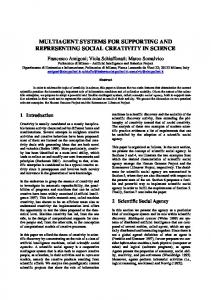
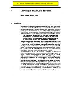
and its processing typifies the interactions an autonomous agent has within itself and with the external world. The robot agent supports the material handling functional objective via: – Scheduling jobs based on reward. – Performing various pick and place operations in order to pack boxes, unpacking boxes, sorting the storage area and unloading items into storage. – Interacting with the physical robot. Each of these is modelled as a JACKTM capability (containing appropriate events, plans and beliefsets) within the robot. The JDE Design Diagram in Figure 3 shows the components that make up a robot agent. The components are denoted as follows: (i) Agent – stick man in rectangle, (ii) capability – rectangle, (iii) plan – rounded rectangle, (iv) beliefset – cylinder, (v) event – envelope (shown in Figure 4). Consider an internal operation of the robot—the decision as to which pick and place action to perform. The S CHEDULE ROBOT plan (Figure 4) posts a ROBOT J OBA RRIVED event to itself, indicating that the robot should now execute a job (i.e. the one with the highest reward). Four plans in the P ERFORMING capability can handle this event. The choice as to which one will handle the event initially is determined at runtime using the context condition of these plans. The context condition filters on the basis of the number of items and boxes on a shuttle.
R
e
s
(
e
s
c
r
v
h
a
e
t
d
u
i
o
l
n
e
s
)
R
p
r
i
v
a
t
o
b
o
t
H
o
h
i
m
p
o
r
t
l
o
n
e
a
s
s
h
a
s
h
S
a
s
P
c
h
e
d
u
u
l
s
e
i
n
I
g
e
r
f
o
r
m
i
n
g
n
t
e
s
r
u
a
s
c
e
t
i
n
g
s
S
c
h
e
d
u
l
e
R
o
b
o
t
U
u
s
e
s
u
S
P
a
c
k
B
o
e
s
u
s
e
s
u
s
e
d
a
t
e
R
o
r
t
b
o
t
B
B
s
S
o
x
s
p
S
t
o
r
a
g
e
U
n
p
a
c
k
B
o
x
U
n
l
o
a
d
h
u
h
u
t
t
l
t
t
l
e
Fig. 3. JACK Design of Robot Agent
R
p
o
s
o
b
o
t
H
p
c
h
e
d
u
l
e
R
o
b
o
s
o
h
a
c
k
B
o
x
o
n
a
d
n
e
l
s
s
t
t
R
P
l
s
t
h
S
o
a
n
d
l
e
o
b
s
o
h
S
o
r
t
S
t
o
r
a
g
t
a
e
J
n
o
d
b
l
A
e
r
r
i
v
e
d
s
h
U
n
a
p
d
n
a
c
e
l
k
B
s
h
o
x
Fig. 4. Robot Agent’s Performance Interactions
a
d
n
U
l
n
e
s
l
o
a
d
S
e
G
Q
u
e
r
y
O
r
d
e
r
P
a
r
a
m
e
t
e
r
h
h
a
n
d
l
i
v
e
I
t
e
m
T
e
a
n
d
l
e
o
s
t
(
b
o
t
H
o
l
o
s
s
u
s
e
s
o
s
t
u
s
e
s
)
s
)
O
o
e
s
p
R
p
s
(
p
y
s
r
d
e
r
H
o
l
o
n
n
P
p
o
s
t
a
c
k
B
o
x
s
p
o
s
t
(
s
(
h
a
n
d
l
e
u
s
e
s
h
a
n
d
l
e
a
c
k
i
n
g
F
a
i
l
u
r
c
k
e
d
B
o
e
s
)
e
s
P
a
s
s
P
P
u
)
a
c
k
i
n
g
S
u
c
c
e
s
s
x
h
a
n
d
l
e
s
Fig. 5. Robot-to-Order Agent Interactions
Figure 4 illustrates this event/plan relationship. The remaining events handled and sent by the ROBOTAGENT have been removed from the figure for clarity. The interaction that an agent has with other agents is orchestrated through the exchange of messages. Again the JDE can be used to define these interactions. Figure 5 shows an example of such interaction between the robot and order agents. Explanation of the architectures and interfaces for the other agent types has been omitted for economy. The various agents interact with each other through the exchange of messages. These messages are either the offering of a service or requesting a service. An individual agent decides on what work to perform based on the value of the service less the cost of performing the work. In other words, agents prioritise work according to their estimated profit. This mechanism, while not necessarily producing optimal behaviour, allows many of the intricacies of the physical system, such as poorly performing robots or slow conveyors, to be modelled and dealt with efficiently. In addition, it allows external pressures, such as the need to handle rush orders, to influence each agent’s decision making. To coordinate the actions and decisions of agents, events are sent either synchronously or asynchronously. No agent is forced to process or reply to a message because each agent is autonomous but, generally speaking, good cooperation is encouraged by the agents responding to information requests with truthful data, and by executing appropriate plans to achieve the goals associated with incoming events.
Negotiation between the order agent and resource agents, as well as between resource agents (for fault tolerance), is managed solely in terms of price. The customer sets the price per box, when the batch order is placed via an e-manufacturing web page, and this price is used throughout the manufacturing process for sequencing the spawning of order agents, ’buying’ empty boxes/items, using a shuttle, reserving a slot in the docking station’s schedule, utilising the robot’s time and so forth. Hence demand and supply is matched in the course of the negotiation through a simple protocol: order agents in need of a particular service distribute requests to predefined instances of the resource agent class. The resource agents in turn evaluate the request in terms of their schedule and their status, and issue replies (bids) back to the order agent with the cost of the job. These costs are used by the order agent to select resources that are the cheapest. In classic agent design, this is viewed as awarding a contract. For example, having already secured the services of a shuttle holding the correct type of empty box, consider the negotiation between an order agent and the docking station agents to agree where that order’s empty box should be packed. The protocol proceeds as follows. The order agent announces to the loading docking station agent that it wants a job done and that the reward for undertaking this job is the price given by the customer. The docking station considers the job, by determining whether it can physically handle the shuttle and box. If the station is faulty, it returns a bid of infinite value. If not, it determines the slot into which the job would be placed. For instance, the existing schedule is shown in Table 1. Table 1. Initial Reservations in Docking Station Slot Shuttle EPC Reward 1 B00000000C000200A00D1704 $20 2 B00000000C000200A00D2645 $12 3 B00000000C000200A00D3199 $7
If a job worth $15 is requested, then the station could make an offer of Slot 2. Upon receiving this response, the order agent issues the same request to the unloading docking station agent, which will give a similar ’best slot’ reply. The order agent then evaluates both bids and selects the one with the earliest slot. The order agent informs the chosen station that it needs to book the named slot for its shuttle at the given price. The docking station inserts the tuple into its private reservation beliefset and so demotes other jobs whose rewards were lower. The order agents associated with these demotions are not informed of the sequence change; only the order agent of the newly inserted tuple is informed to confirm the deal. The order agent then informs the track agent to set the destination of the available shuttle to the selected docking station. Beyond responsiveness and the ability to cope with failed stations, this protocol has the merit that workload becomes evenly distributed across stations over time. This is an example of interaction between order and resource agents. Now consider another example, resource to resource interaction. When a shuttle
approaches a switch gate, it first passes a RF tag reader. The EPC of the tag attached to the shuttle is gained and processed by the Auto ID software system called the Savant and EPC Information System Server. A reader agent is regularly polling the server for the EPC of the last shuttle to enter the reader’s range. Upon arrival, the reader agent informs the appropriate gate agent of the shuttle’s presence. Each gate has two inputs and two outputs, and so the gate can decide which of two waiting shuttles to let through. This decision is currently made on a FIFO basis. The gate agent interacts with the track agent to determine the destination of the inbound shuttle and to determine if there is available space into which the shuttle can move. The track agent maintains a model of which shuttle is in what zone using a set of queues. The queue is added to when a shuttle enters a zone and popped when it departs. The track agent also keeps a model of the maximum number of shuttles that can be present in each zone (this is fixed at start-up and is tightly coupled with the track’s configuration). Hence the track agent is able to decide if another shuttle can enter a given zone based on the shuttle’s intended destination. If space is available then the gate agent is informed and so it can interact with the blackboard to set the hardware’s input/output choice and thus let the shuttle through. These are some of the typical agent interactions within the AMS. 4.5 Lessons from attempting to use JACKTM for Agent-based Manufacturing Using JACKTM agent system to control industrial automation equipment and to develop an automated manufacturing system taught us some valuable lessons about developing agent systems. These ranged from the importance of having a “yellow pages” directory for finding agents, to the value of logging mechanisms to help with understanding the dynamic aspects of a system. It is useful to have a standard yellow pages mechanism, such as that defined by FIPA, to provide a list of agents that provide a particular service. This is an important facility as it changes the way the agent classes are coded. For example, it makes it straightforward to add agent instances to cope with added hardware, effectively plugging in extra holons based on demand. Instead, in the current version, there was a tendency to name specific agent instances within the code for a generic agent class, thus limiting the generality of the class. Well-designed, and preferably standard, protocols are important for ensuring that inter-agent messages that need replies are replied to. Such protocols also help to avoid sending spurious replies that are not listened to. Although JACKTM catches these errors at runtime, the source of the problem can be difficult to track down. In addition, it is important to help the programmer think in high-level terms by providing abstract communication protocol support. For example, when one agent relies on another for a particular service, one way to communicate this requirement is the contract net protocol. We believe that the agent programming language and associated libraries should support this so that the programmer can simply say “get service X from any supplier of class C using the contract net protocol.” JACKTM does not directly support this feature at the time of writing. It is critical that synchronisation and mutual exclusion issues are handled correctly. JACKTM provides a powerful mechanism to help with these issues since most process-
ing for an agent is performed in a single thread, with the sequence of steps in a plan actually being implemented as a finite state machine (FSM). This ensures that each step in a plan is processed atomically. In addition, since JACKTM restricts the use of global data and encourages message passing between agents instead, there would seem to be less likelihood of encountering synchronisation issues. In fact, we found several instances of race conditions while debugging the system. Most of these were traced to updating JavaTM data structures over several plan steps, where JACK TM could interrupt processing between steps to give processing time to other plans. A key lesson was to move any data structure update statements to their own Java TM method to ensure that JACKTM treated them atomically. Another area that led to synchronisation problems was in the integration of legacy code. The code dealt with the task of communicating with a Programmable Logic Controller (PLC) by reflecting register memory inside the PLC and providing a mechanism to update it. This PLC communication system made use of an interaction protocol that was not robust to delays, and it was possible under some circumstances to miss the receipt of messages. Unfortunately, missing messages about the state of the registers could be catastrophic (as they were not stateless) and would eventually halt the operation of the control system. Simulation and emulation are key tools when developing physically instantiated control systems. Agent programming can be quite complicated. The overall behaviour of the system may not be what was expected and it is important to be able to (a) reproduce particular situations in a controlled environment in order to isolate and debug problems, and (b) rapidly test the system under a variety of conditions to prove robustness. We found that building an emulation of our physical environment that linked in with the JACKTM control system was worth the extra effort that it required and resulted in significant time savings. New approaches are required to simplify the process of debugging a multi-agent system. Although JACKTM is essentially Java-based, it can be cumbersome to try to debug JACKTM code using traditional JavaTM debugging environments. Instead, we found that logging tools, such as Apache’s Log4J, were useful in helping to isolate problems in particular areas of code. Log4J has the advantage that logging for individual JavaTM classes can be turned on or off without recompilation. We expect that recent additions to JACKTM , such as the agent message trace facility, will help with debugging agent systems in the future. As with object-oriented programming, it is important to clearly delineate the responsibilities of each entity [25]. For example, the idea of “containment” might be implemented by having the container knowing about all objects inside it, or alternatively, by having each contained object have a reference to the container (or possibly by a combination of both). Similarly, in part-oriented control [26], an agent representing the part is responsible for moving the part through the system and getting it machined or processed. An alternative is for resource agents to control the movements of parts. In an environment, such as ours, where several software engineers develop the system collaboratively, it is important that individual decisions about which tasks an agent should be responsible for make sense in terms of a larger picture. This approach is clearly well
aligned with the BDI paradigm in that to clearly understand and communicate how an agent should behave, it is useful to ascribe to it beliefs, intentions and desires. Real world events tend to be more noise-filled and more difficult to interpret than those occurring in idealised simulations. However filtering the noise from real world event data can be error prone. Incorrect filters may cause some events to be missed or additional events to be implied. Bugs in the event filtering may appear externally to be bugs in the reaction of agents. To avoid this, it is useful to keep an internal representation of the state of the world. This representation can then be used to debug the event filters independently of the agent’s reaction, by comparing the internal representation with the actual state of the world. Even though an agent might access this internal representation directly, it is still useful to provide event triggers to the agents, rather than have them poll for changes in the state of the world. We found that event triggers based on an internal world state representation could be more uniform than those produced by real world sensors, and this reduced the number of different plans required to handle them. For example, when a single part has just been packed into a gift box, this is similar to the arrival of a gift box with a single part that was packed previously. Both events require the next part to be packed, even though what has changed in the world is slightly different. The AMS has been successfully demonstrated to many visitors to the Cambridge automation laboratory, including a live demonstration via video link-up to a conference in Atlanta [30]. In the next section, we examine a quite different agent system, also created using JACKTM .
5 A Decision Support System Example: Meteorological Forecasting The Australian Bureau of Meteorology (BoM) is involved in an ongoing review of its information distribution systems. As part of that review the BoM is reassessing its forecasting and alerting capabilities. The BoM’s information environment is particularly complex, being both distributed and dynamic in nature [5]. These properties and previous experience led the BoM to choose a distributed multi-agent solution based on JACKTM [5]. The initial deployed system, known as “Intelligent Alerts” focused on a subset of aviation weather forecasting (air pressure forecasts), producing alerts to be displayed on forecasters’ desktops [27]. The system demonstrated a variety of desirable features such as extensibility, robustness in a changing environment and a reduction in the cognitive load on forecasters [27]. Extensions to the current system are underway including more comprehensive filtering of locations and alerts [28]. 5.1 Problem Definition and System Requirements The driving force for the Intelligent Alerts system was the umbrella project known as the Forecast Streamlining and Enhancement Project (FSEP). FSEP aims to improve quality, quantity, consistency and timeliness of weather products and services to both the general community and major BoM clients such as the aviation industry, fire fighters
and emergency services [5]. BoM customers require real-time alerting of major weather events. The aviation industry in particular requires rapid amendment of forecasts where current data suggests they may be inaccurate. Comparing weather conditions to forecast values can achieve this, however, due to the volume of data involved, the analysis must be automated. When the BoM sought a solution for their alerting needs, their environment had several factors that indicated a multi-agent system would provide an appropriate solution. The BoM is an information rich organisation dealing with a complex, evolving and distributed environment [5,27]. These factors are seen as the hallmark of domains in which multi-agent systems offer advantages over traditional solutions [28]. The BoM’s specific requirements included a system that is able to: – Evolve over time. The system was required to interoperate with existing systems in the short term, yet allow easy integration of future components. – Behave in a distributed, open and platform agnostic manner. The BoM operates in a heterogeneous network environment with forecasters using a diverse range of hardware and software. The BoM has offices across Australia and different groups within the BoM need to be able to deploy components of the system with minimal inter-group interaction. New components need to be located by other entities on the network and used appropriately [28]. – Handle large volumes of data produced by both agents and existing systems within the BoM. As mentioned above, the BoM is an information rich environment. For a system to operate effectively in such an environment, the solution had to scale gracefully as data volume increases. – Deal with a range of goals, some of which may at times conflict. The system had to be able to pursue multiple goals concurrently. Ideally resolution of contention between conflicting goals should be an automatic process. – Resolve inconsistencies in data where reports from different sources may conflict. The BoM has multiple sources of data describing similar phenomena. For example, multiple weather models are used within the BoM, all producing different predictions given the same set of initial values. The system had to deal with these types of inconsistencies and ambiguities. – Provide appropriate level of detail to users of the system. Alert pollution occurs when a user is inundated with such large amounts of information they begin to ignore all incoming alerts. In order to reduce the problem, the system had to make intelligent decisions before sending alerts to users. Users themselves would also be able to specify user-level alert filters based on their current information requirements. In addition to the close fit between multi-agent systems and the problem domain, the BoM had previous favourable experiences with agent systems used in the context of forecasting. Previous work by the BoM [29] used an agent-based system for detecting microbursts (regions of high-shear and strong down-drafts associated with thunderstorms that are considered hazardous to aircraft). The system’s results compared favourably with those of more complex solutions and indicated the usefulness of agents for solving problems within the BoM.
As mentioned above, the initial system targeted aviation forecasting and was restricted to the analysis of atmospheric pressure readings from automatic weather stations (AWS). This data was compared to Terminal Aerodrome Forecasts (TAFs), a forecast produced by the BoM related to conditions close to an airport. Inconsistencies between AWS data and TAF predictions may lead to an alert being sent to the forecaster. The TAF generation process allows for forecasters to issue forecast amendments. Hence alerts concerning inconsistencies are of particular interest to forecasters generating TAFs [5]. 5.2 Architecture The deployed system architecture is comprised of information routing agents, alerting agents, external data sources and alert viewing user interfaces. Figure 6 shows a JACKTM Design Tool diagram with an overview of the application showing a single alerting agent (the TAFMonitor).
T
A
F
M
o
n
i
t
o
r
s
s
e
n
d
h
D
a
t
a
S
t
r
e
a
m
u
O
t
u
p
t
a
n
d
D
l
a
e
a
n
d
l
e
d
b
b
d
t
S
a
s
h
e
n
s
d
s
e
y
t
n
r
e
a
m
I
n
u
p
S
t
u
b
s
c
r
i
p
t
i
o
n
C
o
n
t
r
o
l
s
d
y
h
D
a
t
a
S
t
r
e
a
m
D
i
s
p
a
c
t
T
h
e
(
h
t
i
e
D
e
r
w
n
d
l
e
b
d
y
r
e
x
v
e
a
a
n
t
a
T
a
l
C
l
S
y
t
v
P
r
i
M
e
a
m
a
D
a
e
s
i
T
s
a
s
C
g
p
P
e
a
t
s
C
c
o
o
h
c
n
e
k
n
r
e
e
i
n
t
i
o
n
e
r
a
c
t
s
t
c
t
)
Fig. 6. Overview of the BoM Application Design
A TAFMonitor agent monitors terminal area forecasts comparing them to AWS readings of currently observed values. A DataStreamDispatcher agent is responsible for message routing and subscription control within the system. Entities subscribe to data feeds provided through the DataStreamDispatcher using SubscriptionControl events. Producers send data to the DataStreamDispatcher (via DataStreamOutput events), which
then routes that data to Subscribers via DataStreamInput events. The TAFMonitor agent acts as both a subscriber (to the AWS and TAF data streams) and a producer of data in the form of TAF alert messages. In addition to the event delivery paths shown in Figure 6, the DataStreamDispatcher agent is also able to route messages sent across standard TCP streams, allowing integration with non-agent legacy systems. The AWS data stream is delivered into the system via this pathway. The Alert GUI, which subscribes to the Alerts generated by the TAFMonitor agent, is not depicted in this figure. This architecture, with its relatively small number of components (many of which contain only several lines of code), exemplifies the tendency for agent-based solutions to produce relatively concise solutions to complex problems. 5.3 Implementation JACKTM was chosen as the agent platform for the Intelligent Alerts system. JACK’s embodiment of BDI concepts was seen as central to its suitability for this project. The ability to deal with a rapidly changing world, the fact that the system can affect the world (through the amendment of forecasts) and the ability to have reactive and goaldirected behaviour, all proved useful attributes in the deployed system [27]. Initially the TAFMonitor agent produced alerts when a 2 hectopascals (hPa) difference between TAF predicted air pressure and AWS observations occurred. As part of an overall strategy to avoid alert pollution, an alert is only produced if the difference becomes larger than the previous difference plus a given margin [27]. The Intelligent Alerts user interface (UI) was an important part of the system. As the interface between the underlying architecture and the forecaster or forecast consumer, it was important that the UI improved the productivity of the end-user rather than adding another task to their workload. As such, the UI was designed to require as little user interaction as possible, whilst allowing enough configurability to tailor data feeds to those most relevant to the individual user. The ability to drill down into summary data for more details when required was seen as essential in reducing the cognitive load on the user. 5.4 Strengths of the Current System The initially deployed system provides an end to end demonstration of all the functional requirements of the system, that is, subscriptions, data routing, data source communication, self-describing data, service description and location mechanisms. In addition to the systemic advantages provided by the BDI, multi-agent approach previously mentioned, the deployed system exhibited the following specific advantages, as highlighted in [5,27]: – Post-Hoc feedback to the forecaster, after the period of validity for the forecast has expired, allows the forecaster to see how close to actual conditions their forecast came. – The automation of delivering alerts to external consumers of meteorological data means forecasters are able to concentrate on analysis during extreme weather conditions rather than the dissemination of information to interested parties.
– Easy extensibility with volcanic ash alerts. As a test for system flexibility, a new alert type was added incorporating Volcanic Ash warnings from the Volcanic Ash Advisory Centre (VAAC). BoM developers subscribed to a VAAC email list for volcanic ash alerts and fed the alerts into a JavaTM process that delivers them in XML format to an Ash Alerts agent. Subscribers to the Ash Alert agent were able to view the content of the email in their alert GUI. This addition took less than 2 person days of development—an indication of the ease with which the current system could be extended. – The use of a publish/subscribe paradigm allowed agents to be added and removed easily from the system. After the replacement of a subscriber, the new entity automatically re-subscribes to its relevant data feeds. Similarly, when a data publisher is replaced or restarted, any subscribers automatically re-subscribe to the publisher. This type of self-healing is important in a distributed system where manual intervention is neither desirable nor practical. – JACKTM provided a flexible implementation platform allowing for the rapid development of new plans to deal with new situations. Using JACKTM capabilities allowed the re-use of related clusters of behaviour between agent types. The rapid development (2 days) of the Volcanic Ash agent indicates the level of flexibility provided by the JACKTM platform. – The use of code-independent data structures such as XML allows data structure extension without recompilation. 5.5 Future Directions Whilst the system in its current form performed well in the environment it was designed for, as the system evolves to embrace a larger subset of the BoM’s information flow, it will require various extensions. Most obvious is the inclusion of a wider variety of data sources leading to an increase in the types of alerts available on the system. As the number and diversity of alerting agents grows, the need to design new agents, and understand and use the new services they provide, will increase. Work is currently underway on both these fronts in a new collaboration between the RMIT Agents Group, the BoM and Agent Oriented Software [28]. A powerful alert filter definition language will also prove more important. As the number of alerts in the system increases, users will require a system with a sufficiently expressive mechanism for defining the alerts they deem to be salient.
6 Discussion We believe that JACKTM is an important and novel contribution to the field of agentoriented software engineering. Rather than invent a new language, an existing popular language (JavaTM ) has been augmented with constructs for agent communication, knowledge representation, and for both deliberative (goal-based) and reactive (eventbased) programming. This has been achieved in a way that allows the programmer to mix familiar JavaTM statements with agent programming constructs. Although JACKTM is strongly oriented toward the BDI paradigm, its component-based architecture supports a wide variety of agent programming styles.
The JACKTM language is supported by an integrated development environment (IDE) that allows the programmer to layout the structure of an agent application using a graphical interface, and this has been important in involving Subject Matter Experts in the development process. Experience with developing systems involving multi-agent coordination led to the addition of JACK Teams, which provides a general framework for team-based agent coordination. Together with JACK Sim, these tools provide a rich environment for agent-oriented software development. A simple way to demonstrate the suitability of JACKTM (and possibly of agent programming in general), is to examine cases where JACK TM has been used in industry. In this chapter we have examined two industrial applications of JACKTM —an Agent-based Manufacturing System (AMS) and a meteorological alerting decision support system. The AMS was a sizeable development effort and involved integration with complex physical systems and interfacing with legacy code. Not surprisingly, there were a number of general lessons learnt about how to construct such agent systems, and some more specific lessons about how to make best use of JACKTM . The general lessons related to the importance of standard protocols and services, such as those proposed by FIPA, the usefulness of simulation or emulation, particularly when dealing with robotic systems, and the importance of clearly defining roles and responsibilities when designing each agent and their interaction with other agents. In terms of specific lessons about JACKTM , we found that understanding how JACKTM converts plan steps into a finite state machine helped with debugging some problems involving synchronisation—particularly where JavaTM native data structures were used. Also, we found that logging and message traces were useful tools when diagnosing problems with dynamic aspects of the system. The AMS system was developed with a Holonic framework [17,19] in mind, rather than a BDI one. An advantage of JACKTM is that it is sufficiently flexible to allow this. In addition, the ability to be proactive, alongside an event driven, reactive structure, was an important feature, and allowed the behaviour of the system to be more sophisticated than if it had been purely reactive. However, from the work on this system so far, it is not clear whether a BDI approach would be more suitable. The Intelligent Alerts meteorological forecasting system provides real-time alerts of significant changes in weather data, allowing the forecaster to provide the aviation industry with timely warnings of impending shifts in climate. The ability to integrate with legacy forecasting systems was a key prerequisite. JACK’s implementation as an extension of JavaTM allows it to leverage all of the capability of that language and greatly facilitates integration with legacy software systems. This factor cannot be overemphasised—if they are to be adopted by industry, multi-agent systems must be no more difficult to integrate than conventional software. The agent-oriented BDI architecture of the Intelligent Alerts system provided benefits that are characteristic of the approach. Perhaps most important was the ability to mix reactive and proactive modes of behaviour and deal with multiple concurrent goals. At times, the weather is in a state of high flux, thus it is vital that the Intelligent Alerts system can react to these changes in the context of its long-term desires, such as to not flood the user with alerts. The two applications of JACKTM described in this chapter would have been difficult to implement outside of the multi-agent paradigm. Decomposing each application into
a collection of autonomous agents, each motivated to fulfil its role in the system, greatly reduced the complexity of the undertaking. Although functional decomposition is not new, the encapsulation of functionality within autonomous computational entities is a relatively novel approach in industry. In addition, the BDI paradigm is a useful abstraction when thinking and communicating about how such autonomous entities should behave. Based on our experience of the successful commercial application of JACKTM in dynamic, distributed domains, it is our belief that multi-agent systems have come of age and will be more widely adopted by industry in the near-term.
Acknowledgements The Meteorological Forecasting Decision Support System was a collaborative project between Agent Oriented Software Ltd., the Australian Bureau of Meteorology and the RMIT Agents Group in Melbourne, Australia. The work was supported by an Australian Research Council Linkage Grant (grant LP0347025, “Open agent architectures for intelligent distributed decision making”). We thank Jeff Schultz and Ralph Rönnquist for their valuable comments on earlier drafts of this chapter. We would also like to thank the anonymous reviewers for their insightful suggestions and comments.
References 1. d’Inverno, M., Kinny, D., Luck, M., Wooldridge, M.: A formal specification of dmars. In Singh, M., Rao, A., Wooldridge, M., eds.: Intelligent Agents IV: Proceedings of the Fourth International Workshop on Agent Theories, Architectures, and Languages. Volume LNAI 1365., Springer-Verlag (1998) 155–176 2. Rao, A.S., Georgeff, M.P.: BDI agents: From theory to practice. In: Proceedings of the First International Conference on Multi-Agent Systems (ICMAS-95), Menlo Park, California, AAAI Press (1995) 312–319 3. Wooldridge, M.: Reasoning about Rational Agents. MIT Press (2000) 4. Agent Oriented Software: Human variability in computer generated forces (HV-CGF). http://www.agent-software.com/shared/solutions/hvcgf.html (2003) 5. Dance, S., Gorman, M.: Intelligent agents in the Australian Bureau of Meteorology. In: Challenges in Open Agent Systems Workshop, in Autonomous Agents and MultiAgents Systems (AAMAS02), Bologna, Italy (2002) 6. Jarvis, D., Jarvis, J., Lucas, A., Rönnquist, R., McFarlane, D.C.: Implementing a multi-agent system approach to collaborative autonomous manufacturing operations. In: Proceedings of IEEE International Conference on Systems Man and Cybernetics. (2001) 7. Ljungberg, M., Lucas, A.: The OASIS air-traffic management system. In: Proceedings of the Second Pacific Rim International Conference on Artificial Intelligence, PRICAI ’92, Seoul, Korea (1992) 8. Bratman, M.E.: Intention, Plans, and Practical Reasoning. Harvard University Press, Cambridge, MA (USA) (1987) 9. Georgeff, M.P., Ingrand, F.F.: Monitoring and control of spacecraft systems using procedural reasoning. In: Proceedings of the Space Operations Automation and Robotics Workshop, Melbourne, Australia (1989)
10. Murray, G., Steuart, S., Appla, D., McIlroy, D., Heinze, C., Cross, M., Chandran, A., Raszka, R., Rao, A.S., Pegler, A., Morley, D., Busetta, P.: The challenge of whole air mission modelling. In: Proceedings of Australian Joint Conference on Artificial Intelligence AI ’95, Melbourne, Australia (1995) 11. Lucas, A., Rönnquist, R., Ljungberg, M., Howden, N., Corke, P., Sikka, P.: Teamed UAVs— a new approach with intelligent agents. In: 2nd AIAA "Unmanned Unlimited" Systems, Technologies, and Operations—Aerospace, Land, and Sea Conference. (2003) 12. Fikes, R., Nilsson, N.: Strips: A new approach to the application of theorem proving to problem solving. Artificial Intelligence 2 (1971) 189–208 13. Bratman, M.E., Isreal, D.J., Pollack, M.E.: Plans and resource-bounded practical reasoning. Computational Intelligence 4 (1988) 14. Georgeff, M.P., Lansky, A.L.: Procedural knowledge. In: Proceedings of the IEEE Special Issue on Knowledge Representation 74. (1986) 1383–1398 15. Agent Oriented Software: JackTM manual. http://www.agentsoftware.com/shared/demosNdocs/JACK_Manual.pdf (2003) 16. Ingrand, F.F.: C-PRS Development Environment (Version 1.4.0). ACS Technologies, Labege Cedex, France. (1994) 17. Bussmann, S., Sieverding, J.: Holonic control of an engine assembly plant—an industrial evaluation. In: Proceedings of the IEEE International Conference on Systems, Man, and Cybernetics, Berlin, Springer-Verlag (2001) 169–174 18. Koestler, A.: The Ghost in the Machine. Arkana (1967) 19. Maˇrík, V., Fletcher, M., Pˇechouˇcek, M.: Holons and agents: Recent developments and mutual impacts. In: Multi-Agent Systems and Applications II. Number 2322 in LNAI, Heidelberg, Springer-Verlag (2002) 20. Sarma, S., Brock, D.L., Ashton, K.: The networked physical world—proposals for engineering the next generation of computing, commerce and automatic identification. Technical Report MIT-AUTOID-WH-001, MIT Auto-ID Center (2000) 21. Suda, H.: Future factory system in Japan. Journal of Advanced Automation Technology 1 (1989) 22. Brussel, H.V., Bongaerts, L., Wyns, J., Valckenaers, P., Ginderachter, T.A.V.: Conceptual framework for holonic manufacturing: Identification of manufacturing holons. Journal of Manufacturing Systems 18 (1999) 23. Vrba, P., Hrdonka, V.: Material handling problem: FIPA compliant agent implementation. In: Proceedings of the Twelfth International Workshop on Distributed and Expert Systems Applications DEXA. (2001) 635–639 24. Chirn, J.L., McFarlane, D.C.: Building holonic systems in today’s factories: A migration strategy. Journal of Applied System Studies 2 (2000) special issue on Holonic and MultiAgent Systems. 25. Beck, K., Cunningham, W.: A laboratory for teaching object-oriented thinking. SIGPLAN Notices 24 (1989) 26. Kärkkäinen, M., Holmström, J., Främling, K., Artto, K.: Intelligent products—a step towards a more effective project delivery chain. Computers In Industry 50 (2003) 141–151 27. Dance, S., Gorman, M., Padgham, L., Winikoff, M.: A deployed multi agent system for meteorological alerts. In: Deployed Applications of Autonomous Agents and Multiagent Systems Workshop, AAMAS03, Melbourne, Australia (2003) 19–26 28. Mathieson, I., Dance, S., Padgham, L., Gorman, M., Winikoff, M.: An open meteorological alerting system: issues and solutions. In Estivill-Castro, V., ed.: Proceedings of the 27th Australasian Computer Science Conference. Volume 26 of Conferences in Research and Practice in Information Technology., The University of Otago, Dunedin, New Zealand (2004) (to appear).
29. Dance, S., Potts, R.: Microburst detection using agent networks. Journal of Atmospheric and Oceanic Technology 19 (2002) 646–653 30. Brusey, J., Fletcher, M., Harrison, M., Thorne, A., Hodges, S., McFarlane, D.: Auto-id based control demonstration phase 2: Pick and place packing with holonic control. Technical Report CAM-AUTOID-WH-011, Auto-ID Center (2003) http://www.autoidlabs.org/researcharchive.