Published in Optical Fabrication & Testing 2004, Topical Meeting of the Optical Society of America, Rochester, NY, October 2004, paper OTuB3.
Improved optical metrology using phase retrieval Gregory R. Brady
The Institute of Optics, University of Rochester, Rochester, NY 14627 TEL: (585) 273-5991 FAX: (585)244-4936 EMAIL:
[email protected]
James R. Fienup
The Institute of Optics, University of Rochester, Rochester, NY 14627
Abstract: The use of phase retrieval presents opportunities for greatly simplifying the techniques and apparatus used for characterizing optical surfaces and systems, particularly aspherical surfaces. We describe the method and some early results. 2004 Optical Society of America
OCIS codes: (120.5050) Phase measurement; (120.3940) Metrology; (100.5070) Phase retrieval; (070.2580) Fourier optics; (050.1960) Diffraction theory
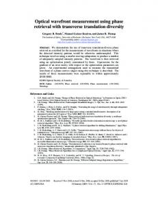
1. Introduction It is well known that the use of aspheric surfaces on lenses and mirrors in optical systems can result in superior performance over using spherical surfaces alone. The performance arises due to the lower aberrations inherent in certain aspheric shapes and the additional degrees of freedom they provide in the design process [1]. However, the manufacture of aspherical shapes is much more difficult than spherical shapes. Much of the difficulty arises from the increased difficulty in measuring aspheric surfaces [2]. The main challenge of conventional aspheric metrology is producing a suitable aspheric wavefront to be used to test the surface in a null configuration in an interferometer. The most common approach involves using specially designed multi-element refractive/reflective null lenses [3], or specially designed diffractive elements (computer generated holograms) [4]. The design and fabrication of these null elements themselves requires significant effort and expense. When the null element is used to test the surface in an interferometer, deviations in surface shape from the nominal are easily measured. A metrology technique that eliminates the need for a null element is an attractive alternative. A technique that eliminates the need for the interferometer itself would be even more attractive. Techniques such as contact profilometry or Shack-Hartmann wavefront sensing meet this criteria. However, these techniques may be limited by dynamic range, spatial resolution, or accuracy of the measurement; and they employ moderately complicated apparatus. Phase retrieval can potentially measure the surface with comparable accuracy, spatial resolution, and dynamic range as conventional interferometry, and is capable of testing a much more general class of surfaces. Phase retrieval achieves this while using a minimum of equipment, as illustrated in Figure 1.
Piece under test Display of wave front distortion
Computer
Illumination Wave front CCD Array measures intensity of reflected wave front
Figure 1: The measurement approach for phase retrieval. It is possible that the measurements can be made with no additional optics whatsoever, in reflection or transmission.
2. Summary of phase retrieval Interferometry produces a fringe pattern that is reasonably simple to interpret, but requires additional optics to produce it. In contrast, phase retrieval uses the absolute minimum of optics, but must perform a more difficult
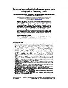
interpretation of the resulting measurements. The measurement path is entirely common-path, so the measurement is inherently tolerant of vibration and turbulence effects that degrade the accuracy of interferometry. The measurement approach is illustrated in Figure 1. We illuminate the surface with a wavefront of known shape in such a way that the resulting beam converges to a small enough area in some plane as to be collected by a detector array, such as a CCD. Interpretation of the measured intensity is not at all obvious, but can be accomplished by phase retrieval algorithms [5, 6]. These algorithms have been used successfully in the past for wavefront sensing for adaptive optics and for diagnosing the aberrations of the Hubble Space Telescope [7]; NASA is planning on using phase retrieval algorithms for aligning the segments of the James Webb Space Telescope. While the algorithms have been used successfully before, they have not been sufficiently developed to make them generally useful as an optical metrology tool. Phase retrieval can generally be approached as an optimization problem. The algorithms involve precisely modeling the diffraction propagation of the wavefront from the part under test to the detector using common propagation techniques such as Fraunhofer or Fresnel transforms [8]. Once the propagation is modeled, an iterative algorithm is employed to arrive at an estimate of the wavefront. These algorithms might include the iterative transform (Gerchberg-Saxton) or nonlinear optimization (gradient search) algorithms [5, 6]. 3. Preliminary simulation results A numerical simulation of phase retrieval employed in an optical metrology application has been performed. The particular situation modeled was that of a refractive microlens with a diameter of 250 µm and focal length of 500 µm. A schematic of the arrangement modeled is shown in Figure 2. The intensity was measured at two planes separated axially. The use of multiple intensity measurements increases the robustness and helps to ensure that the algorithm converges. Different amounts of aberration (in the form of Zernike polynomials) were added to the surface. Intensity patterns were calculated from the phase distribution using a discrete version of the angular spectrum approach [8], given by
[(
)]
U ( pd x , qd y ; z ) = IDFT DFT U md x , nd y ; z = 0 exp iz k 2 − 4π 2
p
2
Md x
+ q
2
Nd y
(1)
where p and q are the sample numbers in the x- and y-directions in the output plane, m and n are the sample numbers in the x- and y-directions in the input plane, dx and dy are the sample spacings (same in both planes), U(x,y;z) is the complex scalar field in the z plane. DFT and IDFT represent the forward and inverse Fourier transform operations, computed using an FFT.
φ=250 µm f=500 µm
z=333 µm
z=667 µm
Figure 2: Schematic of the measurement modeled in simulation, for lens of diameter 250 µm, and focal length 500 µm
The resulting intensity distributions were the input to the phase retrieval algorithm. In this case the algorithm was a gradient search routine that found the Zernike polynomial coefficients that described the wavefront producing
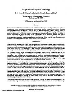
the input intensity patterns. This algorithm was chosen because it is simple to calculate the gradient of an error metric with respect to all of the Zernike coefficients using just a few propagation operations. An example computation is shown in Figure 3. The input phase was computed using the Zernike polynomials up to 5th order (21 polynomials.) Each Zernike polynomial was multiplied by a uniform coefficient of 5.8 radians and summed to form the phase distribution. The resulting intensity distributions are shown in Figure 3(b) and (c).
(a)
(b)
(c)
(d)
Figure 3: Results of a numerical simulation of a phase retrieval algorithm. (a) Wrapped phase map of the phase distribution of the surface under test. (b), (c) Intensity patterns computed in planes z1=333µm and z2=667µm from the surface being tested (opposite sides of the focus.) (d) Wrapped phase map of the retrieved phase distribution.
The retrieved phase distribution is shown in Figure 3(d). The agreement between this and the initial phase distribution is excellent. The error between the true and the retrieved Zernike coefficients was on the order of 10–7 radians of phase. While this result is very encouraging, we must point out that the simulation was conducted without factoring in the affects of measurement or quantization noise in the data. Further work will address these issues. 4. Conclusion Phase retrieval is a promising tool for optical metrology that could prove to be very useful due to the simplicity of the apparatus that it requires and the variety of surface and systems that it could be used to measure. Preliminary simulation results neglecting measurement noise show that essentially the exact wavefront can be recovered just by measurements of intensity. Further work is needed to develop this technique into a practical tool for optical shop testing. 5. References [1] Warren J. Smith, Modern Optical Engineering, 3rd Ed. (McGraw-Hill, New York, 2000). [2] Milton Laikin, Lens Design, 3rd Ed. (Marcel Dekker, New York, 2001). [3] A Offner and D. Malacara, “Null Tests Using Compensators”, in Optical Shop Testing, 2nd Ed., D. Malacara, ed. (Wiley, New York, 1992). [4] J.C. Wyant and V.P. Bennett, “Using Computer Generated Holograms to Test Aspheric Wavefronts”, Appl. Opt. 11 28332839, (1972). [5] J.R. Fienup, “Phase Retrieval Algorithms: A Comparison,” Appl. Opt. 21, 2758-2769 (1982). [6] J.R. Fienup, “Phase-Retrieval Algorithms for a Complicated Optical System,” Appl. Opt. 32, 1737-1746 (1993). [7] J.R. Fienup, J.C. Marron, T.J. Schulz, and J.H. Seldin, “Hubble Space Telescope Characterized by Using Phase Retrieval Algorithms,” Appl. Opt. 32, 1747-1768 (1993). [8] Joseph W. Goodman, Introduction to Fourier Optics, 2nd Ed. (McGraw-Hill, New York, 1996).