Improved Power Conditioning System of Micro-Hydro Power Plant for Distributed Generation Applications Marcelo G. Molina1, Mario Pacas2 1
CONICET, Instituto de Energía Eléctrica, Universidad Nacional de San Juan, J5400ARL, San Juan, Argentina 2 Institute of Power Electronics and Electrical Drives, Universität Siegen, D-57068, Siegen, Germany E-mail:
[email protected]
Abstract- A small-scale hydropower station is usually a run-ofriver plant that uses a fixed speed drive with mechanical regulation of the turbine water flow rate for controlling the active power generation. This design enables to reach high efficiency over a wide range of water flows but using a complex operating mechanism, which is in consequence expensive and tend to be more affordable for large systems. This paper proposes an advanced structure of a micro-hydro power plant (MHPP) based on a smaller, lighter, more robust and more efficient higher-speed turbine. The suggested design is much simpler and eliminates all mechanical adjustments through a novel efficient electronic power conditioning system (PCS) for connection to the electric grid. In this way, it allows obtaining higher reliability and lower cost of the power plant. Moreover, a full detailed model of the MHPP is derived and a three-level control scheme is designed, comprising a full decoupled current control strategy in the synchronous-rotating d-q reference frame. The dynamic performance of the proposed systems is fully validated by digital simulation carried out by using SimPowerSystems of MATLAB/Simulink.
I.
INTRODUCTION
In the last decade, problems related to energy factors (oil crisis), ecological aspects (climatic change), electric demand (significant growth) and financial/regulatory restrictions of wholesale markets have arisen worldwide. These difficulties, far from finding effective solutions, are continuously increasing, which suggests the need of technological alternatives to assure their solution. One of these technological alternatives is named distributed generation (DG), and consists on generating electricity as near as possible of the consumption site, in fact like it was made in the beginnings of the electric industry, but now incorporating the advantages of the modern technology [1]. Here it is consolidated the idea of using clean non-conventional technologies of generation that use renewable energy sources (RESs) that do not cause environmental pollution, such as wind, photovoltaic, hydraulic, etc. [2]. Recently, a rising interest on grid integration of micro-hydro power plants (MHPPs) has emerged, mainly because they are a proven technology with a very good performance and feasible with low investment costs, resulting in the technology based on RESs with smaller costs even when are compared to wind
978-1-4244-5697-0/10/$25.00 ©2010 IEEE
generation [3]. This trend is expected to be increased even more due to the high potential of application of MHPPs in DG and to the large amount of benefits for the use of renewable energy sources. These benefits include favorable incentives in many countries and the retributions coming from trading carbon emission reduction (CER) credits that impact in the commercial acceptance of the technology. A small-scale hydro power station (from pico to mini-hydro power plants) is usually a run-of-river plant that uses a fixed speed drive with mechanical regulation of the turbine water flow rate through adjustable guide vanes and runner blades for controlling the active power generation. This double-regulated design enables to reach high efficiency over a wide range of water flows but using a complex operating mechanism, which is in consequence expensive and tends to be more affordable for large-scale systems. This paper proposes an advanced structure of a MHPP based on a smaller, lighter, more robust and more efficient higherspeed turbine. The suggested design is much simpler and eliminates all mechanical adjustments through a novel electronic power conditioning system (PCS) for connecting to the electric distribution grid, as depicted in Fig. 1. In this way, this topology allows obtaining higher reliability and lower cost of the power plant. A full detailed model of the MHPP is derived and a new three-level control scheme is designed. The model includes a run-of-river hydraulic turbine directly coupled to a synchronous generator and the PCS is made up of an AC/DC/AC static converter. The control consists of a multilevel hierarchical structure and incorporates a maximum power point tracker (MPPT) for better use of the hydro resource. In addition, reactive power compensation of the electric grid is included, operating simultaneously and independently of the active power generation. The dynamic performance of the proposed control schemes is completely validated through digital simulation carried out by using MATLAB/Simulink. II. MODELING OF THE MICRO-HYDRO POWER PLANT The proposed hydropower station is a run-of-river plant which consequently does not have any significant water reservoir such as large dams. Only a fraction of the available
1733
The hydraulic turbine implemented and characterizated in the laboratory is a 350 W rated power one designed for an average 1.5 m head and a water flow rate of 35 l/s. Fig. 1 describes the whole arrangement employed for studying the proposed turbine. The hydraulic turbine model is obtained from its steady-state characteristics, assuming water to be incompressible. The output hydraulic power available from the hydraulic turbine is given as follows [4]: Phyd = ρ g H Q , (1)
Fig. 1. Layout of the implemented MHPP.
stream flow at a given time is used, this leading to a good agreement with the environment and permitting the utilization of low head water sources for DG applications. In order to allow extended control features when they are integrated into the electric power grid and also to provide the enough flexibility to adapt to the specific conditions of rivers with low water flow rate, a variable speed turbine is proposed to use in this work. Thus, by optimizing the turbine working point in order to extract the maximum power of the water flowing per second, superior efficiencies respect to traditional hydro turbines can be obtained. Moreover, by replacing mechanical controls with advance technologies in power electronic devices, higher reliability stations with better efficiencies can be reached. The modeling approach of the proposed micro-hydro power plant is based on the structure of Fig. 1. The MHPP consists of a variable speed micro-hydro turbine directly coupled to a permanent magnet synchronous generator (PMSG) and connected to the electric grid through an advanced power conditioning system (PCS). The proposed PCS is composed of a three-phase rectifier bridge, and an impedance-fed DC/AC power inverter. A. Hydraulic Turbine Characteristics The proposed hydro power is a basic reaction turbo-machine well suited for low water heads and low water flow rates. This hydraulic turbine is a propeller type, modified from a Kaplan turbine with neither blade pitch control nor upstream guide vane one. In addition, the turbine does not implement a gear box for coupling to the generator which yields a simple and robust design. The turbine is a vertical axis machine with a spiral case and a radial guide vane configuration. The water flow enters in a radial way inward and makes a right angle turn before entering the runner in an axial direction. The turbine design is made with an optimum water swirl before entering the turbine runner through appropriate guide-vanes setting, so as to obtain the best efficiency for the rated power.
being ρ the specific density of water (1000 kg/m3 at approximately 4 ºC), g the acceleration due to gravity (9.8 m/s2), H the water net head (m) and Q the water flow rate or discharge (m3/s). The potential energy in water is converted into mechanical energy in the turbine as a result of the water pressure which applies a force on the face of the runner blades and then decreases as it passes through the reaction turbine. The relation between the mechanical and the hydraulic powers can be obtained by using the hydraulic turbine efficiency ηh, as expressed in (2). Pm = η h Phyd , (2) Since the proposed hydraulic turbine can operate over near all the range of rotor speeds, the assumption of linear torque versus speed characteristic (at a given rated water flow per second and water head) cannot be used, as usually considered in the literature. As a result, the mechanical power characteristic could not be considered simply a parabola (as typically) [4, 5]. Indeed, the hydraulic turbine efficiency that yields Pm is highly dependent of the turbine design and operating conditions (Q, H, and the angular speed of the turbine rotor ω), and thus is very complex to be analytically determined. Consequently, numerical approximations have been developed in this article to calculate the mechanical power characteristic of the implemented hydraulic turbine and an expression of ηh as a function of Q and ω has been proposed and validated in the laboratory by a static behavior test. ⎡ 1 ⎛ 90 ⎞ ⎛ − 50 ⎞⎤ ⎟⎥ (3.33 Q) , (3) ηh (λ, Q) = ⎢ ⎜⎜ + Q + 0.78⎟⎟ exp⎜⎜ ⎟ ⎠ ⎝ λi ⎠⎦⎥ ⎣⎢ 2 ⎝ λi −1
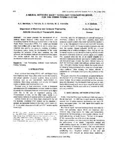
⎛ RAω ⎞ ⎡ ⎤ 1 ⎟⎟ , − 0.0035⎥ and λ = ⎜⎜ (4) with λi = ⎢ ( ) λ + 0 . 089 ⎣ ⎦ ⎝ Q ⎠ being R the radius of the hydraulic turbine blades (m) and A the area swept by the rotor blades (m2). Fig. 2 illustrates the steady-state mechanical power characteristic function Pm versus the rotating-speed of the hydraulic turbine ω at various constant water flow rates Q, with H fixed at 1.5m. The point of optimal efficiency is designed to be at rated water flow rate and head, where the turbine captures the maximum power. It can be observed that, for each water flow rate, there exists a specific point in the hydraulic turbine characteristic where the output mechanical power is maximized, aka maximum power point (MPP). Thus, the control of the
1734
Fig. 2. Mechanical power vs. rotor speed curves measurements and simulations at various water flow rates for the studied hydraulic turbine.
turbine rotor results in a variable-speed operation aiming at tracking the MPP for the particular operating conditions such that the maximum power can be extracted continuously from the water. B. Power Conditioning System The power conditioning system used for connecting RESs to the distribution grid requires the flexible, efficient and reliable generation of high quality electric power [6]. The PCS proposed in this work is depicted in Fig. 3, and is composed of a back-toback AC/DC/AC converter that fulfills all the requirements stated above. Since the variable speed hydro turbine is directly coupled to the synchronous generator, this later produces output voltages with variable amplitude and frequency. This condition demands the use of an extra conditioner to meet the amplitude and frequency requirements of the utility grid. A three-phase uncontrolled full-wave rectifier bridge is proposed here for performing the AC/DC conversion. This device has the benefit of being simple, robust, cheap, and needs no control system. On the other hand, a three-phase DC/AC voltage source inverter (VSI) using IGBTs is employed for connecting to the grid. As the power rating of the inverter for DG applications is generally in the order of kWs, the output voltage control of the VSI can be achieved through pulse width modulation (PWM) techniques. The connection to the utility grid is made through a step-up transformer and a low pass filter in order to reduce the
perturbation on the distribution system from high-frequency switching harmonics generated by the PWM control. As the VSI needs a fixed DC link in order to allow a decoupled control of both active and reactive powers exchange with the electric grid, an interface in the DC side of the VSI is required. For this purpose, an intermediate DC/DC converter (or chopper) in a boost topology can be used [7], thus allowing linking the output of the full-wave rectifier bridge to the DC bus of the inverter using only one switching device. This arrangement of rectifierchopper allows replacing the conventional six-pulse voltage source inverter employed in the rectifier mode, while resulting in a lower cost and simpler control. This two-stage configuration represents a good solution in terms of greatly reducing the inverter current rating and hence the cost of the whole system. However, still retains some disadvantages when compared to single-stage topologies: • Reduced power conversion efficiency: because of the twostage configuration (DC/DC boost converter and DC/AC inverter), which inevitably reduces the power conversion efficiency. • Reduced reliability: because more components are used in this configuration with the addition of the chopper. • Higher volume and weight: the boost stage increases system size/weight because of the extra components used. To overcome these problems, this paper proposed the use of a novel inverter topology capable of coping with the output voltage variation of the primary energy source and still preserving a fixed higher voltage DC link, all in one singlestage. This structure utilized to realize both inversion and boost function in a single stage is an impedance-source (or impedance-fed) power inverter (aka Z-source inverter) [8], and is shown in Fig. 3. A unique impedance source (Z-source), consisting of a two-port network with a couple of inductors (or a split-inductor) and capacitors connected in X shape, is used for coupling the DC power source converter (the rectifier bridge output terminals in this case) to the standard three-phase inverter. In this way, with the proper design of the pulse width modulation scheme to the inverter, the voltage boosting (or bucking) function can be realized simultaneously and independently of the inverter operation, without affecting the voltage waveforms seen from the electric grid within a wide range of obtainable voltages. The Z-source concept uses a modified PWM control
Fig. 3. Detailed model of the proposed micro-hydro power plant.
1735
technique based on introducing an additional switching state (or vector) to the eight states (six active and two null states) of the traditional three-phase voltage source inverter [9]. The traditional three-phase VSI has six active vectors when the DC voltage is applied to the load (coupling transformer to the electric grid in this case) and two zero vectors when the load terminals are shorted through either the lower or upper three IGBT devices, respectively. However, the three-phase Z-source inverter has one extra zero state when the load terminals are shorted through both the upper and lower devices of any one phase leg (i.e., both devices are switched on), any two phase legs, or all three phase legs. This shoot-through zero state provides the unique buck-boost feature to the inverter. Without changing the total zero-state time interval, shootthrough zero states are evenly allocated into each phase, so that the active states (or non-shoot-through states) are unchanged. However, the equivalent DC link voltage to the inverter is boosted because of the shoot-through states. Mathematically, the boosted DC link average voltage Vi is related to the Zsource input DC average voltage in steady-state as follows: Vi =
1 1− 2
T0 T
Vd
1 = V d = BV d , 1 − 2 D0
(5)
where, T0: total shoot-through time interval. T: switching period. D0: shoot-through duty ratio, D0 ∈ [0, 1–m]. m: modulation index of the VSI, mi ∈ [0, 1]. B: boost factor, B ∈ [1, ≥1] The peak value Vinv of the phase-to-neutral output AC voltage for the Z-source VSI can be expressed through (6). where, a=
V Vinv = m a B d , 2
(6)
3 n2 : turns ratio of the coupling transformer. 2 n1
Clearly from (5) and (6), the AC output voltage depends on both B and M, and can be boosted by increasing B above unity or stepped down by holding B at unity and decreasing M. The Z-source inverter can be considered as an ideal sinusoidal voltage source shunt-connected to the electric system at the point of common coupling (PCC) through an equivalent inductance Ls, accounting for the leakage of the step-up coupling transformer and an equivalent series resistance Rs, representing the transformer winding resistance and VSI semiconductors conduction losses. The magnetizing inductance of the step-up transformer can also be taken into consideration through a mutual equivalent inductance M. Under the assumption that the three-phase system has no zero sequence components, all currents and voltages can be uniquely transformed into the synchronous-rotating dq reference frame. Thus, the new coordinate system is defined with the d-axis always coincident with the instantaneous voltage vector (vd=|v|, vq=0). As a result, the d-axis current component contributes to
the instantaneous active power and the q-axis current component represents the instantaneous reactive power. Rotating reference frame is used because it offers higher accuracy than stationary frame-based techniques. The dynamics equations governing the instantaneous values of the three-phase output voltages in the AC side of the Zsource VSI and the current exchanged with the utility grid can be derived in the dq reference frame as follows: ⎡ v ⎤ ⎤ ⎡id ⎤ ⎡ − Rs ω ⎥ ⎡id ⎤ ⎢ ⎢ ⎥ ⎢ Ls − M ⎢ ⎥ ⎢ Ls − M ⎥⎥ ⎥ − ⎢ ⎥ =⎢ − Rs ⎥ ⎢ ⎥ ⎢ ⎥ ⎢i ⎥ ⎢ −ω ⎢i ⎥ ⎢ ⎣ q ⎦ ⎢⎣ Ls − M ⎥⎦ ⎣ q ⎦ ⎣ 0 ⎥⎦
(7)
where, s=d/dt: Laplace variable, defined for t > 0. ω: synchronous angular speed of the grid voltage at the fundamental frequency. III. PROPOSED CONTROL STRATEGY OF THE MHPP The proposed control of the three-phase grid-connected MHPP consists of an external, middle and internal level, as depicted in Fig. 4. A. External Level Control The external level control (left side of Fig. 4) is responsible for determining the active and reactive power exchange between the MHPP and the utility grid, through an active power control mode (APCM) and a voltage control mode (VCM), respectively. The VCM is designed for controlling (supporting and regulating) the voltage at the PCC of the VSI through the modulation of the reactive component of the output current (fundamental quadrature component, iq1). To this aim, the magnitude of the voltage vector at the PCC (vm) is compared to a voltage reference (vr). An error signal is produced and then fed to a proportional-integral (PI) controller with a regulation droop Rd, which acts as a first-order lag-compensator (LC1). The main purpose of a grid-connected MHPP is to transfer the maximum hydro power into the electric system. In this way, the APCM aims at matching the active power to be injected into the electric grid with the maximum instant power capable of being generated by the hydraulic turbine generator. Maximum power point tracking means that the MHPP is always supposed to be operated at maximum output voltage/current rating. From (3) and (4), the optimal rotational speed ωopt of the hydraulic turbine rotor for a given water flow rate Q can be used to obtain the maximum turbine efficiency ηhmax and then the maximum mechanical output power of the turbine. Unfortunately, measuring the water flowing per second in the rotor of the hydraulic turbine is difficult and increases complexity and costs to the DG application; so that to avoid using this measurement for determining the optimal rotor speed, an indirect approach needs to be implemented. The proposed MPPT strategy is based on directly adjusting the shoot-through duty ratio of the Z-source inverter and
1736
Fig. 4. Proposed multi-level control scheme for the three-phase grid-connected MHPP.
consequently the generator rotor speed, according to the result of the comparison of successive output power measurements. The control algorithm uses a “Perturbation and Observation” (P&O) iterative method widely used in photovoltaic solar systems with good results [10], and proves to be efficient in tracking the MPP of the MHPP for a wide range of water flow rates. The algorithm, which was, has a simple structure and requires few measured variables. The hydro power station MPPT algorithm operates by constantly perturbing, i.e. increasing or decreasing, the rectified output voltage Vd(k) of the MHPP generator and thus controlling the rotational speed of the turbine rotor via the Z-source inverter and comparing the actual output power Pd(k) with the previous perturbation sample Pd(k-1). If the power is increasing, the perturbation will continue in the same direction in the following cycle so that the rotor speed will be increased, otherwise the perturbation direction will be inverted. This means that the hydraulic turbine output voltage is perturbed every MPPT iteration cycle k at sample intervals Ttrck. Therefore, when the optimal rotational speed ωopt for a specific water flow rate is reached, the P&O algorithm will have tracked the MPP and then will settle at this point but oscillating slightly around this. B. Middle Level Control The middle level control makes the expected output to dynamically track the reference values set by the external level (middle side of Fig. 4). In order to derive the control laws for this block, the dynamic model of the VSI described by (7) is employed [11]. By using two conventional PI controllers (PI1 and PI2) with proper feedback of the inverter output current components id1 and iq1 yields a resultant overall model with no crosscoupling of ω, as required. In addition, as described in detail in [11], there exits an additional coupling from the DC
link voltage Vi. This problem demands to maintain the DC bus voltage as constant as possible, in order to decrease the influence of the dynamics of Vi. The solution to this problem is obtained by using a PI controller (PI3) which eliminates the steady-state voltage variations at the Z-source inverter DC link. C. Internal Level Control The internal level (right side of Fig. 4) is responsible for generating the switching signals for the six IGBTs of the threephase two-level Z-source inverter, using a carefully designed carrier-based PWM scheme based on [9]. This level is mainly composed of a line synchronization module and a firing pulses generator for the inverter. The line synchronization module simply synchronizes the VSI carrier-based switching pulses with the positive sequence components of the AC voltage vector at the PCC using the phase θs of a phase locked loop (PLL). The design of the PLL is based on concepts of instantaneous power theory in the dq reference frame. IV. DIGITAL SIMULATION RESULTS In order to investigate the effectiveness of the proposed models and control algorithms, digital simulations were implemented using SimPowerSystems of MATLAB/Simulink [12]. For validation of both control strategies, i.e. APCM and VCM of the micro hydro power station, two sets of simulations were carried out. Simulations depicted in Fig. 5 show the case with only active power exchange with the utility grid, i.e. with just the APCM activated, for the studied MHPP connected to the AC system. The water flowing per second in the rotor of the hydraulic turbine is forced to vary in the manner described in the figure (stepped every 1 s), producing changes in the maximum power drawn from the generator. As can be observed, the P&O maximum power tracking method proves to be accurate in
1737
Fig. 5. Simulation results for active power exchange with the utility grid (APCM).
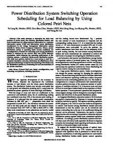
following the MPP of the micro hydro power station, designed with an optimum duty cycle perturbation step in accordance with the turbine-generator group dynamics. As can be noted, all the active power generated by the MHPP (shown in blue dashed lines) is injected into the electric grid, except losses, with small delays in the dynamic response. It can be also seen the case with fixed voltage control of the rectified voltage Vd, i.e. with no MPPT control (T0 at all times) and consequently with near constant rotor speed operation (shown in green dotted lines). In this case, the power injected into the electric grid is much lesser than with MPPT, about an average 30 % lower. Eventually, no reactive power is exchanged with the electric grid since VCM is not activated (shown in red solid lines). Simulations of Fig. 6 show the case with active and reactive power exchange with the utility grid, i.e. the APCM is activated all the time while the VCM is activated at t=0.6 s. As can be seen, all the active power generated by the MHPP is injected into the electric grid, except losses, in the same way than the case with only APCM activated. The rapid injection of almost 300 var of reactive capacitive power into the electric system (shown in red solid lines) when the VCM is activated aims at increasing the PCC voltage from 0.99 p.u. up to 1 p.u. (shown in the last figure). This reactive power generation increases the VSI losses, which causes a slightly lower exchange of active power than the previous case studied with both controls of the Z-source inverter (with and without MPPT). V. CONCLUSION In this paper, a novel power conditioning system and control strategy of a three-phase grid-connected MHPP, incorporating a MPPT for dynamic active power generation jointly with reactive power compensation of distribution systems, has been presented. Simulation studies and experimental results demonstrate the effectiveness of the proposed detailed models and control approaches in dq reference frame. The fast response of power electronic devices and the enhanced performance of
Fig. 6. Simulation results for active and reactive power exchange (APCM and VCM).
the control allow taking full advantage of the MHPP as a distributed generator. REFERENCES [1]
H.L. Willis and W.G. Scott, Distributed Power Generation – Planning and Evaluation. 1st ed. Marcel Dekker, 2000. [2] S. Rahman, “Going green: the growth of renewable energy,” IEEE Power & Energy Magazine, vol. 1, no. 6, pp. 16-18, Nov./Dec. 2003. [3] A, Date and A. Akbarzadeh, “Design and cost analysis of low head simple reaction hydro turbine for remote area power supply,” Renewable Energy vol. 34, no. 2, pp. 409-15, 2009. [4] H. Fang, L. Chen, N. Dlakavu and Z. Shen, “Basic modeling and simulation tool for analysis of hydraulic transients in hydroelectric power plants,” IEEE Trans. on Energy Conv., vol. 23, no. 3, pp. 834-41, 2008. [5] A. Ansel and B. Robyns, “Modelling and simulation of an autonomous variable speed micro hydropower station,” Mathematics and Computers in Simulation, vol. 71, no. 4, pp. 320-32, June 2006. [6] J.M. Carrasco, L. Garcia-Franquelo, J.T. Bialasiewicz, E. Galván, R.C. Portillo, M.A. Martín, J.I. León and N. Moreno, “Power electronic systems for the grid integration of renewable energy sources: A survey,” IEEE Trans. on Ind. Electronics, vol. 53, no. 4, pp. 1002-16, 2006. [7] J.L. Márquez, M.G. Molina and J.M. Pacas, “Modeling and Simulation of Hydraulic Microturbines for Applications in Distributed Generation,” in HYFUSEN 2009, 2º Iberian-American Congress on Hydrogen and Sustainable Energy Sources, San Juan, Argentina, July 2009, p. 1-8. [8] F.Z. Peng, “Z-Source Inverter,” IEEE Transactions on Industry Applications, vol. 39, no. 2, pp. 504-510, March/April 2003. [9] P.C. Loh, D.M. Vilathgamuwa, Y.S. Lai, G.T. Chua, and Y. Li, "Pulsewidth modulation of Z-source inverters," IEEE Trans. Power Electronic, vol. 20, pp. 1346-55, 2005. [10] M.G. Molina, D.H. Pontoriero and P.E. Mercado. “An efficient MPPT controller for grid-connected photovoltaic energy conversion system”. Brazilian Journal of Power Electronics, vol. 12, no. 2, pp. 147-54, 2007. [11] M.G. Molina and P.E. Mercado, “Control of tie-line power flow of microgrid including wind generation by DSTATCOM-SMES Controller,” in IEEE ECCE 2009, Energy Conversion Congress and Exposition, September 2009. p. 2014-21. [12] The MathWorks Inc., “SimPowerSystems for use with Simulink: User’s Guide”, R2009a, Sept. 2009. Available at: .
1738