Scale Dilation/Erosion. A. Gasteratos, I. Andreadis and Ph. Tsalides. Laboratory of Electronics. Section of Electronics and Information Systems Technology.
Improvement of the Majority Gate Algorithm for Grey Scale Dilation/Erosion A. Gasteratos, I. Andreadis and Ph. Tsalides Laboratory of Electronics Section of Electronics and Information Systems Technology Department of Electrical and Computer Engineering Democritus University of Thrace Xanthi 67100, Greece
Indexing Terms: Mathematical morphology, Computer vision.
An improvement of the majority gate algorithm suitable for grey scale morphological operations is presented in this letter. The redundancy of temporal signals led to a simplified hardware implementation. It is shown that max/min operators can be computed by the same circuit. A new pipelined systolic array architecture based on this circuit is illustrated for dilation/erosion operations.
Introduction: Mathematical morphology offers a unified and powerful approach to numerous image processing problems, such as shape extraction, noise cleaning and object selection according to their size distribution [1]. The two most basic morphological operations are dilation and erosion. Grey scale dilation is defined as the maximum of the sums of the image window pixels and the corresponding structuring element pixels [2]. Similarly grey scale erosion is the minimum of the differences. Morphological image processing machines, such as the cytocomputer and the CLIP array processors have been built [3]. Speed can be significantly improved by using the threshold decomposition technique, but hardware cost becomes prohibitively expensive as the resolution of the image increases [4]. Recently, a new algorithm based on the majority gate median filtering algorithm [5] has been proposed in [6]. This is basically a bit-sliced algorithm where the different bits of each addition/subtraction result is processed by different processing elements (PEs). Also, the max/min computation is achieved by different PEs.
An improvement of the majority gate algorithm suitable for grey scale morphological operations has been proposed in this letter. The redundancy of temporal signals led to a simplified hardware implementation of the PE. Additionally, it has been shown that there is no need for different PEs to calculate max/min operators. Both operators can be computed by the same PE. This circuit combined with an adder/subtractor circuit can implement the operations of dilation and erosion. As dilation and erosion usually operate on the image in sequence it becomes clear that in order to implement any other morphological operation, there is no need to perform them simultaneously.
The extension of the majority-gate algorithm: In order to describe the proposed algorithm the notations and the definitions found in [6] have been adopted. Let y be the output signal of the max/min operator and n the window
2
size of the operator. Then, the operator has n inputs bi . Also, oj is the j th bit of the binary representation of y.
It has been shown that [6] : oj =(t 1,j ) OR (t 2,j ) OR ... OR (t n,j )
for the max operator and
(1) oj =(t 1,j ) AND (t 2,j ) AND ... AND (t n,j )
for the min operator
(2) where t i,j is a temporal signal defined as: t i,j =(f i,j ) AND (bi,j )
for the max operator and
(3) t i,j =(f i,j ) OR (bi,j )
for the min operator
(4)
and f i,j is the flag signal indicating whether bi remains within the set of the maxima or the minima : f i,j +1 =(f i,j ) AND [(t i,j ) XNOR (oj )]
for the max operator and
(5) f i,j +1 =(f i,j ) OR [(t i,j ) XOR (oj )]
for the min operator
(6)
The following improvements have been made to previous briefly described technique. By substituting (3) into (5) and using Boolean algebra : f i,j+1 =(f i,j ) AND {[(f i,j ) AND (bi,j )] XNOR (oj )} =(f i,j ) AND {[(fi ,j ) OR (bi ,j )] AND (oj ) OR [(f i,j ) AND (bi,j ) AND (oj )]} =(f i,j ) AND {[(bi ,j ) AND (oj )] OR [(bi,j ) AND (oj )]} =(f i,j ) AND [(bi,j ) XNOR (oj )]
for the max operator
(7)
Similarly it can be shown that : f i,j+1 =(f i,j ) OR [(bi,j ) XOR (oj )] (8)
3
for the min operator
Furthermore, substituting (3) into (1) : oj =[(b1,j ) AND (f 1,j )] OR [(b2,j ) AND (f 2,j )] OR ... OR [(bn,j ) AND (f n,j )] (9)
Also, eqn (7) can be rewritten as follows : f i,j=(f i,j -1 ) AND [(bi,j -1 ) XNOR (oj-1 )] (10)
and by substituting (10) into (9) : oj =[(b1,j ) AND {(f 1,j -1 ) AND [(b1,j -1 ) XNOR (o0 )]}] OR [(b2,j ) AND {(f 2,j -1 ) AND [(b2,j -1 ) XNOR (o1 )]}] OR ... OR [(bn,j ) AND {(f n,j -1 ) AND [(bn,j -1 ) XNOR (on-1 )]}] (11)
Similarly, using eqns (2), (4) and (8) it can be shown that : oj =[(b1,j ) OR {(f 1,j -1 ) OR [(b1,j -1 ) XOR (o0 )]}] AND [(b2,j ) OR {(f 2,j -1 ) OR [(b2,j -1 ) XOR (o1 )]}] AND... AND [(bn,j ) OR {(f n,j -1 ) OR [(bn,j -1 ) XOR (on-1 )]}] (12)
and through De Morgan's law eqn (12) becomes : oj =[(b1,j ) AND {(f 1,j -1 ) AND [(b1,j -1 ) XNOR (o0 )]}] OR [(b2,j ) AND {(f 2,j -1 ) AND [(b2,j -1 ) XNOR (o1 )]}] OR ... OR [(bn,j ) AND {(f n,j -1 ) AND [(bn,j -1 ) XNOR (on-1 )]}] (13)
From (7) and (11) it is clear that coefficients t i,j are not needed for the computation of f i,j+1 and, therefore, a hardware simplification has been achieved compared to that proposed in [6]. Also, eqns (11) and (13) show that there is no
4
need for realisation of different circuits in order to compute the max and the min operators. More specifically, the max operator circuit can be implemented using eqn (11), whereas the min operation circuit can be implemented by the same circuit, by simply inverting both the inputs and the outputs. As an illustration, suppose that the minimum of n binary numbers is required. If these numbers are complemented bit by bit, then the minimum becomes maximum and it can be traced by a max operator circuit. By inverting the previous result the minimum is obtained.
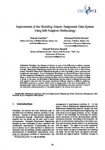
Figure 1 shows the implementation of the PE based on eqn (13). This is capable of processing 3x3 image windows data. In order to compute the min values, bi,j and bi,j
-1
invert f i,j
are inverted by means of XNOR gates. However, there is no need to +1 ,
since they are obtained from the aforementioned PE. This can be
seen by applying De Morgan's law on eqn (8) and comparing the result with eqn (7). The initial conditions are: f i,1 ="1", b0 ="1", o0 = "1" and f i,1 ="0", b0 ="0", o0 = "0" for the max/min operations, respectively. Figure 2 depicts a pipelined systolic array capable of computing grey-scale dilation and erosion of 8 bit resolution images, using the PEs of Figure 1. Of course, the architecture is scalable to handle images of higher resolution.
Conclusions: An improvement of the majority gate algorithm suitable for grey scale morphological operations has been proposed in this letter. The redundancy of temporal signals led to a simplified hardware implementation. Also, it has been shown that max and min operators can be computed by the same PE. A pipelined systolic array architecture based on this PE has been illustrated, for both dilation and erosion operations.
References
5
1
HARALICK, R. M., STERNBERG, S. R. and ZHUANG, X., 'Image
analysis using mathematical morphology' IEEE Trans. Pattern Analysis and Machine Intelligence, 1987, 9, (4), pp. 532-550. 2
STERNBERG, S. R., 'Grayscale morphology' Computer Vision
Graphics and Image Processing, 1986, 45, pp. 333-355. 3
DUFF, M. J. B. and FOUNTAIN, T. J., 'Cellular logic image processing',
(Academic Press, London, 1986). 4
ANDREADIS, I., GASTERATOS, A. and TSALIDES, Ph., 'An ASIC
for fast grey-scale dilation', to appear in Microprocessors and Microsystems. 5
LEE, C. L. and JEN, C. W., 'Bit-sliced median filter design based on
majority gate', IEE Proc. G, 1992, 139, 1, pp. 63-71. 6
CHEN, C. H. and YANG, D. L., 'Realisation of morphological operations'
IEE Proc.-Circuits Devices Syst., 1995, 142, 6, pp. 364-368.
6
FIGURE CAPTIONS
Figure 1. Max/min PE operator for a 3x3 image window data. Figure 2. A pipelined systolic array for computing dilation and erosion of 8-bit resolution images.
7
o j -1 min/max bj-1
fj -1
bj
bj bj -1
oj fj
fj -1 f j
Figure 1
8
p1
s1
R
s9
R
R
. . .
. . .
. . .
A/S
R
R
.
.
R
. . .
R .
.
.
R
b1 ...
R
A/S : Adder/Subtractor R
.
R . . .
p9
A/S
b0 f0 o0
b8 ... f1
PE
R
.
.
.
R
.
.
.
R
o1
: Register
y
: Output
pi
: Image pixel
si
: Structuring element pixel
PE
: Processing Element (shown in Figure 1)
Figure 2
9
PE o8
R
b9 ...
o9 R
y