Index Terms - coordinate, digital signature, Elliptic. Curve Cryptosystem, iris, message digest, pixel. 1 Introduction. Biometric recognition has become a common ...
International Journal of Computer Science and Information Security (IJCSIS), Vol. 14, No. 5, May 2016
Improving Authentication of an Iris Recognition System by Digital Signature via Elliptic Curve Cryptosystem K.Spurthy Computer Science & Engineering KL University, AP, INDIA
T.N.Shankar Computer Science & Engineering KL University, AP, INDIA
Abstract- Iris recognition is used since quite some time for identification for various purposes and with various interfaces like PC logon, access control mechanisms, and tracking of offenders from the scene of crime. Iris edged over other means of authentication performance in terms of cost benefit, device size, and its convenience of use. Many issues still remain unresolved with the use of iris authentication process. We suggest the use of Digital signature through Elliptic Curve Cryptosystem (ECC) that is embedded with the iris which can provide enhanced authentication and security.
Index Terms - coordinate, digital signature, Elliptic Curve Cryptosystem, iris, message digest, pixel 1 Introduction Biometric recognition has become a common and reliable way to authenticate the identity of a living person based on physiological or behavioural characteristics. Physiological features such as fingerprint[5], iris pattern, and facial feature are having relatively stable physical characteristics. A behavioural characteristics is more a reflection of an individual’s psychological makeup as signature, speech pattern, or how one strikes a key stroke at a keyboard. The degree of intra-personal variation in a physical characteristic pattern is smaller than that of a behavioural pattern. For example, a signature is influenced by both controllable actions and less psychological factors, and speech pattern is influenced by current emotional state, whereas iris template is independent of these physiological parameters.
135
Ranjan K.Senapati Electronics & Communication Engineering , KL University, AP
Nevertheless all physiology based biometrics don’t offer satisfactory recognition rates (false acceptance and/or false reject rates, respectively referenced as FAR and FRR). The automated personal identity authentication systems based on iris recognition are considered to be the most reliable among all biometric methods. The probability of finding two people with identical iris pattern is almost zero. That’s why iris recognition technology is becoming an important biometric solution for people identification employing access control mechanism as networked access to computer application. Iris is protected from the external environment behind the cornea and the eyelid. The process of aging has virtually no effect and the small-scale radial features of the iris remain stable and almost fixed over the entire span of one's life. For all of these reasons, iris patterns become interesting as an alternative approach for reliable visual recognition of individuals when recognition process can be employed at a distance of less than a meter, and especially when there is a need to search very large databases without incurring any false matches despite a huge number of possibilities. Although small (11 mm) and sometimes problematic to image, the iris has the great mathematical advantage that its pattern variability among different persons is enormous. In the following sections, there is a brief discussion on Iris anatomy in section 2, Digital signal through ECC in section 3, development of hashing algorithm in section 4, section 5 performance analysis, security analysis in section 6, security strength in section 7 and section 8 concludes the paper.
https://sites.google.com/site/ijcsis/ ISSN 1947-5500
International Journal of Computer Science and Information Security (IJCSIS), Vol. 14, No. 5, May 2016
2 Iris Anatomy Iris biometric system is the most suitable system to meet all current battlefield requirements because the unique features of the iris. The iris has many features that can be used to distinguish one iris from another. One of the “primary visible characteristic feature is the trabecular meshwork, a tissue which gives the appearance of dividing the iris in a radial fashion” for that is permanently formed by the time of eighth month of gestation. During the development of the iris, there is no genetic influence on it, a process known as “chaotic morphogenesis” that occurs during the seventh month of gestation, which means that even identical twins have differing irises. The iris has in excess of “266 degrees of freedom”, i.e. the number of variations in the iris that allow one iris to be distinguished from another. The fact that the iris is protected behind the eyelid, cornea and aqueous humour means that, unlike other biometrics such as fingerprints, the likelihood of damage and/or abrasion is minimal. The iris is also not subject to the effects of aging which means it remains in a stable form from about the age of one until death. The use of glasses or contact lenses (coloured or clear) has little effect on the representation of the iris and hence does not interfere with the recognition technology. 2.1 Iris Template Generation Iris template generation includes inner and outer boundary localization, removing the noise generated by eyelashes, remapping of iris and generating the template.The boundaries can be located by using Daugman’s integro differential operator [2] i.e
max
( r , x0 , y0 )
G (r ) r
r , x0 , y0
I ( x, y ) ds 2 r
By using this formula the boundary can be searched in the entire scope of the eye image. To have an efficient method of improving time over the Daugman’s algorithm, which include coarse stage and fine stage to locate the boundary within the iris scope [3]. This reduces the searching time. Two steps are involved in the localization of boundaries 1. Coarse stage – finding center and radius of boundaries 2. Fine stage – locating the exact boundary
136
2.1.1 Inner Boundary Localization (Pupil Boundary) Coarse Stage:
Fig.1(a) The original image
Fig.1(b) Binary image
Fig.1(c) Morphological operation Fig.1(d) Detect lower contour of pupil and its boundary Figure 1(a) The original eye image (b) Binary image of the Figure 1(a) (c) Figure after morphological operation with the Figure 1(b) (d) Detection of lower contour of the pupil and its boundary of the Figure 1(c) After the binary operation the iris image, morphological open operation is adopted to reduce the noise and occlusion. The lower contour, denoted as γ, is computed on the resulted binary image. For the nth column, γ (j) is the Y-coordinate of the last black pixel. If there is no black pixel in this column, γ (j) = 0. The thick real line in Figure 1(d) shows the lower contour in Figure 1(c). Besides the exact lower contour of the pupil, the obtained γ may contain some noises introduced by eyelashes and eyelid. Thus, it is required to find out the part of the pupil on γ and use it to estimate the parameters of the inner boundary (denoted as xp, yp and rp). The detailed process can be described as follows: The lower contour denoted as γ, and for jth column, γ(j) is the y-coordinate of the last black pixel. If there is no black pixel in this column then γ(j) = 0.
https://sites.google.com/site/ijcsis/ ISSN 1947-5500
International Journal of Computer Science and Information Security (IJCSIS), Vol. 14, No. 5, May 2016
Algorithm 1 Following are the steps to find the pupil’s radius and center Step 1. Find the nonzero zone corresponding to the pupil on γ ( AD in Figure 1(d)).
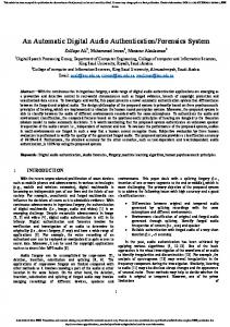
Fig. 2(a) Eye
Step 2. Find the maximum of γ in this zone. Denote this point as Q and its value as yQ. Step 3. Compute the gradient of γ. And find the nearest extremum points of the gradient on both sides of Q . ( BC in Figure 1(d)).
Figure 2(a) is a figure of eye. Figure 2(b) depicted the Iris boundary by using the Daugman formula. 2.1.3 Finding and Removing Upper and Lower eyelid Boundaries The iris center should be considered as pupil center because they are nearly concentric circles i.e (xs, ys) as (xp, yp). Hence it needs to find only rs (radius of iris) which will be obtained by considering the average intensity signals on both right and left side of pupil.
Step 4. Estimate xp, yp, rp by i. . ii. rp
Fig. 2(b) Iris localization boundary
BC 2
Consider the right side average signal as SR and for each pixel (i,j) satisfying xp+1.2rp