Journal of Materials Science & Technology 32 (2016) 1372–1377
Contents lists available at ScienceDirect
Journal of Materials Science & Technology j o u r n a l h o m e p a g e : w w w. j m s t . o r g
Improving Joint Features and Mechanical Properties of Pinless Fiction Stir Welding of Alcald 2A12-T4 Aluminum Alloy Zhenlei Liu 1,2,*, Hutao Cui 1, Shude Ji 2,*, Minqiang Xu 1, Xiangchen Meng 2 1 2
Harbin Institute of Technology, Deep Space Exploration Research Center, Harbin 150080, China Faculty of Aerospace Engineering, Shenyang Aerospace University, Shenyang 110136, China
A R T I C L E
I N F O
Article history: Received 27 April 2016 Received in revised form 19 May 2016 Available online 4 July 2016 Key words: Pinless friction stir welding Groove distribution 2A12-T4 aluminum alloy Macrostructures Mechanical property
As a new solid state welding, pinless friction stir welding (PFSW) can be used to join thin-wall structures. In this study, four new pinless tools with different groove distributions were designed and manufactured in order to enrich technological storage of PFSW and obtain sound joint with high quality of alclad 2A12-T4 alloy. The results show that the small-obliquity tool is detrimental to the transfer of plasticized materials, resulting in the formation of kissing bond defect. For the through-groove tool or the large-curvature tool, bigger flashes form on the joint surface and alclad layer is observed in the nugget zone (NZ), deteriorating mechanical properties. Compared with the above-mentioned three tools, using the six-groove tool with rational curvature and obliquity can not only yield sound joint with small flashes and thickness reduction, but also prevent alclad from flowing into NZ, which has potential to weld thin alclad aluminum alloys. Meanwhile, the tensile strength and elongation of joint using the six-groove tool reach the maximum values of 362 MPa and 8.3%, up to 85.1% and 64% of BM. Copyright © 2016, The editorial office of Journal of Materials Science & Technology. Published by Elsevier Limited.
1. Introduction As one of high-strength aluminum alloys (Al–Cu–Mg alloy), 2A12 aluminum alloy owns the benefits of good corrosion resistance and high fracture toughness, and has been widely used in aerospace, automobile and transportation and so on[1,2]. However, because of high thermal conductivity and thermal expansion coefficient, solidification crack defects always appear in the joint when using traditional fusion welding technique. Especially for the thin-wall construction, the higher peak temperature in fusion welding is not only detrimental to the formation of joint, but also results in big residual stress and distortion, which always restrict the wide application of thin-wall construction of 2A12 aluminum alloy. Friction stir welding (FSW) is a solid state welding, which can effectively circumvent the disadvantages associated with fusion welding. For instance, to date, the criterion to select optimal process parameters has been well developed for FSW aluminum alloys[1,2]. Moreover, the size effect and anisotropy of friction stir welded sheets have also been revealed[3,4], which is extremely useful to optimize the design of a welded structure. However, pinless friction stir welding (PFSW) is a new solid state welding technique derived from traditional FSW, whose related research remains scarce. Li et al.[5]
* Corresponding authors. Fax: +86 24 89723479. E-mail addresses:
[email protected] (Z. Liu);
[email protected] (S. Ji).
performed experiment of 1.5 mm thick 2024-T3 aluminum alloy using involute grooves shoulder tool and found that lazy S could be eliminated under optimum welding parameters. Moreover, Li et al.[6] also used the involute groove tool to eliminate hook defect formed in the friction stir spot welding. Tozaki et al.[7] employed pinless tool with scroll groove on shoulder and successfully obtained sound spot welding joint of 6061 aluminum alloy. In fact, geometry on the shoulder plays a significant role on the transfer of material. Bakavos et al.[8] expounded that material flow was decided by geometry of shoulder, which controlled the penetration of the plastic zone into the bottom sheet. Therefore, how to design the geometry of shoulder has become a hotspot about PFSW process. Zhang et al.[9] respectively designed three kinds of shoulders with inner-concave groove, concentric-circles groove and threespiral groove, and found that the shoulder with three-spiral groove could better transfer the plasticized materials, which was the best choice to weld the thin plate of 2024 alloy. In addition, shoulder diameter also affects mechanical properties of joint. Forcellese and Simoncini[10] employed two plane shoulders with 8 mm and 19 mm in diameters to perform PFSW of AZ31 magnesium alloy and found that the mechanical property of joint increased with increasing shoulder diameter. According to the above-mentioned, it can be inferred that rational design of groove plays an important role on the joint quality of PFSW. Up to the present, effect of groove distribution on joint quality is still seldom reported. Therefore, in our pre-experiment,
http://dx.doi.org/10.1016/j.jmst.2016.07.003 1005-0302/Copyright © 2016, The editorial office of Journal of Materials Science & Technology. Published by Elsevier Limited.
Z. Liu et al. / Journal of Materials Science & Technology 32 (2016) 1372–1377
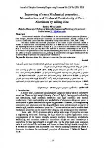
in order to enrich technological storage of PFSW, four pinless tools with large-curvature, small-obliquity, six-groove and throughgroove were designed and manufactured, and the 6061-O aluminum alloy was chosen as research object[11]. As a matter of fact, for 2000 or 7000 series alloy plate, in order to obtain good corrosion resistance, alclad layer is produced on the surface of the plate. However, during traditional FSW process, the alclad layer easily flows into the weld because of the stirring action of pin and then deteriorates mechanical properties. Therefore, in order to prevent the alclad layer from flowing into weld and then to obtain high quality joint, the four kinds of pinless tools were employed to weld thin-wall construction of 2A12 alloy. Meanwhile, effects of shoulder geometry on surface formation, macrostructure, distribution of alclad layer and mechanical properties of PFSW joint were mainly investigated in details. 2. Experimental Procedure The base material (BM) used in this study was 0.87 mm thick alclad 2A12-T4 aluminum alloy plate, whose tensile strength and elongation were 425 MPa and 13%, respectively. These pinless tools employed in this experiment are made of H13 steel tool and own six curving grooves. The close-up photographs of four pinless tools are shown in Fig. 1. These pinless tools have also been used to weld 6061-O aluminum alloy[9]. In this study, the pinless tool in Fig. 1(a) is called the six-groove tool. According to the characteristics of groove geometry and distribution different from the six-groove tool, the other three pinless tools are respectively named the large-curvature tool (Fig. 1(b)), the small-obliquity tool (Fig. 1(c)) and the throughgroove tool (Fig. 1(d)). Moreover, the shoulder diameter, groove width and depth are 10 mm, 1 mm and 0.5 mm, respectively. The lengths of grooves of the large-curvature tool, the small-obliquity tool, the six-groove tool and the through-groove tool are approximately 4 mm, 5 mm, 5 mm and 6 mm. The curvature radii of grooves of the largecurvature tool, the small-obliquity tool, the six-groove tool and the through-groove tool are about 7 mm, 8.4 mm, 8 mm and 8 mm. In this study, the pinless tool rotates clockwise in order to make much more materials flow into the groove, which has been validated in our pre-experiment. In order to better compare effects of groove distribution on surface formation and macrostructure of PFSW joints, the welding speed of 500 mm/min and rotational velocity of 900 rpm were constant. All the PFSW experiments were carried out using FSW-3LM-4012 machine, while the butt joint was produced. The tilt angle in contrast to Z-axis was chosen as 1.0°. Moreover, in order to reduce distortion of the thin-wall construction, the workpieces to be welded were clamped using a titanium alloy plate which was 1 mm away from the edge of the shoulder. In addition, all the plates to be welded were polished by emery paper and cleaned using acetone to wipe off oxide layer and oil contamination. After PFSW, macrostructural and mechanical specimens were cut perpendicular to the welding direction using an electrical discharge machine. The macrostructural features were etched using Keller’s reagent (2 mL HF, 3 mL HCl, 5 mL HNO3 and 190 mL H2O)
1373
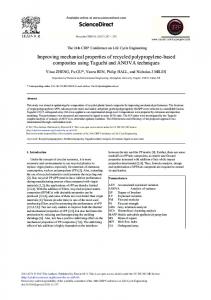
and observed by an optical microscope (OLYMPUS, GX71). Three tensile specimens were cut and tested in order to evaluate effect of groove distribution on mechanical property of PFSW joint with reference to ISO 4136[12], while average value was prepared for discussion. The crosshead speed in the tensile test was 3 mm/min using a universal tensile machine (Landmark MTS). Moreover, hardness of PFSW joint was measured at the load of 200 g for 10 s and the interval between two adjacent points was 1 mm. 3. Results and Discussion 3.1. Surface formation of joint Surface formation of joints employing four kinds of pinless tools are exhibited in Fig. 2. It is observed that arc corrugation and flash defects resulted from the rotation of shoulder appearing on the surfaces of all joints, which are also the typical characteristics of a traditional FSW joint[13]. However, sizes and shapes of the flashes on the surface of joints are very different. It is observed from Fig. 2(a) that sound joint with small flashes can be attained using the sixgroove tool. As a matter of fact, when the pinless tool rotates clockwise, with the rotation and advancement of pinless tool, the plasticized materials continuously flow into the groove. The materials in the groove always undergo two main forces: positive pressure caused by the side wall of the groove and friction force by the wall of the groove[11]. It can be deduced that the resultant between positive pressure and friction force is beneficial to drive plasticized materials in the groove flowing toward the end of the groove. With the advancement of pinless tool, more materials flow into the groove and then accumulate at the end of the groove. Under large vertical forge force provided by the machine, materials that accumulated at the end of the groove easily flow toward the bottom according to the law of minimum resistance. Consequently, the materials in the bottom also flow toward the top and toward the edge of the shoulder. For the large-curvature tool, larger flashes appear on the surface of the joint, as exhibited in Fig. 2(b). This is because the larger curvature is detrimental to make material flow into the groove and then transfer material from the shoulder edge to the shoulder center. As indicated in Fig. 2(c), because the end of groove of the small-obliquity tool is far away from the center of the shoulder, plasticized material is difficult to transfer effectively, forming bigger flashes. Compared with the six-groove tool, the groove in Fig. 1(d) is through. When the through-groove tool is used, big flashes form on the two sides of the joint (Fig. 2(d)), whose mechanism of formation is different from those of the small-obliquity tool and the large-curvature tool. During PFSW by the through-groove tool, much more materials flow into the groove and then accumulate. However, the through groove has difficulty preventing materials from overflowing, obtaining bigger flashes. In addition, this phenomenon is different from PFSW of 6061-O using the through-groove tool in which flashes also appear on the middle of the joint[11]. This may be because 2A12 alloy has high flow stress, which makes its flow difficult during the PFSW process.
Fig. 1. Four kinds of pinless tools used in this experiment: (a) the six-groove tool, (b) the large-curvature tool, (c) the small-obliquity tool, (d) the through-groove tool.
1374
Z. Liu et al. / Journal of Materials Science & Technology 32 (2016) 1372–1377
Fig. 2. Surface formation of joints using different pinless tools: (a) the six-groove tool, (b) the large-curvature tool, (c) the small-obliquity tool, (d) the through-groove tool.
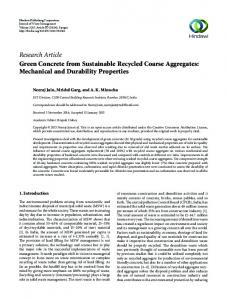
3.2. Macrostructures Fig. 3 shows macrostructures of joints using four pinless tools with different shoulder shapes. It is observed that when using the six-groove tool, the large-curvature tool and the through-groove tool, the sound joint can be attained. During the PFSW process, the materials are heated by the friction between shoulder and workpieces, and then flow under the actions of groove on the shoulder surface. Therefore, the rational shoulder shape is beneficial to improve the disappearance of original interface between two workpieces, joining the two workpieces. Moreover, compared with Fig. 3(b–d), it is seen that thickness reduction phenomenon is small because of smaller flashes using the six-groove tool. Larger flashes appear on the surface of joints using the other three pinless tools and then lead to the
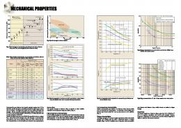
bigger thickness reduction compared with the six-groove tool. In fact, thickness reduction always results in the decrease of the area of loading bearing, and then deteriorates mechanical properties of the joint. Therefore, it can be deduced that the six-groove tool may be propitious to the increase of mechanical properties. In fact, for traditional FSW, the tool pin may result in the appearance of cavity or tunnel defect when material flow is insufficient. For PFSW in this study, pinless tool can effectively avoid the appearance of cavity or tunnel defect. However, kissing bond becomes the most important defect influencing the quality of welding joint. It is found in Fig. 3(c) that the small-obliquity tool has difficulty obtaining defectfree joint and then causes the kissing bond defect to form at the bottom of the joint, as shown in Fig. 4, which is an enlarged picture marked by the red square in Fig. 3(c). During FSW process, joint
Fig. 3. Macrostructures of joints using different pinless tools: (a) the six-groove tool, (b) the large-curvature tool, (c) the small-obliquity tool and (d) the through-groove tool.
Z. Liu et al. / Journal of Materials Science & Technology 32 (2016) 1372–1377
Fig. 4. Enlarged pictures of kissing bond defect marked by red square in Fig. 3(c).
quality is related to frictional heat and material flow behavior. For the PFSW in this study, material flow behavior is driven by the groove on the surface of the shoulder. With the rotation and advancement of pinless tool, the plasticized material flows into the inlet and then flows out of the outlet of the groove. The materials near the shoulder on the surface of the joint experience higher frictional heat and then own good material flow behavior. The materials suffer from heat input from thermal conduction, easily resulting in insufficient material flow and then forming kissing bond defects. In addition, frictional heat input increases by increasing the distance away from the shoulder center, resulting in the lowest flow stress
1375
of material under the shoulder edge and bigger flow stress in the center of the shoulder. For the small-obliquity tool, the end of the groove is far away from the shoulder center, making it difficult for the material to flow into the center of the shoulder according to the law of minimum resistance. The above-mentioned reasons lead to the occurrence of kissing bond in PFSW joint by the small-obliquity tool. Similar to traditional FSW[13], the PFSW joint is also divided into four zones: NZ, thermo-mechanically affected zone (TMAZ), heat affected zone (HAZ) and BM, as exhibited in Fig. 5. It is observed that BM is composed of lath shape grains owing to the rolling process (Fig. 5(a)), while HAZ consists of coarse grains induced by high thermal cycle and no mechanical stirring effect, as shown in Fig. 5(b). Meanwhile, because the material experiences mechanical stirring and thermal cycle, TMAZ is featured by elongated, deformed and bended grains, as revealed in Fig. 5(c, d). Moreover, it is worth mentioning that TMAZ on the AS (Fig. 5(c)) is clearer than that on the RS (Fig. 5(d)). This is because that material in AS undergoes bigger shear stress and higher peak temperature compared with that in RS, which is beneficial to improve plastic deformation of material in AS and then to obtain clear boundary[14]. Observing Fig. 5(e), the NZ is characterized by fine and equiaxed grains resulting from the occurrence of dynamic recrystallization caused by higher heat input and bigger strain rates[13–16]. Moreover, it is clearly observed that white bands appear in the NZ of the joint, especially for the largecurvature tool and the through-groove tool. In fact, the white bands have been validated by References [17, 18], which are the alclad layers. The Schematic of material flow of alclad layer using the
Fig. 5. Microstructures in different positions of typical joint using the six-groove tool: (a) BM, (b) HAZ, (c) interface between NZ and TMAZ on the AS, (d) interface between NZ and TMAZ on the RS and (e) NZ.
Z. Liu et al. / Journal of Materials Science & Technology 32 (2016) 1372–1377
1376
Fig. 6. Schematic of material flow of alclad layer when using the through-groove tool.
through-groove tool is indicated in Fig. 6. During PFSW process, when the large-curvature tool or the through-groove tool is employed, the bigger flashes appear on the two sides of the joint surface, which results in the loss of plasticized material and then forms instantaneous cavity inside the joint. Therefore, the alclad layer in the bottom easily flows upward and mixes with 2A12 alloy. For the sixgroove tool, because very small flashes form, much material in the weld is surrounded by the shoulder and the hard materials near the weld, and no big instantaneous cavity appears, making it difficult for the alclad layer in the bottom to flow upward. As mentioned above, the small-obliquity tool is detrimental to obtain better material flow, which causes difficulty of the plasticized material to be transferred in the bottom. In fact, the alclad layer is pure Al, whose hardness is far less than that of 2A12 alloy. Therefore, the alclad layer may result in the decrease of mechanical property. Compared with 6061-O alloy[11], the 2A12 alloy owns alclad layer in order to corrosion resistance. However, if the big alclad appears in the NZ of joint, this is detrimental to mechanical property. Therefore, compared with the other three pinless tools (the large-curvature tool, the small-obliquity tool and the through-groove tool), the sixgroove tool can prevent alclad into NZ and then improve mechanical property, which has significant advantages to weld the other alclad Al alloys. 3.3. Microhardness Fig. 7 indicates the hardness distributions of joints by four different pinless tools. It is seen that hardness distribution of PFSW joint presents a typical W shape. The hardness of NZ is lower than BM, but higher than HAZ and TMAZ. As a matter of fact, 2A12
Fig. 7. Hardness distribution of joints using four kinds of pinless tools.
Fig. 8. Tensile properties of joints using four kinds of pinless tools.
aluminum alloy belongs to precipitate strengthening alloy[1,2]. During PFSW process, higher frictional heat easily results in the coarsening, dissolution and reprecipitation of strengthening phases, and then causes that hardness value of NZ to become lower than BM[19–21], which is different from PFSW of 6061 alloy[11]. Moreover, the materials in the HAZ only experience high thermal cycle, which easily obtains coarser grains and then reduces hardness value. For the TMAZ, the materials experience frictional heat and mechanical stirring effect, which is propitious to the increase of dislocation density and then improves hardness. In the above-mentioned, the NZ featured by fine and equiaxed grains is beneficial to the increase of hardness according to the Hall–Petch formula in which the finer the grains, the higher the hardness[22]. Therefore, the hardness value of NZ is higher than values in the HAZ and TMAZ. It is also observed that the hardness value of NZ using the six-groove tool is higher than those using the other three tools, which may result from low peak temperature. In addition, the hardness of typical position with white bands in Fig. 3 was measured and the hardness value is about 18 HV, which can be considered as pure aluminum. 3.4. Tensile properties of joint Mechanical properties of joints using different pinless tools are shown in Fig. 8. It can be seen that groove distribution plays a significant influence on mechanical properties. When using the sixgroove tool, the tensile strength and elongation of joint reach the maximum values of 362 MPa and 8.3%, which are equivalent to 85.1% and 64% of BM. Meanwhile, the small-obliquity tool obtains the lowest values of 157 MPa and 0.8% compared with the other three pinless tools. In this study, mechanical properties of joint are influenced by many factors such as location of defect, hardness, thickness reduction and distribution of alclad layer. According to the above-mentioned results, the sound joint with smaller thickness reduction and no alclad layer in the NZ is obtained using the six-groove tool, which is beneficial to the increase of mechanical property. For the small-obliquity tool, the lowest mechanical property is attributed to kissing bond defect formed in the bottom of the joint. Although no welding defects appear in the joints using the large-curvature tool and the through-groove tool, alclad layer in the NZ easily leads to stress concentration, while thickness reduction induced by big flashes is bigger, whose combined effect may reduce mechanical properties. Moreover, Yan et al.[19] also expounded that the alclad layer in the NZ of fusion welding joint was detrimental to mechanical property, because it can be considered as inclusion inside weld. The fracture location of joint using the
Z. Liu et al. / Journal of Materials Science & Technology 32 (2016) 1372–1377
1377
in the bottom of the PFSW joint, resulting in the lowest tensile properties. (3) The most appropriate pinless tool is the six-groove tool, which can achieve the better transfer of plasticized material. Defectfree joint with smaller thickness reduction and flashes can be attained. Importantly, the six-groove tool can prevent the alclad layer from flowing into the NZ. Therefore, the maximum values of tensile strength and elongation of joint using the six-groove tool are 362 MPa and 8.3%, up to 85.1% and 64% of BM. Acknowledgments
Fig. 9. Fracture locations of tensile specimens by four kinds of pinless tools: (a) the six-groove tool, (b) the large-curvature tool, (c) the small-obliquity tool, (d) the through-groove tool.
This work is supported by the National Natural Science Foundation of China (No. 51204111), the Natural Science Foundation of Liaoning Province (No. 2014024008) and the Aeronautical Science Foundation of China (No. 2014ZE54021). References
six-groove tool is located in the NZ (Fig. 9(a)). For the largecurvature tool and the through-groove tool, the bigger flashes appear on the surface of the joint (Fig. 2(b, d) and the much alclad layers mix with 2A12 alloy (Fig. 3(b, d)), which easily leads to fracture in the NZ. Observing Fig. 9(b, d), the joints fracture in the NZ. Moreover, under tensile stress, the kissing bond appears at the bottom of the joint by the small-obliquity tool and then easily propagates. As shown in Fig. 9(c), it can be seen that the fracture location of the joint lies in the NZ of the joint under the small-obliquity tool. 4. Conclusions In order to prevent alclad layer from flowing into NZ and to broaden the application of thin plates of 2A12-T4 alloy, four kinds of pinless tools (the six-groove tool, the large-curvature tool, the small-obliquity tool and the through-groove tool) were designed and manufactured, while butt experiments of 2A12-T4 aluminum alloy were performed. Based on the present investigation, the following conclusions can be extracted. (1) The PFSW joint can be divided into four zones: BM, HAZ, TMAZ and NZ. The alclad layer appears in the NZ because of bigger flashes when using the large-curvature tool and the through tool, which is detrimental to mechanical property. (2) Because the end of the small-obliquity groove is far away from the center of the shoulder, the kissing-bond defect appears
[1] A. Arora, T. DebRoy, H.K.D.H. Bhadeshia, Acta Mater. 59 (2011) 2020–2028. [2] Z.H. Zhang, W.Y. Li, J.F. Li, Y.J. Chao, Int. J. Adv. Manuf. Technol. 73 (2014) 1213–1218. [3] Z.H. Zhang, W.Y. Li, Y. Feng, J.L. Li, Y.J. Chao, Acta Mater. 92 (2015) 117–125. [4] Z.H. Zhang, W.Y. Li, F.F. Wang, J.L. Li, Mater. Lett. 162 (2016) 94–96. [5] W.Y. Li, J.F. Li, Z.H. Zhang, D.L. Gao, W.B. Wang, G.H. Luan, Trans. Tianjin Univ. 20 (2014) 439–443. [6] W.Y. Li, J.F. Li, Z.H. Zhang, D.L. Gao, W.B. Wang, C.L. Dong, Mater. Des. 62 (2014) 247–254. [7] Y. Tozaki, Y. Uematsu, K. Tokaji, J. Mater. Process. Technol. 210 (2010) 844–851. [8] D. Bakavos, Y.C. Chen, L. Babout, P. Prangnell, Metall. Mater. Trans. A 42 (2011) 1266–1282. [9] L.G. Zhang, S.D. Ji, G.H. Luan, C.L. Dong, L. Fu, J. Mater. Sci. Technol. 27 (2011) 647–652. [10] A. Forcellese, M. Simoncini, Mater. Des. 36 (2012) 123–129. [11] S.D. Ji, X.C. Meng, L. Ma, S.S. Gao, Int. J. Adv. Manuf. Technol. (2016) doi:10.1007/ s00170-016-8734-x. [12] ISO 4136, Destructive Tests on Welds in Metallic Materials-Transverse Tensile Test, Geneva: International Organization for Standardization, 2001. [13] R.S. Mishra, Z.Y. Ma, Mater. Sci. Eng. R. 50 (2005) 1–78. [14] D.X. Li, X.Q. Yang, L. Cui, F.Z. He, H. Shen, Mater. Des. 64 (2014) 251–260. [15] J.Q. Li, H.J. Liu, J. Mater. Sci. Technol. 31 (2015) 375–383. [16] Y.X. Huang, B. Han, S.X. Lv, J.C. Feng, H.J. Liu, J.S. Leng, Y. Li, Sci. Technol. Weld. Joi. 17 (2012) 225–230. [17] W.F. Xu, J.H. Liu, D.L. Chen, J. Mater. Sci. Technol. 31 (2015) 953–961. [18] X.C. Meng, Z.W. Li, L. Ma, S.S. Gao, J. Mater. Eng. Perform. 25 (2016) 1228–1236. [19] K. Yan, Z.X. Ma, J. Zhang, J. Mater. Eng. Perform. 9 (2008) 44–47. [20] Z.W. Li, S.D. Ji, Y.N. Ma, P. Chai, Y.M. Yue, S.S. Gao, Int. J. Adv. Manuf. Technol. (2016) doi:10.1007/s00170-015-8276-7. [21] L. Wan, Y.X. Huang, W.Q. Guo, S.X. Lv, J.C. Feng, J. Mater. Sci. Technol. 30 (2014) 1243–1250. [22] K.S. Arora, S. Pandey, M. Schaper, R. Kumar, J. Mater. Sci. Technol. 26 (2010) 747–753.