in its routes. We evaluate ILTP and its integration with CTP on three large-scale testbeds, namely: Motelab [15], Twist [20], and. Indriya [22] and show that ILTP is ...
1
Improving Link Quality by Exploiting Channel Diversity in Wireless Sensor Networks Manjunath Doddavenkatappa, Mun Choon Chan and Ben Leong School of Computing, National University of Singapore Email:{doddaven,chanmc,benleong}@comp.nus.edu.sg
Abstract—A large percentage of links in low-power wireless sensor networks are of intermediate quality. To the best of our knowledge, opportunistic exploitation is currently the only way to use these links. However, such exploitation requires overhearing which consumes a significant amount of energy. In this paper, we propose a new approach to exploit intermediate quality (IQ) links through channel diversity with a new protocol, called IQ Link Transformation Protocol (ILTP), that does not require overhearing. ILTP transforms IQ links into good links thus allowing us to exploit such links continuously rather than using them only opportunistically. Our key insight is that the packet reception ratios (PRR) across different channels on IQ links are not correlated and it is common on such links to find channels that change in quality on the time scale of a few minutes. Consequently, when the link quality of a channel is bad, it is highly likely that a good channel can be found and its quality will remain good for at least a few minutes. Our evaluations on three large-scale testbeds demonstrate that ILTP is able to consistently transform the IQ links into good links. We observe that even a poor link with a PRR of 0.05 can be transformed into a good link with a PRR greater than 0.9. When ILTP is integrated with CTP, the default collection tree protocol for TinyOS, the average number of transmissions per end-to-end packet delivery is reduced by 24% to 58%.
I. I NTRODUCTION Existing routing protocols attempt to choose only good quality links to build their routes [5] and such links often have packet reception ratio (PRR) greater than 0.9. However, typically a large proportion of about one-third of the links in practical sensor networks have their PRR in the range from 0.1 to 0.9 [5], [32], [33]. The ratio is higher than 50% for earlier Mica devices [10]. These links are commonly referred to as intermediate quality (IQ) links and they are typically not used for routing [5]. While IQ links are deemed too unstable by existing routing metrics, such links typically have longer range than good quality links. There is a potential for significant energy savings if these IQ links can be used for routing. In fact, some approaches to exploit such links to improve routing performance have been proposed [26], [5]. However, these approaches require nearby nodes to perform overhearing even if they are not the intended recipients. Such overhearing consumes a significant amount of energy, thus limiting the achievable gain. In this paper, we propose a novel technique called IQ Link Transformation Protocol (ILTP) to exploit IQ links without overhearing. ILTP effectively transforms IQ links into good quality links (with PRR > 0.9) by exploiting channel diversity.
It allows routing protocols to reduce the number of hops in their routes (and thus transmissions) by allowing them to use transformed long-range IQ links. As IQ links are typically exploited only for bulk transport [26], [5], we design ILTP specifically to serve bulk data. ILTP can be used to support several categories of sensor network applications such as structural health monitoring [14], [27], [17], event-driven applications like active volcano monitoring [19], sensor networks deployed for gathering data for scientific study [3], [6], [7], and surveillance systems [28]. However, we also show that ILTP can be used to support periodic traffic over a duty-cycling MAC. ILTP is based on two key observations that we found in our measurement studies. First, there is very little correlation in the quality of an IQ link across different ZigBee channels. In more than 80% of the cases, the correlation coefficient for the link quality between any two channels on the same IQ link is either negative or below 0.1. Second, it is common to find sufficient number of channels for an IQ link, that change in quality on the time scale of a few minutes, so that the underlying IQ link can be transformed into a good link by switching among such channels once every few minutes. However, channel quality varies over time and depends on the location of the node. This means that it is not feasible to pre-define channel switchings in advance. ILTP transforms the quality of IQ links by addressing two key questions: first, how can we identify a channel with good quality efficiently? Second, how can we synchronize channel switching between 2 nodes of a link when channels are consistently changing and packets are being lost? In ILTP, we use a probing phase to eliminate poor channels so that we can switch to a good channel with high probability and our requirement is only local synchronization for which we use a data-driven mechanism based on a shared random seed. ILTP is able to transform a typical IQ link into a good link by switching an average of 15.1 channels per link per hour. We demonstrate the utility of ILTP by integrating it with CTP [4], the default collection tree protocol for TinyOS. ILTP allows the collection protocol to exploit long-range IQ links without requiring the overhearing of transmissions, thus reducing energy consumption by reducing the number of hops in its routes. We evaluate ILTP and its integration with CTP on three large-scale testbeds, namely: Motelab [15], Twist [20], and Indriya [22] and show that ILTP is able to consistently transform IQ links into good links. We observe that even a
2
poor link with PRR 0.05 can be transformed into a good link with PRR greater than 0.9. With ILTP integrated, the average number of transmissions per end-to-end packet delivery for CTP routes is reduced by 24% to 58%. The following are our contributions: (1) We observe that when the link quality of a channel on an IQ link is bad, it is easy to find another channel where the link quality is good and it stays good typically for a few minutes. This is because we have found that empirically, the PRR across different channels on IQ links are not correlated and sufficient number of channels on such links tend to change in quality on the time scale of a few minutes. Our measurements show that whenever the PRR of a link falls below 0.7, there is a 85% chance that there exists at least one other channel with a PRR value ≥ 0.7. (2) We propose ILTP, a protocol that allows to exploit IQ links without overhearing. ILTP also allows us to use such links constantly rather than exploit them only opportunistically by transforming an IQ link on a single channel into a good link by switching among different channels. Moreover, we demonstrate these utilities of ILTP by integrating it with CTP. (3) We present a complete implementation of ILTP and its integration with CTP in TinyOS-2.1.1. We evaluate its performance on three large-scale testbeds with results showing a significant reduction in the number of transmissions. The rest of the paper is organized as follows. We discuss related work in Section II. Section III presents our link measurements and trace-based emulation of transformation of IQ links using channel diversity. We present ILTP in Section IV together with the details of its implementation. The integration of ILTP with CTP is discussed in Section V. Section VI presents the evaluation results on different testbeds. Finally, we conclude in Section VII. II. R ELATED W ORK To the best of our knowledge, Sanjit and Morris were the first to attempt to exploit intermediate quality links in wireless (WiFi) networks with opportunistic routing (ExOR) [26] by exploiting their long-range to improve throughput. ExOR is not a feasible solution in low-power wireless sensor networks since it requires overhearing, which consumes a significant amount of energy. Furthermore, ExOR also requires coordination among receivers which adds to the overall overhead. Links of intermediate quality in low-power sensor networks have been studied extensively by Srinivasan et al. [8]. They proposed a metric called the 𝛽-factor to quantify the correlation among consecutive packet losses or successful transmissions on such links. They found that more than 85% of IQ links have a value of 𝛽 above 0.8 with their link quality correlated over time spans of a few hundred milliseconds. To exploit the observed correlation, Srinivasan et al. propose an algorithm called opportune transmissions, which pause for an interval immediately after a transmission failure. In contrast, our aim is to transform IQ links into good links so that transmissions can proceed. Furthermore, opportune
transmissions is designed to avoid bursty losses for good links that routing protocols use in building their routes [5], [8], and not for IQ links that are typically ignored. Alizai et al. were the first to attempt to exploit low-power IQ links that are ignored by current routing protocols with a technique called Bursty Routing Extensions (BRE) [5]. Because transmission successes are correlated on IQ links [8], the key idea of BRE is for nodes to volunteer to forward packets if they overhear the consecutive transmissions of their neighbors on IQ links and have lower ETX values to the destination than the default route. This approach can reduce the number of transmissions because IQ links tend to have longer range. The key drawback of BRE is that it requires overhearing. It makes an assumption that all nodes in the network are awake while a bulk of data is served, which is typically not the case for practical sensor networks [13]. Waking-up and forcing duty-cycling neighbors to engage in overhearing can consume significantly higher energy than the savings that can be achieved by a reduction in the number of transmissions. Even in object detection and tracking applications [28], it is not required for the entire network to switch from duty-cycling to basic contention mode when an object is detected. Moreover, typically in-network aggregation is used in such applications that in turn limits the number of nodes that need to be awake and be involved in the reporting of an event. There exists a plethora of protocols that exploit channel diversity available in sensor networks [30], [11], [12], [16]. Most of these efforts attempt to achieve parallel transmissions so as to increase the capacity of the network. On the other hand, we use channel diversity to exploit long-range IQ links. Channel diversity has also been used to improve the stability of links [23], [24], [25]. Like opportune transmissions [8], these works also attempt to improve long-term stability of the good links that routing protocols use in their routes. To the best of our knowledge, our concept of using channel diversity to exploit long-range IQ links that are currently ignored by routing protocols without having to overhear transmissions is novel. III. M OTIVATION FOR E XPLOITING C HANNEL D IVERSITY In this section, we provide an overview of the IEEE 802.15.4 MAC/PHY specification (ZigBee) standard, and show with a trace-based measurement study that there is much potential for transforming IQ links into good links by exploiting channel diversity in a practical sensor network. A. Background ZigBee is currently the de facto standard for wireless sensor networks (WSNs). It supports 16 non-overlapping channels (usually referred by numbers 11 through 26) and these channels are defined in the 2.4 GHz ISM band with each channel occupying a bandwidth of 2 MHz and an inter-channel separation of 3 MHz. Although non-overlapping, a channel is not orthogonal to all the other channels. Concurrent transmissions on adjacent channels will result in interference [16]. The channels can however be divided into two sets of orthogonal
3
B. Collection of Traces In order to understand whether we can always find a good channel when the link quality of the currently used channel degrades, we conducted experiments to investigate how the link quality of ZigBee channels varies over time. To this end, we used an experimental setup consisting of 16 TelosB motes, divided into two sets of 8 senders and 8 receivers. The motes in the each set are placed adjacent to one another in a row to minimize spatial differences. The distance between the set of senders and the set of receivers is adjusted so that PRR on the TinyOS default channel (26) is of intermediate quality. The default PRR values on our experimental IQ links range from 0.02 to 0.75. All the eight senders start transmission at the same time but each on a different channel and a sender continuously transmits packets to its associated receiver at an inter-packet interval (IPI) of 15 milliseconds. Because each pair of a sender and a receiver is set to communicate on a different orthogonal channel, their transmissions should not interfere. The successful transmissions and packet losses are recorded over a duration of one hour. We repeat this experiment at 7 different physical locations and on both sets of orthogonal channels. The locations include two research labs, an apartment, a soccer field, a running track, and two building corridors. The analysis presented is based on the 14 (7 × 2) sets of traces with each set spanning 1 hour and containing parallel transmissions on 8 orthogonal channels. C. Correlation among Different Channels We first look at how PRR varies among the different channels. We compute the Pearson’s correlation coefficient of the PRRs among different channels at different levels of granularity, from a single packet (15 milliseconds) to 66 packets (1 second). Across all granularities, channel sets, and locations, we observe that the correlation coefficients for distinct pairs of IQ channels are either negative or close to a
TABLE I C ORRELATION COEFFICIENT MATRIX OF PRR OBSERVED ON AN IQ LINK . Ch 11 13 15 17 19 21 23 25
11 1.0 -.09 -.09 .03 .15 -.32 -.06 .07
13 -.09 1.0 -.16 .10 -.16 -.03 .00 -.10
15 -.09 -.16 1.0 -.37 .00 .11 -.37 .25
17 .03 .10 -.37 1.0 .13 .08 .10 -.10
19 .15 -.16 -0.0 .13 1.0 -.01 -.02 .10
21 -.32 -.03 .11 .08 -.01 1.0 .16 -.12
23 -.06 .00 -.37 .10 -.02 .16 1.0 -.27
25 .07 -.10 .25 -.10 .10 -.12 -.27 1.0
PRR .33 .19 .63 .46 .81 .81 .41 .28
value of 0.1 in most cases. For example, an average of 83.7% of channel pairs per link are observed to have such coefficient values at the granularity of single packet. As an illustration, Table I depicts a correlation coefficient matrix observed on an IQ link in a research lab. The last column of the table lists observed PRR values for individual channels. The depicted coefficients are computed using samples of PRR values over a moving window of size 200 milliseconds (13 packets). We found that about 89% of the channel pairs have coefficients that are either negative or close to 0.1. There are even pairs of channels which are weakly negatively correlated. 1 0.9 0.8 0.7 0.6 PRR
channels, with each containing 8 channels — (11, 13, ⋅ ⋅ ⋅ , 25) and (12, 14, ⋅ ⋅ ⋅ , 26). Moreover, all 16 channels interfere with WiFi channels. However, the channels 15, 20, 25, and 26 do not interfere with the three commonly used WiFi channels 1, 6, and 11 [2]. Consequently, channel 26 is typically used as the default ZigBee channel. While the first generation WSN radio transceivers such as CC1000 take around 50 milliseconds to switch between two channels [31], the switching cost has been dramatically reduced in modern transceivers. The widely used CC2420 transceiver and the more recent CC2500 have channel switching times of only 300 microseconds and 90 microseconds respectively [21]. Such an overhead is negligible when compared to the 4 milliseconds required to transmit a maximumsized packet (of 128 bytes). Moreover, if contention backoff overheads are included, the typical time for the transmission of a data packet and the reception of the corresponding acknowledgment is about 15 milliseconds. Therefore, the overhead of channel switching, which can be expected to reduce further in the future, is negligible even on a per-packet basis.
0.5 0.4 0.3 0.2 0.1 0
20 24 26 5
10
15
20
25 30 35 time (minutes)
40
45
50
55
60
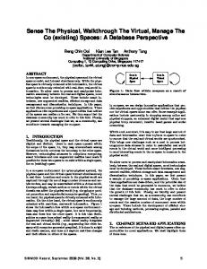
Fig. 1. Plot of PRR over a duration of one hour for different channels on an IQ link.
D. Rate of Fluctuation of Channel Quality From our traces, we observe that different channels on different IQ links fluctuate in quality on a time scale of a few minutes. As an illustration, we plot the PRR of 3 different channels on an IQ link over a total duration of one hour in Fig. 1. We see that when a channel enters the good phase (where PRR > 0.9), it tends to stay there for a few minutes. In addition, at any given point of time, it is highly likely that at least one channel is operating in the good phase. Therefore, in this particular trace, we find that the underlying IQ link can be transformed into a good link of PRR 0.96 with an overhead of only 4 channel switches (i.e. 26 → 20 → 24 → 20 → 26), including the initial switch from the default channel 26.
4
1 0.9 0.8 0.7 0.6 0.5 0.4 0.3 0.2 0.1 0
optimal random
0
60 120 180 240 channel duration (seconds)
300
CCDF
(a) Distribution of channel durations 1 0.9 0.8 0.7 0.6 0.5 0.4 0.3 0.2 0.1 0 0 1 2 3 4 5 6 7 number of channels with PRR >= CST
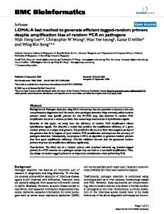
(b) Distribution of the number of channels staying above CST Fig. 2.
Observations during emulation of transformation of IQ links.
Avg. PRR per link
1
0.9
0.8
0.7
1s 5s 10s 0.1 0.2 0.3 0.4 0.5 0.6 0.7 0.8 0.9 CST
1
(a) PRR against CST 500
# channel switchings
Our trace analysis suggests that when the quality of one channel is bad, the quality of the other channels can be very different and hence there is a possibility that a better channel can be found. Moreover, we also observed that the quality of such channels fluctuate on a time scale of a few minutes. So, the first question is if a channel degrades in quality, how easy is it to find a good channel? Next, how often does such probing for a good channel needs to be performed? To answer these questions, we perform a trace-driven emulation based on our 14 sets of packet traces. We divide each trace into intervals called PRR Windows (PRRWND), and the PRR for each window is the proportion of successful transmissions in the window. Starting with a given channel, we traverse the packet trace one window at a time. We switch to a new channel only if the PRR for the current window is less than a pre-defined threshold which we call the Channel Switching Threshold (CST). This process emulates a simple channel selection scheme that switches among different channels depending on the instantaneous measured PRR. We emulate two different approaches for selecting a new destination channel when a channel switch is performed. In the first approach, which we refer to as optimal, we choose the channel that has PRR above CST for the longest duration after the switch. Clearly, such an approach is not practical, but it does provide us with a useful lower bound on the minimum number of channel switches required to keep the link quality high. In the second approach, we simply select a channel at random from the set of available channels. We were able to achieve an average transformed PRR of above 0.9 per link for both optimal and random selection strategies. The lowest PRR observed on the transformed links is 0.8 and it is observed for the case of using the random selection strategy on one of the links where the quality of channels changed rapidly. After every channel switch, we also record time spent in the destination channel before switching to another channel. The utility of a channel switching is determined by the duration for which the quality of the new channel remains good after the switch. If frequent switches are required, our approach would not work well. We plot the CCDF (Complementary Cumulative Distribution Function) of such channel durations observed for both optimal and random cases in Fig. 2(a). For the optimal case, we observe that 48% of the channel durations last for more than one minute. This allows to transform an IQ link into a good link using an average of only 10 channel switches per hour. For random channel selection, only 14% of the channel durations are longer than one minute and it takes on average 39 channel switches per hour to keep the link quality high. The gap between the optimal and random curves can be explained with Fig. 2(b), where we plot the CCDF of the number of channels available with PRR ≥ CST when a channel switch is to be performed using the random selection strategy. We find that the probability of having more than 3 such channels (out of the 7 available channels) is about only 0.2. This means that the random strategy selects a bad channel frequently.
CCDF
E. How Easy is it to Find a Good Channel?
400
1s 5s 10s
300 200 100 0 0.1 0.2 0.3 0.4 0.5 0.6 0.7 0.8 0.9 CST
1
(b) Number of channel switches against CST Fig. 3.
Choice of values for CST and PRRWND.
In all our evaluations, we set the channel switching threshold to 0.7 and PRRWND to 5 seconds. We explain the choice of these parameters with Figs. 3(a) and 3(b), which plot the average transformed PRR and the number of channel switchings respectively, observed at different values of the channel switching threshold for different window sizes for the random selection strategy. It is clear that our chosen values trade off the achieved quality for the number of channel switches. Basically, if we switch too aggressively, we end up with a large number of channel switches; if we do not switch aggressively enough, the overall link quality achieved drops. While we consider the orthogonal sets separately in our
5
0.5
PRR
0.4 0.3 0.2 0.1 0 0
500 1000 1500 2000 time (switching number)
2500
(a) Channel 11 0.6 0.5
PRR
0.4
links without the need for overhearing transmissions so that duty-cycling nodes that are not part of the active path need not be awakened. We design our transformation algorithm called the IQ Link Transformation Protocol (ILTP) specifically to serve bulk data and it is based on the above-discussed observations. However, as we will demonstrate in our experiments, ILTP can also be used to support periodic traffic over a duty-cycling MAC. To implement ILTP, we address two key issues: (i) how to select a good channel efficiently; and (ii) how to coordinate the switching of channels between the sender and the receiver of an IQ link to be transformed. In the rest of this section, we discuss how ILTP deals with these two issues and describe some pertinent details of its implementation.
0.3 0.2
A. An Efficient Channel Selection Strategy
0.1
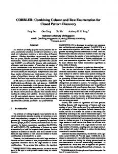
We noticed in our experimental locations and practical sensor testbeds that among the 16 ZigBee channels on IQ links, there are often a few channels that have poor reception for long durations in the order of a few hours or even for a few days. We performed a simple experiment to validate this observation. We picked an IQ link on the Indriya testbed [22] and recorded the PRR of different channels for the link over a 5-hour period, by switching to a random channel every second and transmitting packets with an inter-packet interval of 15 milliseconds. Channel switching is coordinated using the wired control channel provided by the testbed. We plot the PRR of two poor channels (11 and 21) in Fig. 4. As shown, most of the data points lie well-below 0.1 with a considerable number of them concentrating on the x-axis close to the PRR of 0. While we observed intermediate PRR values ranging from 0.43 to 0.65 on other channels, the PRR of the poor channels 11 and 21 over the 5-hour experiment was only 0.01 and 0.06 respectively. The first step in our channel selection strategy is to identify and remove these poor channels. This improves the probability that ILTP will find a good channel when it needs to do channel switching as the link quality on these poor channels tend to remain poor over extended periods of time. After such poor channels are eliminated, ILTP will select a channel at random from the remaining working set of available channels whenever the PRR of the current channel falls below the channel switching threshold (CST). Since we are working with IQ links, there is a tendency for the quality of these links to fluctuate between good and bad states. The channels that we want to use are those which tend to stay in the good state for a few minutes. Channels that change rapidly in the order of a few milliseconds to a few hundred milliseconds are classified as the transient channels and removed from the working set. They are only used if there are no more available channels in the working set. 1) Identifying Poor Channels: Poor channels can either be pre-filtered or they can be detected on-the-fly during link transformation. If we probe all the channels and filter out the poor channels in advance, there is more message overhead at the beginning, but we can avoid the additional latency
0 0
500 1000 1500 2000 time (switching number)
2500
(a) Channel 21 Fig. 4. Behavior of poor channels over a long duration of 5 hours on an IQ link in Indriya testbed.
analysis, it is reasonable to consider all 16 channels at the same time in practice. However, the inclusion of more channels will only be useful if bad channels are excluded so that the probability of selecting a good channel remains high. The design of ILTP takes these issues into consideration. IV. IQ L INK T RANSFORMATION P ROTOCOL (ILTP) Typically, IQ links are exploited for bulk transport [26], [5]. There are several categories of sensor network applications which transfer data in bulk such as structural health monitoring [14], [27], [17], event-driven applications like active volcano monitoring [19], and sensor networks deployed for gathering data for scientific study [3], [6], [7] can also benefit from transferring gathered data in bulk. For these applications, it is desirable to download data sequentially from each of the nodes with only one flow from a source node to the sink being active at a time [13], [9], [14], [19]. This is because such sequential download allows us to achieve ultra-low power consumption [13]. Moreover, accommodating multiple parallel flows is not worth the required efforts [1]. In addition, these applications do not have real-time requirements. Two key observations in these applications motivate our work. First, when a flow is active, only the nodes on the path from the source to the sink of the flow would be awake with rest of the network continuing in duty-cycling [13]. This saves a significant amount of energy. Second, bulk data is typically collected over long routes made up of high-quality links (hops) [13], [14] as it is expensive to handle disruptions during bulk transfers. We aim to shorten such long paths by exploiting long-range IQ links but ensuring the same highquality through transformation. Moreover, we exploit such IQ
6
Algorithm 1: Channel Selection Algorithm Given: working set (𝐺) Initialize states: transient set (𝑇 =∅) For every PRRWND measure PRR If PRR < CST If PRR < 0.3 // verify for transiency insert current channel into 𝑇 If (𝐺 ∕= ∅) and (∃𝑐 ∈ 𝐺 ∣ 𝑐 ∕= current channel) change current channel to a random channel in 𝐺 Else dequeue all channels in 𝑇 and insert them into 𝐺 change current channel to a random channel in 𝐺
arising from switching into the poor channels during actual data transmissions for on-the-fly identification. We will show in our evaluations in Section VI-D that either method will work in practice. We choose the pre-filtering approach for ILTP to trade off better latency for slightly higher overhead at the start. However, as the PRR of poor channels remain poor for long periods, pre-filtering does not need to be performed on every attempt to transform an IQ link. In practice, the system may need to run this filtering step only when a significant change in the environment is detected or periodically, perhaps once every few hours or even days. For pre-filtering, we transmit packets over a duration of 5 seconds with an inter-packet interval of 250 milliseconds for each of the 16 channels. The somewhat long duration of 5 seconds helps to reduce the likelihood of marking rapidly changing transient channels as poor channels. Based on the observed PRR, we remove channels with PRR ≤ 0.1 from the working set. In our evaluations, an average of 4 channels on each link are eliminated in this step, leaving only 12 channels in the working set, for the three testbeds that we worked with. 2) Channel Selection: Once the poor channels are identified and excluded, the nodes start by selecting a random channel in the working set (𝐺). The PRR of the channel is assessed at a constant rate in windows of size PRRWND and actions are taken according to Algorithm 1. A channel switching occurs whenever the PRR of the current channel falls below the CST. If the PRR is below the transient channel threshold 0.3, the current channel is added to the transient set (𝑇 ). We pick a threshold of 0.3 because transient channels change rapidly in the order of a few milliseconds to a few hundred milliseconds, and over a PRRWND of 5 seconds, this translates to a measured PRR that is lower than 0.3. The channels that remain in the good state for minutes could possibly also be added to the transient set during their bad phases. Hence, if the working set becomes empty, we will move all the channels in the transient set to the working set and restart Algorithm 1. B. Coordinating Channel Switching As the sender and the receiver of an IQ link to be transformed have to perform the channel switches dynamically
depending on the environment and in the presence of packet losses, coordination is necessary. We adopt a data-driven approach and use actual data packets to coordinate the two nodes. As ILTP switches channels based on the measured bidirectional PRR, the challenge is to ensure that receiver is able to infer that the bi-directional PRR has dropped below the channel switching threshold particularly when there are losses of the acknowledgement packets from the receiver. Our coordination/synchronization scheme is as follows: 1) While the new channel is selected at random, the sender and receiver share a common random seed, so that both will decide to switch to the same channel. It is worth noting that a random seed is exchanged every time before starting transformation and the requirement is only local not global synchronization. As explained in Section V, ILTP ensures that the receiver of an IQ link that is being transformed would not receive traffic from any node other than the sender on that IQ link. Therefore, all that is needed is the local synchronization between only the sender and the receiver of the link. 2) Packet transmissions are regular and rate-controlled. This allows the receiver to synchronize its clock to that of the sender on the reception of every packet. As packets are rate-controlled with an inter-packet interval of a few packet transmission times, clock drift is not an issue. The use of rate control serves another important function that it enables the receiver to know when a packet is expected and is therefore able to infer a packet loss based on timing. The rate-limiting of transmissions do not pose a problem. This is because typically WSN protocols already rate-limit transmissions in order to avoid selfinterference. For example, CTP uses an average interval of 2 packet transmission times between completion of a transmission and start of the next transmission [4], [8]. However, in practice, the interference range can be more than two hops and an interval of up to 4 packet times may be necessary [14]. As the same interval can also be exploited by ILTP, rate-limiting imposes no penalty. 3) We embed one byte of PRR information in each packet transmitted to indicate the number of successful transmissions seen so far in the current PRRWND at the sender. This allows the receiver to accurately infer the bi-directional PRR perceived at the sender. 4) While random seed, rate control, and embedded PRR information together allows the receiver to coordinate channel switching with the sender, a timeout mechanism is still required so that if the sender and receiver lose synchronization due to a large number of consecutive packets loss, the link can be declared unusable. The overhead required to coordinate a sender and a receiver includes the following: (1) a handshaking SYN packet and its acknowledgment; (2) piggybacking one byte of the number of transmission successes in every packet; and (3) a few control messages transmitted to notify the receiver to exclude poor and transient channels and to handle a possible coordination error. These overhead are negligible compared to the number of
7
Sender
Receiver
V. I NTEGRATION OF ILTP WITH CTP
SYN SYN−ACK
initiation identification of poor channels
data−ack exchanges on all 16 channels convey list of poor channels if any
data−ack exchanges over PRRWND
verification: transient channel ?
Y convey transient channel number
N
PRR < CST ? Y
change channel
Fig. 5.
N
N
PRR < CST ? Y
change channel
Operation of ILTP.
transmissions reduced by ILTP. We observe in our experiments that, on average, only 0.18% of the total transmissions are control packets. C. Implementation The implementation of ILTP is depicted in Fig. 5. The sender node of an IQ link initiates the protocol on the default channel by transmitting a SYN packet. On receiving a SYN, the receiver acknowledges the SYN and updates its state variables along with starting its timers. Once synchronized, the sender starts transmitting data packets and enters the initiation phase during which it identifies and filters the poor channels. At the end of the initiation phase, the list of poor channels is communicated to the receiver in a control packet. The sender then proceeds with data transmissions with verifying and switching channels as described earlier in Algorithm 1. For evaluation, we implemented ILTP in TinyOS-2.1.1 as a separate layer between the routing and MAC layers. To make ILTP modular and to make link transformation transparent to the routing layer, ILTP is implemented as two separate components: the sender and the receiver. The sender component is responsible for handling transmissions of both control and data packets, while their reception is handled by the receiver component. The sender component provides an AMSend1 interface to the routing layer for submitting its packets. The submitted packets are processed and then handed over to the underlying AM stack using another AMSend. Similarly, the receiver component uses and provides Receive interfaces to respectively receive packets from the AM stack and signal their reception to the routing layer. Moreover, these components also provide and use interfaces for communicating routing control packets such as beacons on the default channel. 1 The networking component of TinyOS is often referred to as Active Message (AM) stack as reception of its packet triggers an action at the receiver. The component provides AMSend and AMReceive interfaces as APIs in order to send and receive radio messages.
In order to evaluate the utility of ILTP, we integrate it with CTP [4], the default TinyOS collection tree protocol. We choose CTP as it chooses long routes made up of highquality links [5], which are similar to the stable routes assumed by bulk transfer applications. In addition, the availability of a stable implementation and its popularity also make it an attractive choice. While ILTP is implemented at a layer below the routing, ILTP cannot be oblivious of CTP because ILTP has to identify and transform IQ links. In order to identify IQ links, ILTP accesses CTP’s neighbor table maintained by its 4-bit link estimator [18]. A sender will decide to transform one of its IQ links if the receiver on that link has lower ETX by at least a value of 1.0 compared to the ETX of its default parent chosen by CTP2 . This is depicted in Fig. 6, where node 7 identifies its IQ link to node 5 which has an ETX value that is lower than the ETX of its default parent node 6 by 1.0. Links represented by solid lines are of ETX 1.0. A similar ETX difference threshold is also used in [5] by an overhearing node to identify such progress. However, in our case, as it is a sender that identifies such progress and because the chosen IQ link is transformed and exploited continuously, the need for overhearing is completely eliminated. If there are more than one IQ link which offer better progress than the default parent, we choose the one that provides the maximum progress. As depicted in Fig. 6, node 4 chooses to transform its IQ link to node 1 instead of the IQ link to node 3. This is because node 1 provides better progress as it has an ETX of 1.0 while node 3 has an ETX of 2.0. Moreover, node 4 chooses node 1 as its new parent. It is worth noting that this decision does not affect the stability of the collection tree as we transform IQ links to exploit them continuously instead of using them only opportunistically. Root 0
5
1
2
6
7
Fig. 6.
3
4 IQ Link Link with ETX 1.0 (CTP route)
Routing progress offered by IQ links.
Once a receiver is supporting transformation of an incoming IQ link, it is not allowed to forward traffic from any node other than the sender on that link. By not allowing receivers of transformed links to forward traffic from other nodes, we reduce the complexity of the CTP+ILTP protocol significantly. Note that this is not a problem for practical bulk data applications 2 In evaluations, we set this difference threshold to 1.5. This ensures that links that ILTP selects for transformation are indeed of intermediate quality as CTP’s threshold for parent switching is also 1.5.
8
because such data is collected sequentially from each of the nodes with only one flow being active at any time [13], [9], [14], [19]. Moreover, because a large proportion of nodes in typical collection trees are leaf nodes and thus do not have to forward traffic for other nodes, this restriction is typically not a major concern even for sparse traffic. As illustrated in Fig. 6, node 4 transforms its IQ link to the leaf node 1 while ignoring its IQ link to the non-leaf node 2 although both the nodes offer the same progress. We show in Table II the proportion of leaf nodes observed on CTP trees in three testbeds when the trees are built with a randomly selected root at both the maximum and minimum transmit power levels, at which the network remains connected. More than 50% of the nodes are leaves in all cases at both the transmit power levels. A maximum of 73 leaf nodes of the total 86 nodes can be observed at 0 dBm for the dense deployment of the Twist testbed. TABLE II P ERCENTAGE OF LEAF NODES ON CTP TREES IN DIFFERENT TESTBEDS . Testbed Motelab Motelab Twist Twist Indriya Indriya
Power (dBm) 0 -10 0 -25 0 -15
Total no. of nodes 94 94 86 86 125 125
No. of leaf nodes 51 56 73 51 81 67
% of leaf nodes 54% 60% 85% 59% 65% 54%
VI. E VALUATION In this section, we evaluate ILTP and its integration with CTP on three large-scale testbeds, namely Motelab [15], Twist [20], and Indriya [22]. Motelab is deployed at the Harvard University and it has TmoteSky devices. Twist is also composed of TmoteSky devices and it is deployed at the Berlin Institute of Technology (TU Berlin). Indriya is a testbed facility of TelosB motes deployed by the National University of Singapore. The nodes in all these testbeds span three floors of a building. Moreover, due to the difficulties involved in maintaining large-scale testbeds, the number of active nodes in these testbeds varies over time. During our experiments, about 85, 90, and 125 nodes were available on Motelab, Twist, and Indriya respectively. A. Experimental Methodology We evaluate ILTP and its integration with CTP (CTP+ILTP) separately. Each data point for our experiments corresponds to a duration of 30 minutes. Moreover, experiments corresponding to any two data points compared are carried out back to back in time so that temporal differences can be minimized. However, this may be violated at times because the testbeds used are shared resources. We use the maximum transmit power level of 0 dBm on Motelab and Indriya and lower power levels of -15 and -7 dBm on Twist since the Twist testbed is much denser. For all experiments, unless specified otherwise, the inter-packet interval as regulated by ILTP is 250 milliseconds.
All the presented results corresponding to ILTP and CTP+ILTP include the control overhead required for achieving and maintaining synchronization in channel switching. Furthermore, the PRR metric used is bi-directional and accounts for the loss of acknowledgment packets. In the figures, we use the terms ML, TL, and IL to refer to links on Motelab, Twist and Indriya respectively. Similarly, we use the terms MR, TR, and IR to refer to routes on these testbeds. B. Transformation of IQ Links into Good Links using ILTP To evaluate the performance of ILTP in transforming IQ links into good links, we transform 15 IQ links with five links from each of the three testbeds. In Fig. 7, we plot three PRR values for each of the 15 IQ links: (i) the intermediate quality PRR observed on the default channel 26, (ii) the transformed PRR for ILTP that includes the initiation overhead that identifies and eliminates poor channels (denoted by WILTP), and (iii) the transformed PRR for ILTP that does not include the initiation overhead (denoted by ILTP). In practice, we expect that the initiation phase to identify poor channels to be executed only once in a few hours or even a few days, rather than every half an hour. Hence, the reflected WILTP is effectively a “worst case” scenario. We see from Fig. 7 that ILTP is able to transform all 15 IQ links into good links. In fact, even a poor link like ML2 with a default PRR 0.05 can be transformed into a good link of reception ratio 0.93. The average PRR of a transformed link is 0.95, with 0.874 being the lowest on ML3. Moreover, ILTP is able transform links whose default PRR spread over a wide range from 0.05 (on ML2) to 0.79 (on TL4). Finally, we also observe that the difference between ILTP and WILTP is not significant in all cases. This is because the effect of additional overhead incurred for WILTP during the initiation phase is offset by the later significant improvement of PRR by transformation. C. Channel Durations In Fig. 8, we plot the time spent in different channels for 3 sample links out of the 15 transformed links. The results are similar for the remaining twelve links. We see from the results that channels enjoy good states in the order of a few minutes. The average frequency of probing that is required to find a good channel whenever the current channel degrades is only 4.2 probings per hour per link with an average number of only 3.6 channel switches per probing. We observe the best case of only one probing required on TL1, where the channel remains good for the entire duration after the initial probe. Such long durations further improve PRR as losses incurred in probing channels are eliminated. D. Overhead As most of our mechanisms, including the synchronization protocol are data-driven and transformation results in significant improvement in PRR, the average control overhead per link is only 0.18% of total transmissions. The worst result of 0.94% is observed on IL2 in which the number of channel
9
Default
WILTP
ILTP
Transformation of IQ links on different testbeds using ILTP 1 0.9 0.8 0.7
PRR
0.6 0.5 0.4 0.3 0.2 0.1 0
Indriya
600
800
1000
1200
1400
1600
1800
(a) ML1
26 25 24 23 22 21 20 19 18 17 16 15 14 13 12 11
channels
channels
0
200
400
600
800
1000
1200
1400
1600
26 25 24 23 22 21 20 19 18 17 16 15 14 13 12 11
1800
0
200
400
600
time (seconds)
800
1000
1200
1400
time (seconds)
(b) TL1
(c) IL1
Time spent in different channels during transformation using ILTP.
On-the-fly
Methods for the identification of poor links 0.9 0.8 0.7 0.6 0.5 0.4 0.3 0.2 0.1 0
Li
Li
Li
5 nk
4 nk
3 nk
2 nk
Fig. 9.
Li
In order to evaluate the integration of ILTP with CTP (CTP+ILTP), we selected three routes in each of the three testbeds. We consider individual routes as typically bulk data is downloaded sequentially from each of the network nodes with only one flow (route) being active from a source node to the sink at a time [13], [9], [14]. Moreover, this is true even in event-driven systems like active volcano monitoring [19]. In addition, our methodology is consistent with the experiments
Probing
1
1 nk
E. Improvement in Routing Performance
Default
Li
switches is also the maximum. The average number of poor and transient channels identified per link are about 4 and 1 respectively. However, the actual number of transient channels may be higher than the observed value as not every transient channel is used during each 30-minute experiment. While we choose to probe all the 16 channels in order to identify and filter the poor channels in advance, another option is to identify and filter them on-the-fly during transformation. We compare these two methods on 5 IQ links on Indriya. As shown in Fig. 9, while the PRR on the default channel for the 5 links ranges from 0.4 to 0.8, both the methods are able to transform all 5 IQ links into good links. The average difference in the PRR for the two methods is only 0.05 and neither method seems to be superior. While the depicted PRR values include the losses incurred when we switch to the poor channels, the transformed PRR will be further increased for subsequent runs that exclude the identified poor channels.
PRR
channels
5 IL
4 IL
3 IL
2 IL
400
time (seconds)
Fig. 8.
1 IL
200
L5 T
Twist
Transformation of IQ links on different testbeds using ILTP.
26 25 24 23 22 21 20 19 18 17 16 15 14 13 12 11 0
L4 T
Fig. 7.
L3 T
L2 T
L1 T
L5 M
L4 M
L3 M
L2 M
L1 M
Motelab
Two different methods to identify and filter poor channels.
in [5]. The source and destination node pairs of individual routes include nodes which are separated by wall-like obstructions, or installed on different floors. For simplicity, we refer to these pairs as routes. Note that the long routes chosen by CTP are different from the short routes chosen by CTP+ILTP. Fig. 10 compares the performance of CTP+ILTP to CTP in terms of the average number of transmissions required per packet from source to destination. We found that CTP+ILTP achieves an average reduction per route of about 44% and a maximum reduction of 58% (on IR3). We observe that a single transformed link can sometimes reach a distance that CTP takes 3 hops to cover. In this case, the CTP+ILTP can reduce ETX from 3 to 1, which is a 66% reduction. Such
1600
1800
10
CTP
CTP+WILTP
CTP+ILTP
Routing progress offered by transformed links 4.5
-24%
3.5
-43%
-31%
3 2.5
-58%
-46%
-50%
-48%
1.5
-45%
2
-48%
Avg. no. of transmissions per packet
4
1 0.5 0
3
2
1
3
2
1
3
2
1
Twist
IR
IR
IR
R
R
R
R
R
R
Indriya
Routing progress offered by ILTP on different testbeds.
a behavior is in fact observed on IR3 where CTP required 3 hops during a few minutes of the experiment while a transformed link allowed the destination to be reached in only one hop. Our results show that the availability of a small number of successfully transformed links is sufficient to provide considerable progress. For example, IR2 is one such route where a transformed link is able to save only one hop among 4 hops traversed by CTP. Nevertheless, the reduction on IR2 is still 24%. Although CTP+ILTP switch among channels dynamically, it does not trade end-to-end reliability. This is mainly because we pre-filter poor channels and CTP uses a default threshold of 30 retransmissions before dropping a packet. The average reliability per route in our experiments is 97.6% for CTP and it is 99.7% for CTP+ILTP. F. Different Packet Rates In Fig. 11, we plot the performance of ILTP when it regulates packets at different rates. As the inter-packet interval affects PRR, the duration of the ILTP’s PRRWND is adjusted depending on the inter-packet interval. However, we keep the size in terms of number of packets constant at 20 packets. The experiment was carried out on an inter-floor IQ link in Indriya with every individual run lasting for 30 minutes. As shown, ILTP is able to successfully transform the link into a good link for the range of data rates up to 1 packet per second. While we ensure that the two data points being compared at a given inter-packet interval are collected back to back in time, this is not true across intervals. Thus because of temporal variations between experiments, the PRR on the default channel varies from 0.08 to 0.75. G. Periodic Traffic over a Duty-Cycling MAC While ILTP was designed to support bulk data transfer, we also investigate its performance for periodic traffic over a dutycycling MAC. As ILTP needs traffic regulation and typically exploits those channels that change on the time scale of a few
1 0.9 0.8 0.7
PRR
Fig. 10.
T
T
T
M
M
M
Motelab
0.6 0.5 0.4 0.3 0.2 0.1 0 100
ILTP Default 200
300
400
500
600
700
800
900
1000
inter-packet interval (ms)
Fig. 11.
Performance of ILTP at different inter-packet intervals.
minutes, it may be used while traffic is periodic with a packet to transmit once every a few seconds. We compare CTP and CTP+ILTP over TinyOS’s default duty-cycling BoX-MAC. The integrated protocol of CTP+ILTP choose IQ links whose receivers are leaf nodes as described earlier in Section V. We set the polling interval of the BoX-MAC to 500 milliseconds and packets are regulated with an inter-packet interval of 10 seconds. We carry out experiments on Indriya with an experimental duration for each of the two protocols being 24 hours. Moreover, as several flows can be active in this context, we consider two concurrent flows so that inter-flow interference effects would be captured. The source nodes of the two flows are located in a lab on the first floor of Indriya and the sink node is located on the third floor. We consider two metrics: the average number of transmissions per packet (TXs/pkt) and the average number of hops per packet (hops/pkt) traversal from its source to the sink. We include BoX-MAC’s preamble overhead in TXs/pkt which consists of continuous transmissions of data packets. Table III depicts the observed results. For Flow-1, savings of using CTP+ILTP is 35% of reduction in TXs/pkt. This shows that ILTP can effectively reduce the number of transmissions even with periodic traffic over a duty-cycling MAC. The reduction of 35% in TXs/pkt is more than the corresponding
11
TABLE III P ERFORMANCE OF ILTP OVER D UTY-C YCLING B OX-MAC. — Protocol TXs/pkt hops/pkt
CTP 122.69 4
Flow-1 CTP+WILTP 80.77 3
CTP+ILTP 79.74 3
saving in hops/pkt, which is 25%. This is because of the randomness involved in transmission duration of preambles. However, the two reductions are expected to match better if the experiments are run over longer durations. For Flow-2, both the protocols take same number of 3 hops. ILTP is unable to find a better alternative IQ link for use as the average path length for both the protocols are similar. Moreover, ETX estimation based on random samplings is also known to be inaccurate sometimes [29]. The saving of about 13% in TXs/pkt for CTP+ILTP is not due to the transformation, it is likely that it arises because of the randomness in transmission duration of preambles. VII. C ONCLUSION In this paper, we propose a new approach to exploit IQ links without overhearing using channel diversity. We transform IQ links into good links by switching among different channels once in every few minutes. We present ILTP, a protocol designed to perform IQ link transformation. ILTP has been implemented in TinyOS and has been integrated with CTP, the default TinyOS collection tree protocol. Results from experiments on three large-scale testbeds show that ILTP is able to consistently transform IQ links into good links (PRR > 0.9). This transformation is achieved with a low control overhead. The average frequency of probing to find a good channel is only about 4.2 probings per hour per link with an average of 3.6 channel switches for each probing. When enhanced with ILTP, the number of packet transmissions for CTP routes is reduced by between 24% to 58%. While we have shown that IQ link transformation can be achieved in the context of ZigBee networks because of the low channel switching delays for modern ZigBee radios, it remains as future work to determine if our technique is more broadly applicable to other wireless networks, in particular, to WiFi mesh networks. R EFERENCES [1] B. Raman, K. Chebrolu, S. Bijwe, and V. Gabale, “PIP: A ConnectionOriented, Multi-Hop, Multi-Channel TDMA-based MAC for High Throughput Bulk Transfer,” In SenSys, 2010. [2] C.M. Liang, N.B. Priyantha, J. Liu, and A. Terzis, “Surviving Wi-Fi Interference in Low Power ZigBee Networks,” In SenSys, 2010. [3] V. Dyo et al, “Evolution and Sustainability of a Wildlife Monitoring Sensor Network,” In SenSys, 2010. [4] O. Gnawali, R. Fonseca, K. Jamieson, D. Moss, and P. Levis, “Collection Tree Protocol,” In SenSys, 2009. [5] M.H. Alizai, O. Landsidel, J.A. Bitsch, S. Gotz, and K. Wehrle, “Bursty Traffic over Bursty Links,” In SenSys, 2009. [6] X. Jiang et al, “Experiences with a High-Fidelity Wireless Building Energy Auditing Network,” In SenSys, 2009. [7] N. Ramanathan et al, “Suelo: Human-assisted Sensing for Exploratory Soil Monitoring Studies,” In SenSys, 2009. [8] K. Srinivasan, M.A. Kazandjieva, S. Agarwal, and P. Levis, “The BetaFactor: Measuring Wireless Link Burstiness,” In SenSys, 2008.
CTP 96.39 3
Flow-2 CTP+WILTP 85.12 3
CTP+ILTP 83.92 3
[9] S. Kim et al, “Flush: A Reliable Bulk Transport Protocol for Multihop Wireless Networks,” In SenSys, 2007. [10] J. Zhao and R. Govindan, “Understanding Packet Delivery Performance In Dense Wireless Sensor Networks,” In SenSys, 2003. [11] Y. Kim, H. Shin, and H. Cha, “Y-MAC: An Energy-Efficient MultiChannel MAC Protocol for Dense Wireless Sensor Networks,” In IPSN, 2008. [12] H.K. Le, D. Henriksson, and T. Abdelzaher, “A Practical Multi-Channel Medium Access Control Protocol for Wireless Sensor Networks,” In IPSN, 2008. [13] R. Musaloiu, C.M. Liang, and A. Terzis, “Koala: Ultra-Low Power Data Retrieval in Wireless Sensor Networks,” In IPSN, 2008. [14] S. Kim et al, “Health Monitoring of Civil Infrastructures Using Wireless Sensor Networks,” In IPSN, 2007. [15] G. Werner-Allen, P. Swieskowski, and M. Welsh, “MoteLab: A Wireless Sensor Network Testbed,” In IPSN, 2005. [16] Y. Wu, J.A. Stankovic, T. He, and S. Lin, “Realistic and Efficient MultiChannel Communications in Wireless Sensor Networks,” In INFOCOM, 2008. [17] K. Chebrolu et al, “BriMon: A Sensor Network for Railway Bridge Monitoring,” In MobiSys, 2008. [18] R. Fonseca, O. Gnawali, K. Jamieson, and P. Levis, “Four Bit Wireless Link Estimation,” HotNets VI, 2007. [19] G. Werner-Allen et al, “Fidelity and Yield in a Volcano Monitoring Sensor Network,” In OSDI, 2006. [20] V. Handziski, A. Kopke, A. Willing, and A. Wolisz, “TWIST: A Scalable and Reconfigurable Testbed for Wireless Indoor Experiments with Sensor Network,” In REALMAN, 2006. [21] H.W. So, G. Nguyen, and J.Walrand, “Practical Synchronization Techniques for Multi-Channel MAC,” In MobiCom, 2006. [22] M. Doddavenkatappa, C.M. Chun, and A.L. Ananda, “Indriya: A LowCost, 3D Wireless Sensor Network Testbed,” In TRIDENTCOM, 2011. [23] V. Iyer, M. Woehrle, and K. Langendoen, “Chrysso: A Multi-Channel Approach to Mitigate External Interference,” In SECON, 2011. [24] M. Sha, G. Hackmann, and C. Lu, “ARCH: Practical Channel Hopping for Reliable Home-Area Sensor Networks,” In RTAS, 2011. [25] V. Thiemo, O. Fredrik, and A. Dunkels, “Improving Sensor Network Robustness with Multi-Channel Convergecast,” In ERCIM, 2008. [26] S. Biswas and R. Morris, “ExOR: Opportunistic Multi-Hop Routing for Wireless Networks,” In SIGCOMM, 2005. [27] J. Peak et al, “A Wireless Sensor Network for Structural Health Monitoring: Performance and Experience,” In EmNets-II, 2005. [28] T. He et al, “Energy-Efficient Surveillance System Using Wireless Sensor Networks,” In MobiSys, 2004. [29] O. Gnawali, R. Fonseca, K. Jamieson, D. Moss, and P. Levis, “Collection Tree Protocol,” Stanford Technical Report SING-9-01, 2009. Available at: http://sing.stanford.edu/pubs/sing-09-01.pdf [30] O. Durmaz, “Multi-Channel Wireless Sensor Networks: Protocols, Design, and Evaluation,” PhD Thesis, University of Twente, ISBN 978-90365-2812-2, March 2009. [31] H, Chen, L. Cui, and A. Lu, “An Experimental Study of Multiple Channels and Channel Switching in Wireless Sensor Networks,” In IJDSN, 2009. [32] L. Mottola et al, Not All Wireless Sensor Networks Are Created Equal: A Comparative Study on Tunnels, TOSN, Vol 7, Issue 2, 2010. [33] M.H. Alizai, O. Landsidel, K. Wehrle, and A. Becher, “Challenges in Short-term Wireless Link Quality Estimation,” In FGSN’08, 2008.