Journal of Electrical Engineering www.jee.ro
Improving transmission network flexibility by FACTS, HVDC and renewable energy integration Hocine. GUENTRI Intelligent control and Electrical Power Systems Laboratory (ICEPS), Djillali Liabes University,Sidi Bel Abbes, Algeria,
[email protected]
Lakdja. FATIHA Electrical Engineering Department, Saida University Intelligent control and Electrical Power Systems Laboratory (ICEPS), Djillali Liabes University, Algeria,
[email protected]
Fatima Zohra GHERBI Intelligent control and Electrical Power Systems Laboratory (ICEPS), Djillali Liabes University,Sidi Bel Abbes Algeria,
[email protected]
Tayeb ALLAOUI Laboratory of Electrical and Computer Engineering (L2GEGI),Ibn Khaldun University, Tiaret, Algeria,
[email protected]
Abstract
Electric power grids are undergoing major transformations driven by a growing penetration of renewable distributed generation, electrical vehicles and large-capacity energy storage. These complex challenges are driving the development of innovative solutions to improve grid reliability, efficiency and resiliency. FACTS (Flexible AC Transmission Systems) and HVDC (High Voltage Direct Current) enable economical, more efficient long-distance transmission of bulk power and grid access to distributed energy sources such as offshore wind farms. The study presented here is an attempt to consolidate the western Algeria transmission network by flexible network devices to facilitate the integration of renewable energy and make it more efficient network by improving the quality of the network, namely the voltage quality and power flow quality. The open source simulation tool PSAT(Power System Analysis Toolbox) is used in this simulation study. Keywords: FACTS, HVDC, Renewable Energy, Losses, Voltage,
1. Introduction The Algerian population is around 38.5 million people and is expected to reach 45 million in 2030; over 60% live on the coastal zone. The growth of the population and rapid urbanization have a significant implication on energy demand and environment impact. The peak maximum power demand increased from 3 913 MW in 2001 to 8 850 MW in 2011 and 10 464 MW by 2013. To face this demand, the installed capacity increased from 1,852 MW in 1980 to 5,600 MW in 2001 with a peak at 11 389.8 MW in 2011. This led to a average increase in capacity of 178.5 MW per year between 1980 and 2001, and
around 526.35 MW per year between 2001 and 2011 [1]. Alongside these investments the state must face the long-term energy challenges through enhancement of the existing network transmission capacity, reliability and efficiency. Innovative solutions using new advanced technologies such as FACTS (Flexible Alternative Current Transmission System) devices, HVDC (High Voltage Direct Current) have the potential to cope with these challenges and will play a key role in enhancing the power grid by connecting large amounts of renewable energy sources such as hydro, marine, solar and wind energies to the power grid. Since, Algeria has a great potential of renewable energy mainly solar and wind in the Southern region of Sahara.
1
Journal of Electrical Engineering www.jee.ro
Exploiting these renewable energy potentials will cover a substantial part of its growing energy needs and help protect the environment by replacing fossil fuels with clean energy. This strategic choice is motivated by the huge potential of solar energy. This energy is the major axis of the program devoted to solar thermal and solar PV an essential part. The solar should reach by 2030 over 37% of national electricity production. Algeria started by two projects, the first was in Hassi Rmel in 2010, it was a hybrid plant solargas realization made by NEAL / ABENER company with an installed power of 150 MW, the second was in Timimoune in 2012, it was a a wind farm realization made by Vergnet company with an installed power of 10MW. Feeding program in the south is in progress.[2] FACTS devices have gained considerable popularity during the last decade and are still the subject of ongoing research. Extensive literature in the field shows that the FACTS devices have a major impact in many aspects on the energy market behavior. In many papers, the impact of FACTS on congestion management is analyzed, as well as their ability to improve the controllability and increase the transfer capability of power systems [3], [4], [5]. This study aims to demonstrate the benefits of FACTS technology to improve the voltage quality, transmission line efficiency and allow a better integration of distributed renewable energy sources into the west Algerian network 2012 consisting of 400 kV/220 kV and 60 kV. The case study presented in this paper will also investigate the connection of isolated distributed generation through HVDC power transmission technology. The Algerian network 2012 is simulated using PSAT. This paper proposes a method to improve not only the quality of a real network in the west of Algeria, but it also to make this network flexible, And take a step towards the preparation of this network to make it intelligent. The rest of the paper is organized as follows: Section 2 flexible network , section 3 the west Algerian network model, section 4 conclusion.
2. Flexible network 2.1. HVDC technology Electric power transmission was originally developed in DC. With the availability of transformers and the development and improvement of induction motors in the early 20th century, AC transmission became more attractive. Thanks to the research and development at the General Electric Swedish Company(ASEA)in Sweden which led in 1930 to the development of an improved multi-electrode grid controlled mercury arc valve (a type of rectifier) for high power and voltage applications. Experimental plants were set up in the 1930s in Sweden and the United States to investigate the use of mercury arc valves in AC to DC power conversion in transmission networks and for frequency conversion. DC transmission is now a potential solution bulk power transfer over long distances [6]. The first commercial HVDC connection was pioneered by ABB 50 years ago in Sweden. Since then, over a hundred HVDC transmission systems have been installed worldwide. HVDC differs from high voltage alternating current, HVAC in that the voltage is not alternating at 50 or 60 cycles per second but is constant. [7]. In general, for transmission distances greater than 600 km, DC transmission is more economical than AC transmission (≥ 1000 MW). Power transmission up to 600 to 800 MW over distances of 300 km has already been made with submarine cables. Because of these developments, HVDC has become a mature and reliable technology [8]. Over the past 40 years, HVDC technology has played a key role in transmission systems with an economic and technical considerations[9], [10]. Until 2005, according to [11], the total installed capacity in HVDC systems was approximately 55GW that is 1.4% of the global installed capacity worldwide. In the next few years, 48 GW of HVDC installed stations are expected by China alone. A detailed overview on existing HVDC projects is available in [12].
2
Journal of Electrical Engineering www.jee.ro
2.2. FACTS technology Z TCR jX TCR j
FACTS are a family of power electronic devices used to enhance the controllability and transmission capacity of existing power systems while preserving and even improving its efficiency and security [13], [14], [15].
Impedance of the capacity Z C jX C Since:
Z TCSC Z C // Z TCR
FACTS devices act by: [18] Injecting or absorbing reactive power; Controlling the nodal voltages; Change the voltage phase; Controlling the line impedances. There are five well-known FACTS devices namely: Static Var Compensator (SVC), Static Synchronous Compensator, Thyristor Controlled Series Capacitor (TCSC), Static Synchronous Series Compensator (SSSC) and Unified Power flow Controller (UPFC). Each has its own characteristics and limitations [19], [20], [21]. The FACTS used in this paper are briefly described below: a) Controlled Series Capacitor (TCSC): The basic circuit consists of a series compensation capacitor shunted by a thyristorcontrolled reactor (TCR). TCR is a variable inductive reactor XL controlled by firing angle α [22], [23]. As the basic components of the voltage and current are controlled, the TCSC becomes like unto controllable impedance [24], [25], [26]. Let us note by: The equivalent impedance of the TCSC is (1) Z jX TCSC
(3) (4)
j
They allow the use of the lines near their thermal limits;
They permit a gradual of expanding the network by installing FACTS when required.
(2)
jX C jX TCR jX C jX TCR
The advantages offered by FACTS technology are [16], [17]:
Their high speed control options are of paramount importance during transient phenomena in networks or in the event of a short circuit;
X L 2( ) sin 2
From which X TCSC ( )
j
X C X TCR Xc X TCR XC XL
XC
(2( ) sin 2 ) X L
XC X L XC
(2( ) sin 2 ) X L
(5)
a) Static Compensator (STATCOM): The emergence of FACTS devices and in particular GTO thyristor-based STATCOM has offered a potential alternative to conventional SVC [27], [28]. STATCOM is capable of injecting or absorbing reactive power but it is usually used for voltage support [29]. It is composed of a voltage source converter (VSC), a DC energy storage device, a coupling transformer connected in shunt to the transmission network. The VSC converts the DC voltage across the storage device into a threephase AC output voltage. It can continuously inject or absorb reactive power by varying the amplitude of the converter voltage with respect to the line bus voltage so that a controlled current flows through the tie reactance between the STATCOM and the distribution network. When the system voltage is low, the STATCOM injects reactive power (capacitive STATCOM). and when the system voltage is high, it absorbs reactive power (inductive STATCOM). The VSC is based on forced-commutated power electronic devices (GTOs, IGBTs or IGCTs) to synthesize the output terminal voltage from a DC voltage source [30].
TCSC
Equivalent impedance of the TCR.
3
Journal of Electrical Engineering www.jee.ro
2.3. Renewable energy Renewable energy technologies convert the energy obtained from natural resources such as solar, wind, geothermal, biomass, etc. into a useful form of energy.
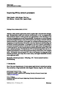
transmission substations. There are international transmission links with Morocco, consisting of 102 buses, 119 lines, 19 transformers, 11 Generators and 74 loads. The grid is shown in Figure 1.
These resources are abundant and have enormous energy potential, however, they are usually broadcasts and not fully accessible, most of them are intermittent, and have distinct regional variability. These characteristics result in difficult, but solvable, technical and economical challenges. Today, significant progress is made in improving the conversion efficiency and collection, lowering the cost of investment and maintenance costs, and increasing the reliability and applicability [31], [32]. The benefits arising from the installation and operation of renewable energy systems are expected to have a considerable impact on energy conservation and reduction of environmental pollution. 3. The west Algerian network model Electricity demand in Algeria is growing a fast rate of about 5% to 7% annually, and will, according to Sonelgaz (Electricity Company of Algeria), require significant additional capacity estimated 9000 MW by 2015. Currently, the west Algerian has around 2,500 MW of installed power generating capacity, but this has not been sufficient to reach demand during peak cooling periods in the summer. Currently, the Algerian government is pushing power conservation measures. In the longer-term, however, Algeria's power sector will need to grow. This will require billions of dollars worth of investments in new generating capacity, plus transmission and distribution infrastructure (i.e., lines and sub-stations) [33]. The electric power network of the west Algerian considered in this study operates at 60, 220 and 400 kV. The transmission system consists of around 3500 km of line and 30
Fig. 1. Schematic diagram of the Western grid of Algeria 400Kv ,220 Kv and 60 Kv, the power system network used in this study.
3.1. Network without devices analyze Based on system data, provided by electrical company of Algeria,it was performed a complete modeling the west Algerian network 2012 using the software Psat, which allows the calculation of the power flow. It includes also the operation and the control of FACTS devices, HVDC and wind power. procedure of simulation:
4
Journal of Electrical Engineering www.jee.ro
a) Open The Psat Tool Box Using The Matlab Software. b) open a new file to build the network with the parameters given by the electrical company, using library existing in Psat. c) Click the open data file so that the load data file page opens. select the file which we need and load it. so that the data file is set. d) Run The Power Flow And The Result Is Viewed In Static Report. The calculation of the power flow is used to compare the results obtained from different network configurations and simulation scenarios. It is performed first for the determination of the initial conditions of the system before the compensation. Indeed, it makes it possible to find the voltages in the different buses figure 2 and losses figure 3.
Fig. 4.Voltage at bus connection in (pu). The table 1 present the different power in the west Algerian network without devices. Table 1. Power of the network without devices Real power Reactive power [MW] [MVAr] Total 1747.28 540.93 generation Total load Total losses
1689.01
658.75
58.27
117.82
3.2. Problems of the West Algerian network
Fig. 2.The nodal voltage network Algerian west (2012) without devices.
Fig. 3.Losses network of the west Algerian (2012) with
According to the results of the power flow Figure 2 ,3 and 4 it can be concluded this network suffers from a problem of power transit especially in the longest lines Such as the line (14-24) and also, lines (2-4),(39-73),(81-85) and (87-92) where we registered the biggest quantity of the losses among 137 lines which existent in this electric network , For example in line (39-73) active losses were 9.7 MW which represents 17 % of the total losses. There is also a problem with the voltage in four buses. At bus 4, the voltage exceeded 1.1pu which is considered as an overvoltage. At bus 73 the voltage was above 0.9 pu i.e. a voltage drop and this was the case of buses 85 and 92. The last problem is that the department of Adrar is isolated and not connected with this network. We propose to solve these
devices.
5
Journal of Electrical Engineering www.jee.ro
problems using the FACTS controllers, HVDC and wind power. FACTS are inserted at the points where problems have been identified like in the line (24) and at bus 4. It is possible to solve these problems by series compensation to reduce losses and parallel compensation to maintain the voltage at the appropriate level. A single device, such as series FACTS, is able to perform both tasks i.e. reduce losses and improved voltage. Taking into account the economic aspect and the complexity of control among the various FACTS devices, the TCSC represent a good compromise solution. The same compensation is introduced for lines (81-85), (87-92) and buses 85 and 92. However, for line (39-73) and bus 73, the problem can be resolved using a series FACTS device, moreover, to benefit from the prevailing weather conditions and abundant wind of the department of Tiaret considered as Algeria’s second windy area, wind turbines can be installed and integrated to the network. In the other longest line (14-24) where a transit power problem was encountered, it is necessary to insert a TCSC. As the department of Adrar is not connected to the network of west Algeria, and at distance of 660km from the city of Bechar the nearest network point, we propose to use an HVDC connection. To benefit from the available renewable energy resources such as wind in the regions of Adrar and Tiaret as shown in Figure.6, two wind farm have been inserted at these buses. The problem of stability of the voltage at this bus of connection of the wind farm, was solved by a parallel compensation like STATCOM.
Table 2. Power of the network with devices
Total generation
Real power [MW] 1721.77
Reactive power [MVAr] 651.36
Generation wind farm1
62.11
/
Generation wind farm2
55.48
/
Total load Total losses
1799.11
681.55
40.26
-30.19
Fig. 5.Comparison between the average speeds of windy sites [33].
The calculation of the power flow of the system after the insertion of FACTS, HVDC devices and wind power are illustrated by the results of Figures. 7, 8 and 9. The table 2 present the different power in the west Algerian network with devices.
6
Journal of Electrical Engineering www.jee.ro
Fig. 6.Diagram of the network West-Algeria (2012) with the insertion of devices.
3.3. Interpretation of results Table 3. Comparison of the results
Results
Fig. 7.Voltages network of west Algerian (2012)
Losses active totals [pu]
Without devices 0.58
With devices 0.40
Voltage at bus(4) [pu]
1.1
1.07
Voltage at bus (73) [pu]
0.77
0.93
Voltage at bus (85) [pu]
0.75
0.84
Voltage at bus (92) [pu]
0.79
0.91
Production fossil [pu]
17.47
17.22
with FACTS.
7
Journal of Electrical Engineering www.jee.ro
4. Conclusion This study has demonstrated the ability of FACTS and HVDC technologies to improve the flexibility of power network. The simulation study was based on a real network topology of the western region of Algeria. The devices used for this control are the TCSC (thyristor Controller series capacitor) and STATCOM (Static Compensator). These devices are able to control the active power and voltage to improve the performances of the electrical network. The STATCOM was used to ensure a good integration of the wind power in the west Algerian network 2012 by providing adequate voltage support at the point of connection. Fig. 8.Losses network of the west Algerian (2012) with devices.
The results obtained show that FACTS and HVDC technologies can contribute effectively to the reduction transmission line losses and improve the quality of the voltage at several buses, also to the integration of the wind power into the network and therefore they will play a vital role in the future power grids. In the future we will improve protection and control to make this network more flexible.
Fig. 9.Voltage at node of connection with STATCOM in (pu)
According to the results obtained in Table 3, it can be noticed that the total losses of the system decreased from 58,2715 MW to 40,2564 MW, i.e. a reduction of 18,0151 MW. This reduction is achieved as a result of the insertion of the TCSC devices in the lines (2-4), (39-73), (6-17) and (8692). Also, the quality of voltage has been improved at bus 4 from 1.103 to 1.07pu, in the bus 73 from 0.77 to 0.93 pu and at bus 85 from 0.75 to 0.84pu and finally in bus 92 from 0.79 to 0.91pu. The integration of wind farms into the west Algerian network 2012 at the two points of Adrar and Tiaret has contributed with 117,479 MW. Voltage support at the connection point of the wind farm was achieved by a STATCOM. The connection of the department of Adrar to the west Algerian network 2012 using HVDC device was done for two reasons, firstly this region was isolated, secondly we benefited from its great potential of wind energy.
Appendix A: HVDC adjustment and parameters Power and Frequency Ratings [MVA, Hz]: [66.97 50] DC Ratings (Vn_dc, In_dc) [kV, kA]: [400 0.5] Transformer Reactances (Xcr Xci) [p.u. p.u.]: [0.1345 0.1257] Tap Ratios (Ar Ai) [p.u./p.u. p.u./p.u.]: [0.975 0.975] PI Regulator Constants (Ki, Kp): [30 25] DC Line Parameters (Rdc Ldc) [p.u. p.u.]: [0.0625 0.200] Rectifier Angle Limits (a_max, a_min) [deg deg]: [120 5] Inverter Angle Limits (g_max, g_min) [deg deg]: [30 18] Reference dc current limits (Ir_max, Ir_min, Ii_max, Ii_min) [p.u.]: [1.2 0.1 1.1 0.0] Current, active power and dc voltage orders [p.u. p.u. p.u.]: [2.63 1 1.0] Control type: Current-control Appendix B:STATCOM adjustment and parameters Power, voltage and frequency ratings [MVA, kV, Hz]: [100 69 50] Gain and time constant of the current control Kr, Tr [p.u./p.u. s]: [50 0.1] Max and Min Current [p.u. p.u.]: [1.2 0.8] Appendix C: TCSC adjustment and parameters Power, Voltage and Frequency Ratings [MVA, kV, Hz]: [100 220 50] Model type: Alpha Operation mode: Constant power flow Scheduling strategy: Constant line power
8
Journal of Electrical Engineering www.jee.ro
Percentage of series compensation [%] : 10 Regulator time constant Tr [s]: 0.5 Alpha_max and Alpha_min [rad rad]: [0.5 -0.5 ] Proportional and Integral gains Kp and Ki : [5 1] XL and XC [p.u. p.u.]: [0.2 0.1] Gain for stabilizing signal Kr [p.u./p.u.]: 10
Acknowledgements We want to thank Dr. Federico Milano for creating the PSAT software, which we facilitate the task of calculation of electric networks.
References [1] Cherif S.: Energy future of Algeria. Faculty of Economics and Commercial Sciences and Management, University of Mohamed Khider-Biskra, june 2011. [2] http://www.energy.gov.dz/français/index.php? page =le-programme-des-energies-renouvelables-et-del'efficacite-energetique. [3] Latorre G., Cruz R., Areiza J. and Villegas A.: Classification of publications and models on transmission expansion planning. IEEE Trans.Power Syst 18, 2003, s. 938-946. [4] Shristha G., Fonseka P.: Flexible transmission and network reinforcements planning considering congestion alleviation. Proc. Inst.Elect. Eng. Gen. Transm., Distrib 153,5, 2006, s. 591-598. [5] Blanco G., Olsina F., Garces F.: Real Option Valuation of FACTS Investments Based on the Least Square Monte Carlo Method. IEEE Transactions on power systems 26, 3, 2011, s. 1389-1398. [6] ABB has delivered more than half of all HVDC projects worldwide, available :http://new.abb.com/systems/hvdc, online: 2016. [7] Mazouz L., Zidi S A., Saadi S., Benmassaoud T and Elaguab M: Hybrid Swarm Intelligence Approach Based PI Regulator for VSC-HVDC Optimal Parameters. Journal of Electrical Engineering 14, 2014, Edition 2, s.355-362. [8] Claus M., Rotzmann D., Sorangr D and Uecker K.: Solutions for Smart and Super Grids with HVDC and FACTS. 17th Conference of the Electric Power Supply Industry, October 2008. [9] Elmajali H D.: Control of Series HVDC Bridges with Different Firing Angles. WSEAS Transactions on Power Systems 9, 2, 2014, s. 418-427. [10] Alvarez S., Ladoux P., Caroll E .: Characterisation of Low Voltage IGCTs (3,3KV) by using and Opposition Method Test Bench. PCIM'04 -International Exhibition and Conference for Power Electronics Intelligent Motion Power Quality, NUREMBERG (Allemagne), Mai 2004. [11] IEEE T&D committee 2000 – CIGRE 2000 WG-B4 04 2003.
[12]
http://www.ece.uidaho.edu/hvdcfacts/Projects T&D committee 2000 – CIGRE 2000 WG-B4 04 2003.
[13] Acha E., Fuerte-Esquivel C R., Ambriz-Perez H., Angeles-Camacho C.: FACTS modeling and simulation in power networks. John Wiley and Sons, LTD, England 2004. [14] Bindeshwar S.: Introduction to FACTS controllers in wind farms: A Technological review. IJREE International Journal of Renewable Enrgy Research 2, 2, 2012. [15] Akram B F.: Interaction between PSS and FACTS Devices in damping power systems oscillations: part I. 7th International Multi-Conference on Systems, Signals and Devices, 2010. [16] Hingorani N G., Gyugy L.: Understanding FACTS:Concepts and Technology of Flexible AC Transmission Systems. IEEE Press, New York, 2000. [17] IEEE FACTS working group, FACTS Applications. Technical Report, 96TP 116-0, 1996. [18] Hingorani N G.: Flexible AC transmission. IEEE Spectrum, 1993, s. 40-45. [19] Saha A., Das P., Chakraborty A K.: Performance Analysis and Comparison of Various FACTS Devices in Power System. International Journal of Computer Applications 46, 15, 2012, s. 887-975. [20] Mathu R M., Varma R K.: Performance Analysis and Comparison of Various FACTS Devices in Power System. John Wiley and Sons LTD, England 2002. [21] Maikandasivam S., Nema R K., Jain S K.: Fine power flow control by split TCSC. Electrical Power and Energy Systems 45, 2013, s. 519-529. [22] Hari Krishna K., Chandra Sekhar K.: Simplified PSO based controller design for AGC in deregulted power systems with TCSC,HVDC and SMES. Journal of Electrical Engineering 16, 2016, Edition 3, s.155-163. [23] Nagalakshmi S., Kamaraj N.: On-line evaluation of loadability limit for pool model with TCSC using back propagation neural network. Electrical Power and Energy Systems 47, 2013, s. 52-60. [24] Lakdja F., Gherbi F Z., Berber R., Boudjella H.: Optimal TCSC placement for optimal power flow. Journal Electrical Engineering 63, 2012, s. 316-321. [25] Guentri H., Lakdja F., Laouer M.: The opportunity of power electronics on improving the quality of voltage and power flow in the west Algeria network. Energy Procedia 50, 2014, s. 870-881. [26] Venugopal D., Jayalaxmi A.: Improving Congestion of Transmission Systemby Optimal Placement of FACTS Devices. Journal of Electrical Engineering 15, 2015, Edition 2, s.30-36. [27] Hanson D J., Woodhouse M L., Horwill C., Mankhouse D R and Osborn M M.: STATCOM: A New Era of Reactive Compensation. Power Engineering Journal, 2002, s. 151-160. [28] Abido M A.: Power system stability enhancement FACTS controllers: A review. The Arabian Journal for Science and Engineering 34, 1B, 2009.
9
Journal of Electrical Engineering www.jee.ro
[29] Qiao W., Ganesh K V., Ronald G H.: Coordinated reactive power control of large wind farm and a STATCOM using heuristic dynamic programming. IEEE Trans. Energy Convers 24, 2, 2009, s. 493-503. [30] Aouzellag Lahaçani N., Aouzellag D,.: Optimal Power Flow using FACTS Devices in Electrical Network with Wind Generator. Journal of Electrical Engineering 16, 2016, Edition 3, s.463-473. [31] Abdul R., Sikanda A A., Asif M., Saleem R S., TaufiqYap Y H., Michael K D. and Razif H: Renewable energy deployment to combat energy crisis in Pakistan. Sustainability and Society 6, 2016:16 [32] Soteris A K.: Solar thermal collectors and applications. Progress in Energy and Combustion Science 30, 2004, s. 231-295. [33] Dib D., Abdelhakim B., Metatla S., Soufi Y.: The Algerian Challenge between the Dependence on Fossil Fuels and its Huge Potential in Renewable Energy. International journal of renewable energy research 2, 3, 2012. [34] National Research Project, Perspectives du pompage éolien en Algérie, domiciled in CDER. ALgeria, 2008.
10