1
Journal of Ambient Intelligence and Smart Environments 1 (2013) 1 IOS Press
Incremental Design of Adaptive Systems Sven Tomforde a,∗ , and Christian Müller-Schloer b a Universität
Augsburg, Organic Computing Group, Eichleitnerstr. 30, 86159 Augsburg, Germany E-mail:
[email protected] b Leibniz Universität Hannover, System and Computer Architecture Group, Appelstr. 4, 30167 Hannover, Germany E-mail:
[email protected]
Abstract. Current research initiatives like Organic Computing (OC) and Intelligent Environments (IEs) aim at building technology-driven embedded systems that are aware of the conditions in the real world, derive plans of how to act, and proactively manipulate their environment to serve the user. As a result, novel systems according to these initiatives are characterised by a high degree of adaptivity, user-sensitivity, robustness and reliability. Adaptivity means that for such systems we defer a part of the design process from design time to runtime. Therefore we need a runtime infrastructure, which takes care of runtime modifications. And we need a meta-design process responsible for the parametrisation of the runtime infrastructure. This article presents such a meta-design process to develop such systems in a unified way in order to handle the growing complexity in technical systems by focusing on adaptation and self-optimisation capabilities. A promising application for organic concepts and a large-scale testbed for IEs is the control of road traffic signals in urban areas. This article exemplarily applies the proposed design process to a traffic scenario and evaluates it in a realistic setting modelling the (football) stadium environment in Hannover, Germany. Thereby, the significant benefit of the adaptation component developed through the design process is demonstrated in terms of traffic-relevant metrics like delays and energy consumption. Keywords: Organic Computing, Intelligent Environments, Design Process, Traffic Control, Self-adaptation
1. Introduction Nowadays, the vision of Ubiquitous Computing as formulated by Marc Weiser in 1991 [64] becomes increasingly realistic. Technology has become a fundamental part of human lives and supports us embedded in the environments that we encounter on a daily basis. Developments like computational and artificial intelligence allow engineers to build technology-driven environments, typically referred to as Ambient Intelligence [29], where systems observe the conditions in the real world, derive plans of how to act best in this environment, try to draw conclusions from observed behaviour, and finally act pro-actively by applying actions and manipulating this environment. These resulting spaces are called Intelligent Environments (IEs) [16]. Organic Computing (OC), cf. [38,39], is a recent research area which focuses on building self-organised * Corresponding
author.
systems to solve complex problems. Autonomous entities are acting without strict central control and achieve global goals although their decisions are based on local knowledge. Due to the complexity of the particular tasks, not all possibly occurring situations can be foreseen during the development process of the system. Therefore, the system must be adaptive and equipped with learning capabilities, which leads to the ability to learn new strategies for previously unknown situations and, therefore, to a self-optimising system behaviour. IEs are characterised by exactly the same requirements [37]. Until now, research in IEs mainly focused on making isolated rooms smarter by interconnecting a set of embedded devices and developing intelligent strategies. Examples include homes, libraries, or cars [16]. OC has a similar goal but started from a different perspective and a widely different motivation (see Section 2). In general, both initiatives aim at integrating dynamic system behaviour, learning capabilities, and therefore self-organisation in embedded technology in
c 2013 – IOS Press and the authors. All rights reserved 1876-1364/13/$17.00
2
S. Tomforde and C. Müller-Schloer / Incremental Design of Adaptive Systems
order to build systems dealing with complex problems and simultaneously providing properties such as quality, cost, efficiency, usability and reliability. These “intelligent” systems (or, as a set of systems, these environments) have to be to a high degree adaptive, usersensitive and robust. Thereby, the OC focus has been mainly set on developing system architectures and enabling technologies, while IE investigated mostly “the intelligence” in the interconnected world. In this context, we understand the term “intelligent” as placeholder for all kind of mechanisms from IT- and other pervasive computing technologies that pro-actively try to achieve specific goals for the user, the environment or both (i.e. to improve the performance of activities and user experience, or to protect people and enable higher-quality lifestyles for participants). Hence, a promising first step towards merging forces of both directions is to make use of a unified OC approach to design intelligent and adaptive systems in combination with a standardised way to organise the resulting design process. This article describes a possible solution for such an attempt. The basic idea of OC is to move design time decisions as typically taken by engineers to runtime and into the responsibility of the OC system itself. Hence, such a system requires a self-adaptation mechanism (the Observer/Controller component in the context of OC [57]) which is generic in the sense that it is not designed specifically for each application. Instead, the generic mechanisms form a runtime infrastructure which must be adapted to the particular problem using well-defined parametrisable steps. This leads to a meta-design process whose results provide the parametrisations of the online adaptation mechanism. This article is organised as follows. Section 2 describes how OC achieves the desired functionality at design level. Additionally, the existing design processes are briefly discussed in order to motivate the need of a novel OC-specific process to develop intelligent systems. Afterwards, Section 3 introduces this novel process, which is then evaluated in an exemplary scenario from the urban traffic domain (Section 4). Finally, Section 5 concludes the paper and gives an outlook to current and future research challenges.
2. Organic Computing Systems Organic Computing (OC) is based on the insight that we will soon be surrounded by large collections of au-
tonomous systems, which are equipped with sensors and actuators, are aware of their environment, communicate freely, and organise themselves in order to perform the actions and services that seem to be required [38]. Consequently, OC aims at designing technical systems which are equipped with sensors (to perceive their environment) and actuators (to manipulate it). Such an organic system adapts autonomously and dynamically to the current conditions of the perceived environment. This adaptation process has impact on the system’s performance, which is continuously optimised by the organic system itself. OC systems are characterised by self-X properties (similar as e.g. formulated for the Autonomic Computing initiative in [31]). This section briefly discusses the general architectural concepts for organic systems and defines the need of an OC-specific meta-design process to be able to incrementally build adaptive systems. 2.1. Organic Computing and Intelligent Environments Compared to the domain of Intelligent Environments (IEs) [16], the OC initiative has its focus on developing suitable system architectures and design methodologies for large-scale interconnected systems and technologies to ensure self-organised solutions where a system-wide operation and optimisation is not possible any more. Therefore, OC developed varying collaboration schemes (e.g. [30] in the context of robot teams or [58] in the traffic domain). Here, the IE community investigated more isolated scenarios with less attention on the interconnection aspect. Examples for these OC systems include wide-scale networked systems like energy-infrastructure [2], Intelligent Surveillance systems [15], production systems [28], or trusted desktop grid [32] and data communication systems [56]. Furthermore, adaptive and robust behaviour has been investigated exemplarily for partially isolated stand-alone systems like more-armed walking machines [26], motion-detection [62], or offhighway machines [66]. Some researchers in the IE domain already considered adaptive concepts in terms of self-adaptation at runtime (see e.g. [37,13]). A unified approach to achieve the desired characteristics as presented in this article is not available, yet. Moreover, IEs have a strong focus on the user or participant. In OC, we typically model the user or use an abstract possibility to change the system. Direct user interaction – e.g. in terms of
3
S. Tomforde and C. Müller-Schloer / Incremental Design of Adaptive Systems
System under Observation and Control (SuOC) The SuOC is the “productive” part of the system and is assumed to be functional even if higher-layered O/C components may fail. Observer The observer is responsible for monitoring the SuOC’s state and the environmental dynamics. The gathered data is analysed and augmented to an appropriate description of the current situation for the whole system. Controller The controller evaluates the situation parameters and influences the SuOC based on this information and with respect to the goals given by the user. 1 OC is the acronym for Organic Computing while O/C refers to “Observer/Controller”.
observes
observer observer reports
controller controller
organic system
input
output
SuOC SuOC
Fig. 1. Generic Observer/Controller architecture [48].
The Multi-level O/C framework (MLOC) for learning and self-optimising systems [55] defines the architectural design as depicted in Fig. 1 in more detail. Systems founding on the general MLOC design are able to adapt themselves to changing environments, to learn the best adaptation strategy, and to explore new behaviours autonomously. Figure 2 illustrates the encapsulation of different tasks by separate layers. Layer 0 processes the productive logic (the SuOC). Layer 1 establishes a control loop with safety-based on-line learning capabilities, while Layer 2 evolves the mostpromising reactions to previously unknown situations. In addition, Layer 3 provides interfaces to the user and to neighbouring systems.
Layer 3
Monitoring
Layer 2 Collaboration mechanisms
OC systems are characterised by the need of an adequate response to environmental and internal changes which leads to an adaptive system behaviour and incorporates further aspects like robustness and flexibility. This adaptive behaviour is achieved by a regulatory feedback mechanism that is capable of monitoring, analysing, and reacting to changing conditions. Figure 1 illustrates the generic Observer/Controller (O/C)1 architecture [48] as proposed by and widely used in the OC community. The O/C architecture constitutes a generalised way to achieve controlled selforganisation in technical systems. It consists of three major components:
goals
observation model
Neighbouring Systems
2.2. Observer/Controller Design
selects observation model
controls
adapting the system’s goal at runtime [8] – have been only investigated exemplarily, so far. Another strong difference between IEs and OC is the underlying element that is observed and controlled. Here, OC currently focusses on technical systems only. The major perspective is that all technical systems surrounding should adapt autonomously to the user’s needs (cf. also Ubiquitous Computing, [64]) and without his intervention. In some application scenarios, the OC initiative already investigated possibilities to directly influence users; for instance, routing in traffic management system provides route recommendations for individual drivers. Here, the approach is to support users with decision alternatives and an automated rating rather than directly controlling them. In contrast, the user itself might be seen as the element to be observed and controlled in IEs. This, however, will not be part of this article.
Offline learning
Observer
Layer 1
Goal Mgmt.
Controller Simulator
User
EA
Controller
Parameter selection
Observer
modified XCS
Layer 0 Detector data
System under Observation and Control
Control signals
Fig. 2. The Multi-level Observer/Controller framework [55].
The system’s design corresponds to the generalised Viable System Model (VSM), see [9]. According to this model, each organisation of enterprises and each organism itself can be described in a unified way. The task assignments of Layers 0 to 2 are similar to those of the VSM with types 1 to 3 (productive type 1, coordinating type 2, and optimising type 3). Type 4 – plan-
4
S. Tomforde and C. Müller-Schloer / Incremental Design of Adaptive Systems
ning – is covered in a distributed manner by collaboration among (equal) elements, cf. Layer 3. Within OC, these collaboration mechanisms are subsumed under the term “Social layer” (where the “society” is the set of technical subsystems participating in the selforganisation process). Only type 5 of the VSM – the decision level – is not explicitly foreseen and assumed to be situated in the user’s area of responsibility. Besides these minor points, the main difference between our model and the VSM is that the VSM is a general model for organisation and not explicitly technical. MLOC is a technical realisation of the different control types. The following part of this section explains MLOC’s layers and their particular tasks in more detail. 2.2.1. Layer 0: System under Observation and Control The lowest layer of the architecture encapsulates the productive part of the system (the SuOC). This SuOC can serve various purposes, a short overview of already investigated examples is given in [57]. Higher layers of the architecture monitor and adjust (if necessary) the parameter configurations of the productive system in discrete time intervals. In this context, the set of all possible configurations at runtime define the configuration space. As OC focuses on assigning responsibilities for complex tasks to large populations of smaller entities, the SuOC in Figure 2 might refer to single systems or groups of autonomous systems. Independently of the number of involved entities, the SuOC has to fulfil a couple of basic requirements to be controllable by MLOC: a) its behaviour and its environmental conditions have to be observable, b) its performance has to be measurable according to a goal given by the designer or user, and c) it has to possess a set of variable parameters that can be adapted at runtime and that have certain impact on the performance of the system. 2.2.2. Layer 1: On-line Reconfiguration and Learning Upon the SuOC, the Layer 1 component establishes a first regulatory feedback mechanism by observing the SuOC’s state and adapting its parameter configuration accordingly. Therefore, the observation task consists of the five consecutive steps monitoring, preprocessing, data analysis, prediction, and aggregation. The resulting aggregated situation description is passed over to the controller which has to decide about necessary modifications of the SuOC’s parameter configuration. This decision process can be realised by a modified variant of Wilson’s eXtended Classifier
System (XCS, see [65]) which is a rule-based selection technique. Rule-based systems play an important role in a variety of Intelligent Environments (see [49]). Our modified variant stores mappings between situation descriptions and corresponding actions in terms of parameter configurations and restricts the set of selectable rules due to safety and real-world requirements (see [55] for details and an investigation of alternative techniques, and [51] for details about the overall behaviour in terms of convergence). Thereby, a similarity metric is used which quantifies how close situations are to others (by comparing the condition parts of the rules) and restricting the potentially selectable set of rules by considering a minimum similarity. Furthermore, it replaces the original XCS methods to introduce new rules by assigning this task to Layer 2 of the architecture. 2.2.3. Layer 2: Off-line Optimisation In case of unknown situations or absence of rules with satisfying performance, control is transferred to Layer 2. While Layer 1’s controller reacts on observed situations with the most promising action of its behavioural repertoire, Layer 2 evolves new rules for the corresponding situations – following the assumption that the unknown situation is expected to occur again later on. Therefore, the Layer 2 observer monitors Layer 1 and recognises the demand of new rules. Based on this trigger, the controller at Layer 2 evolves configuration settings by using an optimisation heuristic and repeatedly analyses them using a simulation tool. This bears the advantage that newly created configurations are not directly used in the live system, as this could cause the system to perform badly or even malfunction. Only those configurations qualifying in the simulator of Layer 2 are passed back to Layer 1, and may then be applied in the real world as soon as the situation re-occurs. This separation of concerns between Layer 1 and 2 serves two purposes: (1) it enables the system to react immediately (although this action is not necessarily optimal) and (2) it allows for a gradual improvement of the rule base in Layer 1 by using the learning mechanism on Layer 2. 2.2.4. Layer 3: Decentralised Collaboration The basic system is defined by the Layers 0 to 2 and describes an isolated and autonomously acting system. Through the additional Layer 3, communication among and collaboration between neighbouring systems is enabled. Similarly, Intelligent Environments consist of interconnected devices which defines the need of cooperation between elements. In this con-
S. Tomforde and C. Müller-Schloer / Incremental Design of Adaptive Systems
text, collaboration is application-specific and ranges from exchanging sensor data (for Layer 0) over negotiating parameter settings (for Layer 1) to collaboratively searching for optimal situation-action mappings (at Layer 2). In addition, the user of the system can access the interfaces provided at Layer 3 to monitor current measurements, analyses, and objectives. 2.3. The Need of an Organic Computing-specific Design Process OC systems are characterised by attributes like self-organisation, self-configuration, self-protection, or self-explanation. In consequence, this means that at least a part of the design effort moves from design time to runtime. OC therefore means to move design time decisions to runtime. This relocation of design activities comprises five aspects: 1. Classically, a designer explores the possibilities of the design space, which requires experience as well as creativity. Within an OC system, the system itself has to explore the configuration space using its Layers 1 and 2. This means that in OC systems an online configuration space exploration is performed instead of a design space exploration. The design time effort is here to restrict the configuration space in such a way that it should usually be smaller than the design space in order to bound search-time. This is e.g. achieved by excluding illegal and not-promising configurations beforehand (in this context, notpromising means that the designer can provide his domain knowledge as rules: i.e. dependencies between parameters might exist in such a way that increasing one should always lead to increasing the other one as well). 2. The OC system can be modelled as an agent moving through the configuration space in search of the highest fitness. This fitness landscape is not only unknown to the agent but also time-dependent and self-referential [12]. I.e. it changes depending on the actions of the agent itself and all other agents. This optimisation takes place at runtime at Layer 2, hence only limited computing resources and time are available. 3. Searching the configuration space relies on validating possible solutions online. Since approaches like trial-and-error mean that bad (or illegal) solutions are tried out in reality, OC proposes to use a sandbox approach where solu-
5
tions are validated in a simulated environment. In the proposed architecture, the Layer 2 mechanisms constitute such a sandbox. Simulation (and verification) is usually time-consuming, and it requires an accurate description of the system. Moreover it requires stimuli reflecting the future real situation as closely as possible. 4. Classical design processes freeze the design at a certain point in time and the result goes into production. OC systems have to work without freezing. Hence, the runtime reconfiguration process is seamless and consequently all, even the higher-level, design decisions must be adaptive and changeable at runtime. OC systems are capable of revising almost every design decision in terms of software or hardware reconfigurations. For hardware changes FPGA technology can be used. Software can be changed at runtime, at least in principle. 5. Today, all design steps are model-based in the sense that models are used at design time to validate the system before it is actually built. In OC, however, two different flavours of these models have to be distinguished: a) prescriptive models reflect the classical top-down enforcement and b) descriptive models reflect the actual system state. Both models are not necessarily always consistent. Hence, OC has to find mechanisms which can resolve or minimise the possible contradictions. This corresponds to a runtime version of YoYo design from classical design processes. In general, runtime modelling is currently increasingly investigated in the context of self-adaptive systems (cf. e.g. [1]). The above list describes the most important requirements OC has for an appropriate design process. In general, we can observe a dichotomy that partitions adaptive systems according to the targeted functionality: One part is (similar to traditional approaches) responsible for the productive logic part (although the focus is on smaller entities). The other part implements the adaptivity (or better organic) aspects. Traditional design processes target the productive part only. Hence, it is assumed that the aforementioned requirements for the organic aspect are novel and therefore not covered by these approaches. The following part of this section substantiates this assertion by briefly discussing traditional design concepts and explaining the problems when applying them to the design of OC systems.
6
S. Tomforde and C. Müller-Schloer / Incremental Design of Adaptive Systems
2.4. Traditional Design Processes The organisation and definition of design and development processes has gained a high degree of attention by research and industry since fast and successful projects are a key factor for controlling costs. As a result, widely varying terminology can be found as well as approaches following different directions. Therefore, a common understanding of the most important terms in this context is needed at the beginning. Design Decision: The design process is defined as the period in time from specifying an initial demand of a new system or software until its delivery to the customer (or potentially even longer when taking product care and maintenance into account). Independently of how the process is organised and structured, it consists of several consecutive parts where each resulting artefact is increasingly detailed. Thereby, various decisions have to be taken by weighing up the pros and cons of alternative concepts. Each of these steps of preferring one alternative against another is referred to as design decision. Capability: The system to be developed during the process serves a specific purpose. Thereby, we distinguish between the productive and adaptable part and the actively adapting part (i.e. the organic control mechanism). The function and performance of the productive part is described initially during the requirement analysis phase. It results in a system specification. On the other hand, the adaptivity-related part of the process defines the envisioned degree of autonomy. Thereby, the designer has recourse to a set of consecutive organic functionalities with an increasing degree of self-management. Examples include learning, discovering of novel behaviours, or social collaboration. We call these different adaptivity-related functionalities OC capabilities. Design Phase: The overall process to develop the desired system functionality is sliced into increments or portions. Each of these increments serves a specific purpose and therefore organises the process according to the ongoing timeline of the project. Typically, each of these slices adds further details or functionality to the system and is organised from the requirements down to the deployment. Following these slices as organisational structure, the process consists of several consecutive phases with each phase equal to a subset of these slices. In the following, we briefly discuss the most prominent traditional design processes. The Waterfall model [50] distinguishes between several consecutive devel-
opment phases. As already expressed by its name, design decisions are processed in steps from defining the requirements towards the final product. The V-model [20] describes a development process for software or hardware systems which is based on the Waterfall model. The name V-model describes the shape of the descent through the abstraction levels defined by the steps of the design process: starting with describing a general concept of operations, the system definition is refined afterwards with decreasing abstraction until a detailed design exists, which is implemented accordingly. Immediately after finishing the implementation, the abstraction layers are processed upwards by performing the associated tests from integration to user level. Hence, the model’s horizontal and vertical axes represent the time or project completeness (horizontal axis) and the level of abstraction (coarsest-grain abstraction uppermost), respectively. In order to be able to apply the V-model to the management of a system of systems, is has been extended to the Dual-Vee model [21]. Here, an additional distinction of tasks is introduced with the view on an intersecting architecture and an entity aspect. Another related approach has been presented by Gajski with the Y-Chart model [23]. It is mainly used for the design of Integrated Circuits. The chart specifies three axes representing a) the system behaviour (i.e. function or specification), b) the system structure (i.e. connected components or block diagrams), and c) the physical design (i.e. the physical layout). Furthermore, the chart works on different abstraction levels identified by concentric circles around the origin. In this context, Gajski names the four typical levels transistor, logic, register transfer and system level as most prominent examples for these abstraction circles. The initial model has been extended to form an X-Chart in [47] which additionally takes the aspect of testing into consideration. The Spiral-model [10] (or spiral lifecycle) is another software development process which aims at a combination of a detailed design (following the waterfall approach) and an iterative prototyping in the sense of top-down vs. bottom-up approaches. The focus is especially set on large and complex projects. Each phase is defined as a process from defining the goals until delivering the result to the customer, which is responsible for reviewing the progress at this point. Hence, the process is divided into sub-projects that are performed consecutively. Most of these approaches are located in the broader field of iterative and incremental development [33].
S. Tomforde and C. Müller-Schloer / Incremental Design of Adaptive Systems
This method describes an incremental software system development process where incremental means to take advantage from experiences with previous versions of the developed system and iterative means to structure the process according to phases following the waterfall approach. The basic idea is to start building the system with subsets of the requirements adding increasing functionality in the succeeding phases until a fully fledged system is implemented. Thereby, the design of the system is revisited and possibly modified at the end of each of the phases leading to simple documentdriven milestones [6]. An overview on the history of iterative and incremental development is given in [33]. In the domain of hardware design (especially when using the hardware description language VHDL [42]), the Design Cube Model [17] considers three independent property scales: the design view, the time, and the value representation. Each of these aspects is further structured according to an increasing abstraction level, i.e. the design view from structure to data flow to behaviour. The result is a design flow representation from the gate level to the algorithmic level. The aforementioned design approaches all try to define the whole system using requirements and then organise the process as a hierarchical top-down method. In contrast, a bottom-up approach works on developing sub-systems and aggregating or combining them later on to build the desired system functionality. Hence, we can distinguish between the leaf level (i.e. the lowest level in the hierarchy) and the system level (with leaf levels being subroutines, procedures or, in case of hardware, building blocks for the system level). Besides these two basic concepts, hybrid solutions are possible, with what classical system engineers call “YoYo” [27] design being the most popular variant. Here, the term YoYo refers to switching back and forth between the two contrary approaches bottom-up and top-down [52]. The Rapid Application Development (RAD) [35] mechanism goes back to the mid 1970s and the New York Telephone Company. They structured their system development according to four phases: Requirements Planning (system planning and analysis of the system development lifecycle based on an agreement between users, managers, and IT staff members), User Design (interaction between system analysts and users about development models and prototypes), Construction (programming and application development), and Cutover phase (i.e. data conversion, testing, changeover to the new system, and user training).
7
Inspired by chaos theory, the Chaos model [46] states that traditional models have their advantages in managing timings and human resources, but have problems with providing methods to fix bugs or solve occurring technical problems. On the other hand, those mechanisms specialised in bug fixing and solving occurring problems mostly have their disadvantages in scheduling and response to customer demands. Therefore, a combination of both approaches is promising. The leading idea here is to resolve the most important incomplete programming task first. Thereby, importance is defined based on the three attributes big (in the sense of providing functionality to the customer), urgent (has to be done before other tasks), and robust (robust tasks are trusted and tested). Furthermore, resolving a task means to bring it to stability instead of completely finishing it. The most recent approach to software development is based on agile methods [18]. Agile methods are organised according to an iterative development but focus on lighter and more people-centric viewpoints than traditional approaches. Therefore, such an agile process decreases the amount of planning and replaces it by direct feedback from the customer using regular tests and fast releases of the software to be developed. Several different approaches to agile methods exist, with Extreme Programming [7] being probably the most popular one. Here, frequent releases are focused (and thereby very short development cycles) with direct feedback of the customer. Furthermore, elements like pair programming, writing unit tests before code, implementing features only when actually needed, and continuous communication with the customer are advocated. Finally, researchers focused on building reliable software in the sense of guaranteeing the system’s correctness (see e.g. [24,11]). Therefore, formal specification and verification are used in order to demonstrate that an implementation is consistent with the initial requirements of the customer. In this context, the consistency demonstration problem is solved by a decomposition in a set of smaller and thereby simpler sub-problems. Current research in the context of OC extends the approach of formal verification by introducing behavioural corridors for self-organised (and hence organic) systems and guaranteeing to keep the system’s behaviour within these corridors [40]. A good overview of current design methodologies can be found in [43]. All the aforementioned design processes lack the possibility to apply them to the development of OC
8
S. Tomforde and C. Müller-Schloer / Incremental Design of Adaptive Systems
systems due to a variety of reasons. First, the most important OC aspect of moving the design time optimisation process into the responsibility of the system itself at runtime is not addressed. Furthermore, OC’s structure is aligned according to the capabilities instead of the time-line. Probably the YoYo approach is closest to what we want to achieve with OC systems in terms of changing between top-down and bottom-up constraints. However, YoYo design is meant as a design-time process only. In OC systems, all (including higher-level) design decisions have to be revised continuously – where this set of revisable decisions is limited to runtime-reconfigurable software or hardware solutions. On the other hand, formal approaches are hardly applicable due to vast situation and configuration spaces and the entailed impossibility to foresee all potentially occurring situations and best responses at design time. In addition, the general OC design as outlined in Section 2.2 requires a meta-design process including runtime reconfiguration rather than a standard organisational process structure for the design time part. The architectural concept as illustrated by Figure 2 specifies three layers on top of the classical productive part of the system – comprising in total the application-independent self-adaptation mechanism. The task of an OC design process is to adapt this generic mechanism to the particular problem using well-defined parametrisable steps. Therefore, the next section introduces a novel design process to incrementally design adaptive systems based on the OC methodology.
3. The Organic Computing Design Process The OC methodology as developed during several research projects (cf. e.g. [39] for an overview) is characterised by a high degree of modularity. Depending on the specific application and the adaptivity requirements of the designer, an OC system can be built with a range of different OC capabilities (such as learning vs. fixed, with vs. without off-line learning, or with vs. without social interaction). This means that an OC system can be built by adding extension stages to an existing system. This limits the design and validation effort to a reasonable degree according to the specific needs. Modularity has the additional advantage that the design process can be planned along the time axis as a sequence of three well-defined design phases, although the initial idea is to focus on the capabilities rather than on the time. With each phase, the OC-enhanced system
Fig. 3. Degree of OC capability and necessary design decisions.
gains in terms of adaptivity and autonomy. More autonomy, however, entails more effort for the validation of the system. Similarly, the need of novel concepts for designing and developing systems has also been identified in the context of research on IEs (see e.g. [14]). In the following we describe first the modularity in terms of OC capabilities, then the design phases over time. 3.1. Organic Computing Capabilities The general architecture of OC systems according to the MLOC framework as depicted in Figure 2 describes a canonical way of adding self-organised adaptivity and robustness functionality to a productive system. Thereby, the productive part (i.e. the SuOC) is assumed to be handled as a black box in the sense that the control mechanism defined by higher-layered O/C components does not need detailed knowledge about what certain variable parameters mean. The control mechanism of OC systems as realised by O/C components can be simple or sophisticated. Depending on the design effort, OC systems with five degrees of adaptivity can be provided. With increasing degree, an OC system has more capabilities to observe the environment and to react appropriately. Consequently, the design of a system with a lower degree of capabilities requires fewer design decisions. Figure 3 shows the capabilities and the corresponding design decisions. In the following, we discuss the different capabilities as depicted in the figure in detail, followed by the definition of the resulting design decisions. Capability 1 (OC-ready): An OC-ready system (Figure 4) is prepared for the later addition of an (possibly multi-level) Observer/Controller architecture. For an OC-ready system it is required that the major subsystems are equipped with two OC-specific interfaces, namely an observation and a configuration interface. They specify which parameters from within
S. Tomforde and C. Müller-Schloer / Incremental Design of Adaptive Systems
the sub-system are made visible to the outside, and which parameters of the subsystem can be controlled from the outside, respectively. An OC-ready system has no adaptive capability, so far. For this, an Observer/Controller would be necessary which is added only in the next step.
9
not yet the capability to invent new rules. It is confined to a predefined rule set. Its only freedom is to select from the fittest rules.
Fig. 4. Capability 1: OC-ready.
Capability 2 (Non-learning adaptive): A “Nonlearning adaptive” system (Figure 5) is the simplest case of adaptivity. Such a system contains an Observer/Controller. The decision mechanism within the controller implements a fixed mapping from situation descriptions (observer output) to control parameter settings. The decision mechanism requires a similarity metric to decide between different control parameter sets in the situation feature space in order to cover the complete search space (which is generally characterised by continuous values).
Fig. 6. Capability 3: Adaptive with online learning.
Capability 4 (Adaptive with offline rule generation): Offline rule generation adds the capability to invent new rules (Figure 7). Since rules, which have been generated by e.g. an Evolutionary Algorithm (see e.g. [3]), can be fundamentally faulty, they must be validated before they are used in real life. Therefore, a validation method for eliminating detrimental rules has to be used in this stage. Validation can be simply syntactical, or it can be simulation-based.
Fig. 5. Capability 2: Non-learning adaptive.
Capability 3 (Adaptive with online learning): Online learning requires feedback of rewards or punishments assigned to previous decisions by a reward mechanism. Such a reward (or punishment) is measured according to the degree of achievement of a defined system performance. Rewards increase the fitness value of the rule, which was responsible for the underlying action. Higher fitness values increase the probability for a certain rule to be selected. An “Adaptive with online learning” OC system (Figure 6) has
Fig. 7. Capability 4: Adaptive with offline rule generation.
Capability 5 (Adaptive with offline rule generation and cooperation): Social interaction is necessary if agents want to cooperate to achieve a common goal (Figure 8). Cooperation might involve e.g. the agreement on a certain synchronisation sequence, or possibly the exchange of rules in order to speed up learning.
10
S. Tomforde and C. Müller-Schloer / Incremental Design of Adaptive Systems
Fig. 8. Capability 5: Adaptive with offline rule generation and cooperation.
3.2. Design Decisions The OC capabilities as introduced in the previous section are achieved by adding an increasing degree of adaptivity to the system. Thereby, each capability requires certain O/C functionality to enable the desired behaviour. As this functionality has to be added by a system engineer, we refer to a set of six consecutive design decisions that have to be taken – namely the six building blocks from the Figures 4 to 8. These design decisions form the OC meta-design process. (1) Observation model: The first design decision is concerned with the attributes to be observed. Thereby, we distinguish between a SuOC part at Layer 0 and an observer part at Layer 1. For the former part, the designer has to specify the attributes of the production system that should be accessible by higher-layered observers. All internal and environmental attributes with impact on the adaptation or with impact on the process of measuring the system performance need to be available to these observers. Hence, this is the first step towards “OC-readiness” of a SuOC. The latter part is related to the observer as this component must be implemented and configured. Thereby, the designer has to provide a more detailed runtime observation model. This model defines which attributes are relevant for the situation description that serves as basis for the controller’s decision process. It also specifies (if applicable) which attributes should be augmented with prediction values (and which prediction techniques should be used), which attributes should be processed by emergence detectors (e.g. using the quantification method
as presented in [19]) or by statistical operations, and which attributes are used to assess the current performance of the system. (2) Configuration model: The second design decision is again partitioned into a SuOC and a controller part. The SuOC part is needed to define the configuration interface to the productive system – which parameters of the SuOC can be altered at runtime in general? The controller part specifies the SuOC parameters that are actually altered and defines boundaries for a parameter within that the controller can select the configuration. Furthermore, correlations between parameters might be available (e.g. a constraint between two or more parameters like: if parameter1 > value1, then parameter2 < value2) to guide the controller’s learning strategy. (3) Similarity metric: Due to the possibly vast situation and configuration spaces, OC systems have to cope with an unbounded number of possibilities to configure the SuOC. In order to initially close the control loop by activating a rule-based reconfiguration mechanism, a quantification of similarity between situations is needed. This similarity serves as basis for choosing the best available configuration for the currently observed situation. Furthermore, a quantification of similarity allows to classify situations and create groups of them (i.e. by introducing intervals and thresholds) for further extensions. The result is a discretised situation space and a possibility to recognise previous situations and experiences. Experiences are an important prerequisite to learn automatically and therefore to improve the quality of the adaptation process over time. Typically, metrics like the Euclidian distance are used to define the similarity as situations can be modelled as vectors of real values (see [55] for alternatives). (4) Performance metric: Classical system development is based on (mostly hard-coded) implicit goals. In contrast, OC systems have to deal with explicit goals that are user-configurable at runtime – the O/C component uses these goals to guide the system’s behaviour. Automated (machine) learning needs feedback to distinguish between good and bad decisions without the need of an external expert. In this context, feedback is a quantification method for evaluating the system performance at runtime. It is derived from observations in each step of the O/C loop. Therefore, it should be fast to compute and adjustable. This means that the designer has to provide quantifications for possible goals that can be modified and re-arranged at runtime by the user of the systems.
S. Tomforde and C. Müller-Schloer / Incremental Design of Adaptive Systems
(5) Validation method: Automated machine learning at runtime has two severe drawbacks: a) it is mostly based on trial-and-error and b) it needs a large number of evaluations to find the best solution. Both aspects are unacceptable in real-world systems! The solution is to divide the learning task into two parts. Online learning works on existing and tested rules only and derives the best possible response from a limited choice. In addition, offline learning in an isolated environment (a sandbox) explores novel behaviour while not affecting the system’s productive part. In order to discover best parameter configurations for certain situations, three approaches are possible: computation (if available, use a mathematical model to compute the best action for an observed situation), approximation (if available, use approximation functions), and simulation (test actions under realistic conditions and therefore evaluate their behaviour in a specific situation). The former two are seldom available, but would be favoured over the latter one due to quality and time reasons. However, the simulation approach will be the only available in most cases – but it is characterised by the drawback of being time-consuming and computationally intensive. Still, in our experience, simulation can be faster than real world evaluations in certain cases. (6) Cooperation method: OC postulates the distribution of computational intelligence among large populations of smaller entities. Smaller and less complex elements (compared to the traditional monolithic systems) cooperate to achieve common goals. In order to allow for such a division of work between a set of selfmotivated elements, communication and social interaction are needed. Current research in designing OC systems is mainly concerned with such collaborative behaviour (see e.g. [25]). 3.3. Design Phases The idea of OC is to move design time decisions to runtime. At runtime, the systems make their decisions autonomously. Depending on the application, this is potentially dangerous. This means that the design process has to be planned carefully such that the power of decision is transferred gradually from the designer to the O/C structure. Three main design phases are defined, with each phase resulting in a system with increasing autonomy and requiring more validation (Figure 9): – Phase 1: Preparation (OC-ready) – Phase 2: Evaluation (Open O/C Loop)
11
– Phase 3: Utilisation (Closed O/C Loop) The following part discusses the three phases in more depth. The resulting meta-design process covers functional requirements only. It is therefore applicable for enabling the desired OC functionality – increasing the adaptivity and self-optimisation aspects as well as desired characteristics like robustness, resilience, and flexibility. Thus, designing an OC system consists of two parts: a) the system logic part for the (static) system behaviour is still within the responsibility of the standard process at design time (in terms of basic functional and non-functional requirements of the user), while b) the three phases of the OC meta-design process cover the runtime aspects. • Definition of OC capabilities, models, metrices, and methods.
Preparation: • Implementation of interfaces. OC-ready
• Offline analysis mode: data collection & analysis. • Assistance mode: explicit user acknowledgement. Evaluation: Open OC • Supervised mode: Automated O/C decisions. Loop
Utilisation: Closed OC Loop
• Unsupervised operation.
Fig. 9. The three OC design phases.
Phase 1: Preparation (OC-ready) The first phase is used to prepare a system for a later addition of higher-level OC capabilities by defining observation and configuration models and - possibly - by adding observation and configuration interfaces. It might be advantageous to build all new systems OC-ready by adding these interfaces, regardless whether they are later used or not. Phase 2: Evaluation (open O/C loop) In the second phase, observer(s) and controller(s) are added to the system. This requires at least the definition of a similarity metric. For higher degrees of OC capabilities, further OC capabilities like a performance metric or an online validation method have to be added. This phase stepwise closes the O/C loop. In the first step, the evaluation begins by collecting and aggregating observation data and analysing them offline. In a second step, the O/C loop is open and works in assistance mode, i.e. the controller suggests certain control actions to the user who has to explicitly acknowledge
12
S. Tomforde and C. Müller-Schloer / Incremental Design of Adaptive Systems
them before enactment. In the third step (supervised mode), the O/C loop is closed but the situation observations and the according actions are logged for a later offline analysis in case of wrong decisions. Phase 3: Utilisation (closed O/C loop) Finally in the third phase, the systems work with closed O/C loop and, at least in principle, without super-vision.
4. Application Scenario: Organic Traffic Control The previous section introduced the design process for OC systems with respect to the MLOC framework. Therefore, we considered the corresponding OC capabilities that are going to be achieved and structured them into a three-phase model. In the following, we demonstrate the process by exemplarily applying it to a scenario from the urban traffic control domain. Here, the successful OC project Organic Traffic Control (OTC) [45] serves as use case for applying the design process to the development of an OC system. Thereby, the design decisions are discussed in detail and the behaviour of the resulting OC system is analysed in a realistic scenario from the car traffic domain. In comparison to previous work (i.e. [45]), this article introduces (besides the novel meta-design process and its generalisation) a completely new scenario for the evaluation. In addition, the current discussions about ecological impact of traffic have been considered by introducing energy-related metrics. The traffic scenario is also an interesting scenario in the context of Intelligent Environments, as it broadens the focus from an isolated room with a fixed setting to a potentially open space with different kinds of environmental influences – a public infrastructure. Thus, OC adds a new perspective to research on IEs. In this scenario, the OC system has to react on the behaviour of the users (i.e. traffic participants) and adapts to this behaviour. Furthermore, an interaction can be performed between IE and user using the cooperation methods provided by the organic traffic control system: identify the best route through the network and help the drivers to avoid road blockades and traffic jams. Thereby, the adaptive control mechanism provided by the OC development process is able to optimise its own behaviour over time according to the observed drivers’ behaviour. The remainder of this section introduces the OTC system, discusses the application of the OC design process to this traffic scenario, and evaluates the system in a realistic environment.
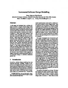
4.1. Organic Traffic Control Urban traffic networks are a promising applicationdomain for OC as traffic volumes rise constantly in cities and on highways worldwide, leading to serious congestion problems. Strategies like extending the existing road infrastructure are highly expensive and have mostly come to an end due to space limitations. Therefore, the most promising approach is to use the existing road networks more efficiently. Traffic lights are a vital factor in achieving efficient networks since control strategies have strong influence on the network-wide traffic situation. The environmental and economic importance of traffic control systems combined with the distributed nature of traffic nodes and their constantly changing traffic demands make traffic light control an ideal test case for OC approaches. In addition, urban traffic relies on coordination (e.g. in terms of progressive signal systems) and belongs to a superordinate network – the countrywide road network. Thus, the current status can be integrated into route recommendation mechanisms. The following part of this section describes the OTC system [45] as a case study for an OC application. As already mentioned, there are two possibilities to build OC systems: 1) develop new systems according to the OC paradigm or 2) equip existing systems with an external O/C component to allow for adaptive and robust behaviour. The OTC example follows the path of equipping an existing system with OC capabilities. Current installations in cities worldwide rely mainly on a so-called fixed-time controller. Here, engineers define traffic phases (in which several turning movements receive the right of way together, see Figure 10) and green durations for these phases. In addition, so-called interphases are defined, in which all traffic lights are switched to red to avoid accidents. Based on this phase system, the traffic light controller follows a simple time-dependent algorithm. It switches the traffic lights according to the phase plan and starts the cycle again after finishing the previous one. Figure 10 illustrates another important attribute of an intersection: detectors. These detectors are typically implemented as induction-loops in the street surface and are used to measure the current traffic situation for each turning movement (alternatively video-based sensors can be used for the same functionality). In the following, the six steps to develop a fully-fledged OC system as introduced in the context of the OC design process and the corresponding capabilities (see section 3) are described for OTC.
S. Tomforde and C. Müller-Schloer / Incremental Design of Adaptive Systems
Detector
Turning
Fig. 10. An idealised example intersection with detectors and turnings.
4.2. Design Decisions for Organic Traffic Control (1) Observation model: The first step in the OC process is to define the observation model which consists of the interface to monitor the SuOC and the situation description generated in each observation cycle. As the SuOC is an industry-standard fixed-time controller at an urban intersection, the interface allows for accessing all detector values available at the intersection. The situation description is then built upon this detector information – it measures the traffic flow (in vehicles hour ) for each turning movement. Furthermore, possibilities to predict future developments of the traffic situation can be taken into account [55], but all such augmenting factors are neglected for this example scenario in order to keep it simple. Consequently, the situation description for the example of Figure 10 consists of twelve real values (one statistically smoothed traffic flow value for each turning movement). (2) Configuration model: The second step consists of two parts: 1) defining a control-interface to access variable parameters and 2) building the controller to adapt these parameters at runtime. Again, all controllable parameters are assumed to be available though the interface (i.e. the system is OC-ready). The configuration space of the controller comprises the phase durations of all available phases within the cycle (without the interphases). Hence, the controller has to decide about the most promising phase durations for all turnings in each evaluation cycle. In addition, the step size for parameter adjustment has to be defined. For this scenario, one second as step size has been used as typical industry-standard phase controller accept posi-
13
tive integers as input (and hence a value of one is the fine-grainiest resolution). (3) Similarity metric: A rule-based selection of SuOC configurations has to discover the most promising rule in terms of a configuration set that is mostrelated to the currently observed situation. Therefore, the system has to be able to compare situation descriptions which is done based on a similarity metric. In the previous example, the situation description is a vector that consists of 12 real values (the turning flows) – in general, the n situation attributes form an n-dimensional hyper-rectangle. For such vector-based descriptions, the Euclidian distance is a standard tool to calculate similarities, which is used in OTC with the following modifications. The rules store intervals for each dimension rather than just a single point in the search space – while the input situation still consists of a point in the search space for each dimension. If the value of one dimension is contained in the interval of the other entity, the distance between them is zero. Otherwise, the distance is calculated in relation to the centre of the interval to avoid classifier conditions becoming too large. (4) Performance metric: The performance of an urban traffic control system is mostly measured in terms of waiting times – delays occurring at intersections should be minimised. Alternatives are e.g. minimising the number of stops per car when crossing the network (which is a network-wide figure) or minimising the economical effect of traffic (i.e. fuel consumption). The OTC system relies on a local detector-based measurement of traffic situations, which led to the decision of using the Level of Service (LoS) [41] as metric. The LoS value represents the flow-weighted delays at the intersection. Thus, OTC’s goal is to minimise this LoS value. (5) Validation method: In traffic engineering, two possibilities to implement the validation method at Layer 2 of the controller exist: 1) either the system can rely on simulations or 2) it can use approximation formulas (e.g. the Webster formula [63]) – both variants were investigated in OTC. The simulation-based approach relies on using the professional traffic simulation toolkit “Aimsun NG Professional” [5]. Each intersection controller possesses such an Aimsun simulator in combination with a simulation model reflecting its own topology and the phase plan. This model is configured using the traffic situation in terms of vehicles hour for each turning (extracted and randomised from the the situation description). Based on this simulation, an Evolutionary Algorithm [3] is used to find the best
14
S. Tomforde and C. Müller-Schloer / Incremental Design of Adaptive Systems
phase setup for a given situation. Alternatively, Webster’s formula can be used to approximate occurring delays, which replaces the simulation part. Both methods lead to similar results in most cases, but the formula is dramatically less computation-intensive (a detailed comparison of the advantages and disadvantages of both methods is given by Prothmann [44]). (6) Cooperation method: Nowadays, urban traffic control systems are much more than just choosing appropriate phase durations at isolated intersections. In contrast, network-wide optimisations for traffic streams are necessary as well as deriving status information (e.g. traffic jams or incidents) to proactively guide traffic. Therefore, different cooperation mechanisms have been developed for the OTC system, from which three examples are briefly introduced in the following: The Decentralised Progressive Signal Systems mechanism (DPSS) [59] establishes progressive signal systems (also called green waves) for the most heavilyloaded streams through the network using local decisions and one-hop communication only. The result is a coordination of a set of consecutive intersections in order to allow those drivers following the synchronised stream to travel through the network without stopping in font of red traffic lights. The Hierarchical Progressive Signal Systems (HPSS) mechanism [58] extends the DPSS method by an additional hierarchical component. While a completely decentralised coordination of intersections has many advantages (like reduced effort and cost compared to centralised systems), the restriction to local information can result in a suboptimal coordination. Therefore, the HPSS variant intervenes (if necessary) when the decentralised variant chooses the participating partners and rearranges partnerships. Afterwards, the DPSS algorithm is used to establish the synchronisation sequence. The Self-Organised Routing Mechanism transforms the OTC system from a standard traffic control system into a traffic management system [44,55] (in general, this means equipping the reactive control system for traffic lights with an integrated pro-active traffic guidance solution). To extend the OTC system with routing capabilities, it is assumed that signalised intersections are equipped with Variable Message Signs (VMS) at their approaches. For some prominent destinations, these VMSs provide the next turn of a recommended route to the drivers. The route recommendations are computed in response to the current traffic demands by adapted variants of standard network protocols: the Distance Vector Routing (see e.g. [54]) and
Link State Routing [36] protocols. The modified algorithms are executed locally at the intersections and use the VMS to inform drivers about the best route to their desired destination (turn right/left/straight ahead) and the predicted travel time when following the recommendation. Furthermore, extensions following the Internet’s Border Gateway protocol (see e.g. [34]) have been developed in order to keep the routing methods scalable. All these mechanisms assume a nearly perfect world: all intersection controllers provide all necessary information, information is undistorted, and no one tries to attack the system. These factors have to be considered when finally applying OTC to the real world. 4.3. Experimental Setup In a large part of current installations world-wide, traffic engineers develop time-dependent phase plans according to five classes: 1) week-start (i.e. Mondays), 2) week-days (i.e. normal Tuesdays), 3) last week-day (i.e. normal Fridays), 4) half-days (i.e. Saturdays), and 5) bank holidays (i.e. Sundays). Although the traffic profile during the course of the day is not exactly the same at each day, these five categories can be used to handle normal traffic patterns to a certain degree. Besides this regular traffic demand, local authorities have to handle non-regular events (like a football match) where the situation is hardly controllable with predefined static solutions developed at design time. The evaluation scenario for this article considers such a stadium event that generates abnormally high approaching and departing traffic. Further scenarios considering especially the normal course of the day as well as artificial settings can be found e.g. in [45]. Figure 11 depicts the simulated area located in Hannover, Germany. The signal plans and the traffic data are modelling a realistic setup and are based on information provided by the responsible authorities, the Landeshauptstadt Hannover (Fachbereich Tiefbau, Bereich Koordinierung und Verkehr) and the Verkehrsmanagementzentrale Niedersachsen (Region Hannover). The traffic data has been obtained from a census performed on May 09, 2009. The Aimsun models reflect the topologies of the intersections and roads as of spring 2010 – as the topology of the road network did not change within this time period, the combination of both is possible. The signalling of the traffic network surrounding the stadium is part of the overall traffic strategy for the urban area of Hannover. The intersection controllers are operated by seven differ-
S. Tomforde and C. Müller-Schloer / Incremental Design of Adaptive Systems
ent daytime-depending strategies: five according to the initially mentioned classification and two especially designed for stadium events. The latter two control strategies cover the approaching and departing traffic – in general, the former one optimises the network’s throughput on the main streets approaching the stadium, while the latter one provides traffic’s fast departure of the inner-city region. These two strategies serve as reference solution for the OTC solution. The simulation is performed – as mentioned before – using the traffic simulation toolkit Aimsun NG Professional [4,5]. Aimsun is an abbreviation for “Advanced Interactive Microscopic Simulator for Urban and Non-Urban Networks”.2 The simulator is an integrated transport modelling software, developed and marketed by the company Transport Simulation Systems (TSS) from Barcelona, Spain. In general, professional microscopic traffic simulators like Aimsun are simulation tools that aim at emulating the flow of individual vehicles through urban road networks as realistically as possible. In order to capture the full dynamics of time-dependent traffic phenomena, a large part of current microscopic traffic simulators rely on the theory of car-following, lane changing and gap acceptance models to model the particular behaviour of vehicles. Thereby, both global and local phenomena have influence on the individual vehicle’s behaviour – details on the theoretical parts are e.g. given in [22]. Traffic engineers of authorities make heavy use of these simulators in order to plan and optimise the traffic control strategies and topology of intersections in cities world-wide.
Intersection
Street
P
P P
Parking
P P
Stadium
P Map: © OpenStreetMap.org
Fig. 11. Simulated Stadium Area at Hannover, Germany.
2 See
http://www.aimsun.com for details.
15
4.4. Evaluation The evaluation compares the OTC-based control strategies to those actually being processed in cities. Therefore, the OTC system as developed using the OC design process is applied to a scenario in Hannover, Germany, where simulation models, traffic conditions for the complete days, and the actual traffic signalisation have been made available by local authorities. In the results, we distinguish between three different settings and compare their results: 1) OC-ready, 2) open O/C loop, and 3) closed O/C loop (cf. the segmentation of the design process in Section 3.3). Thereby, OC-ready means that the reference solution as developed by traffic engineers is used with the additional interfaces to observe and configure the SuOC. In this case, the O/C component does not intervene which leads to a static system behaviour and corresponds to the real implementation. Secondly, the open O/C loop works on a predefined set of rules that has been generated at design time. Therefore, we stored the situation descriptions of the simulations for the previous case in discrete time intervals of 5 simulated minutes and used the rule generation component at Layer 2 to discover the optimal parameter set for each of these situations. These rules were then available during the simulation. Finally, the closed O/C loop variant corresponds to the fully-fledged OC system that autonomously uses its Layer 2 component. In the context of this scenario, the cooperation methods have been disabled to demonstrate the positive effect already achieved by using the adaptation mechanism. As discussed when defining the OC capability 4 – the performance metric, OTC’s goal is to reduce waiting times occurring locally at the intersections. These waiting times are measured as averaged delays for all cars passing the intersection based on the queues of all incoming sections. The simulation-based evaluation allows for calculating a mapping between driving behaviour (driving, waiting, stopping, and accelerating) and the corresponding fuel consumption by taking realistic models into account [60,61]. In addition, the network-wide view allows for evaluating the averaged number of stops per vehicle. The following results are obtained as averages from five runs of the particular simulations with different random seeds. Initially, the evaluation investigates the impact of O/C decisions on the occurring delays within the investigated network. The delay (d) can be approximated by using the averaged travel times of all individuals through the network and defined by Equation 1.
16
S. Tomforde and C. Müller-Schloer / Incremental Design of Adaptive Systems
X
d =
∑ (i.endTime − i.startTime)/|X|
(1)
i=0
Figure 12 illustrates the achieved results. The abrupt drop after 3 hours of simulation time is caused by the setup of the simulation as the provided traffic data did not contain figures for the time interval between arrival and departure for the stadium event. Thus, only the arrival and the departure parts are simulated. The figure shows three curves for simulations with the same data. The OC-ready variant leads to an averaged delay of 174 sec per vehicle. The “open O/C loop” line represents a simulation of the OTC system with a static rule base. Obviously, the adaptive control strategy of OTC outperforms the reference solution (OC-ready) already with limited knowledge. The simulation using the open O/C loop variant resulted in an averaged delay of 97.1 sec per vehicle, which corresponds to a decrease of 44.2 % compared to the reference solution. Using the closed O/C loop variant, an additional benefit is visible as the simulation resulted in a decrease of 46.1 % (delay of 93.8 sec per vehicle) compared to the reference solution. 350 300
X
s =
(2)
∑ i.stops/|X|
i=0
Figure 13 depicts the corresponding results. The simulation of the OC-ready variant as reference solution results in 3.33 stops per vehicle on average, which is reduced by 23.3 % by the open O/C loop variant to 2.56 stops. Finally, the number of stops have been decreased by 25.0 % to 2.49 stops) due to OTC control (closed O/C loop). 6
5
4
3
2
1
250
Averaged delay
vehicles being simulated during the whole simulation period, |X| defines the size of this set and i is the variable for each individual. The function (i.stops) returns how often the particular vehicle i has to pause its travel through the network due to red traffic lights or traffic jams. Thereby, waiting in front of a traffic light for one phase equals one stop; waiting a second phase would increase the value to two stops. For instance, a car travelling through the network on a synchronised stream (w.r.t. Progressive Signal Systems) does not have to halt and therefore would have a stops-value of zero. In general, the number of stops increases with more signalised intersections to pass, a decreasing quality of the traffic light control strategy, and more load on the network, while it might decrease with more coordination for neighbouring traffic lights.
Number of stops per vehicle
Thereby, X represents the set of all vehicles being simulated during the whole simulation period, |X| defines the size of this set and i is the variable for each individual. The functions startTime and endTime return the simulation second where the particular individual entered the simulation or left it, respectively. Hence, the formula calculates the averaged travel time for all individuals during the simulated period of time.
0 0:00
0:30
1:00
1:30
2:00
2:30
3:00
3:30
4:00
4:30
5:00
200 150
OC-ready
Open loop
Closed loop
time
100 50 0 0:00
0:30
1:00
1:30
OC-ready
2:00
2:30
Open loop
3:00
3:30
Closed loop
4:00
4:30
5:00
time
Fig. 12. Occurring delays for the OC-ready, open and closed O/C loop variants.
A second major aspect is the number of stops at red traffic lights (or due to traffic jams). Equation 2 defines the metric formally. Again, X represents the set of all
Fig. 13. Network-wide number of stops per vehicle for the OC-ready, open and closed O/C loop variants.
The third part of the evaluation covers the environmental impact of traffic. An efficient control strategy for urban traffic lights can significantly decrease the pollution caused by traffic participants. Hence, the averaged fuel consumption is closely connected to delays and stops – the calculation of the corresponding values is already available within Aimsun. Equations 3 to 6 describe the model used by Aimsun, see [60]. A valida-
17
S. Tomforde and C. Müller-Schloer / Incremental Design of Adaptive Systems
0:30
1:00
1:30
2:00
2:30
3:00
3:30
4:00
4:30
5:00
Fuel consumption [l/100km]
time OC-ready
Open loop
Closed loop
Fig. 14. Fuel consumption per vehicle for the OC-ready, open and closed O/C loop variants.
curred situations again leads to a significantly decreasing demand for the generation of new rules. Using the rule base at the end of the closed O/C loop variant and simulating the scenario again leads to a demand of only one new rule per hour on average, which is nearly eliminated by repeating this process. Statistical variations, however, will in most cases result in new situations and the demand of new rules. Furthermore, the adaptation effort in terms of actually processed SuOC adaptations is an important issue. Figure 15 depicts the number of performed adaptations using the Layer 1 component with ongoing simulation duration. This value is again zero for the OC-ready variant, since it only observes the process and does not intervene. In contrast, the open O/C loop variant performed 503 adaptations on average, while the closed O/C loop variant performed 531 adaptations on average. Hence, the induced overhead by the additional organic control mechanism can already be handled by minor hardware demands and does not add noticeable overhead to the system.
Open O/C loop
Closed O/C loop
70 60 50 40
30 20 10
04:30 – 05:00
04:00 – 04:30
0
03:30 – 04:00
Figure 14 depicts the achieved result. Again, a significant reduction can be observed compared to the reference solution (OC-ready results in a consumption of 21.4 100l km ). Already the open O/C loop variant reduced the fuel consumption by 14.0 % to 18.4 100l km , while the closed O/C loop variant (19.9 % to 17.1 100l km ) resulted in a significantly better performance. Besides these traffic-based metrics, the performance of the O/C component and the corresponding effort for adaptation and rule generation is a major criterion in the analysis. Obviously, the effort for rule generation is zero (no generated rules) for the OC-ready variant. During runtime, it is also zero for the open O/C loop variant, since the effort took place at design time (here, 60 rules have been generated). In contrast, the closed O/C loop variant performed 90 rule generations on average during the five simulated hours. Further simulations showed that exposing the OTC system to the oc-
0:00
03:00 – 03:30
(6)
0
02:30 – 03:00
Fu4 = Fd × δt
5
02:00 – 02:30
Fu3 = (K1 × (1 + (v / 2 Vm )3 ) + K2 × V ) × δt (5)
10
01:30 – 02:00
(4)
15
01:00 – 01:30
Fu2 = (C1 + C2 × a × v) × δt
20
00:30 – 01:00
(3)
25
00:00 – 00:30
Fu1 = Fi × δt
30
Number of adaptations by Layer 1
tion of the equations has been exemplarily performed in [53]. Within the equations, Fu is the fuel consumption for every vehicle mode in (ml). Thereby, Fu1 defines the consumption if the vehicle is idling, Fu2 during acceleration, Fu3 when cruising, and Fu4 when decelerating. Furthermore, Fi defines the fuel consumption rate for idling vehicles in ml/sec, C1 and C2 are empirically derived constants to configure the fuel consumption rate for accelerating vehicles, K1 is a constant in l/100km (litre per 100 kilometre) for vehicles travelling at constant speed of 90 km/h, and K2 is similar to K1 but for a speed of 120 km/h. Additionally, Fd defines the fuel consumption rate for decelerating vehicles in ml/sec, a is the vehicle acceleration (in m/sec2 ), v is the vehicle’s speed (in m/sec), and δ t is the duration of the simulation time step (in sec).
time
Fig. 15. Performed adaptations by the O/C loop of Layer 1.
18
S. Tomforde and C. Müller-Schloer / Incremental Design of Adaptive Systems
5. Conclusion This article presented a novel meta-design process for the incremental development of adaptive systems. Based on the insight that standard design processes are not applicable to novel demands like moving parts of the design time effort to runtime and into the responsibility of organic and autonomic systems, the design process provides a modularised concept for building different stages of Organic Computing (OC) systems ranging from an OC-ready variant to an open Observer/Controller loop to a closed Observer/Controller variant. These three stages are characterised by an increasing degree of autonomy. Furthermore, this article presented traffic control as promising application for OC and as a testbed for large-scale Intelligent Environments (IEs). After applying the presented design concept and process to the traffic application, an experimental evaluation focusing on a realistic stadium event located in Hannover, Germany, has been presented. Here, an industry-standard traffic light controller has been augmented with the additional OC component in order to select and self-optimise appropriate configurations for the operated traffic lights. The evaluation compared the three different results of the OC design process and highlighted the potential benefit of applying the developed techniques to the operation of IEs. The efficiency of the traffic light control strategies has been improved by about 46 % in terms of occurring delays and by 25 % with respect to the number of stops per vehicle when travelling through the network. Finally, the intelligent traffic system has a significantly positive impact on the environment as the energy consumption has been decreased by about 4.3 100l km per vehicle. Current and future work follow two directions. First, the work on the architectural design and the corresponding design process continues by investigating possibilities to achieve a social behaviour between equal systems in order to collaboratively find global solutions based on local decisions. Thereby, further aspects like trust, security and appropriate interfaces for the interaction with human users will play an important role. Second, the traffic scenario is further investigated. As prototype for an IE, the traffic system will be adapted towards an active cooperation between infrastructure and drivers. Currently, a mostly reactive behaviour is considered as the system responds to what it observes via detectors and sensors. In contrast, communication between drivers and infrastruc-
ture can lead to more appropriate knowledge on the infrastructure-side (leading to a more sophisticated decision mechanism) and more user-centric recommendations at driver-side. Acknowledgements This work is a result from the Special Priority Programme “Organic Computing” which was supported by the Deutsche Forschungsgemeinschaft (DFG SPP 1183). In this context, we thank Holger Prothmann, Hartmut Schmeck (both Karlsruhe Institute of Technology, Germany), and Jürgen Branke (Warwick Business School, United Kingdom) for the productive atmosphere in the context of the Organic Traffic Control project which has been funded in the SPP. Furthermore, the authors are indebted to Markus Weinreich (Leibniz Universität Hannover, Germany) who participated in building the simulation models for the traffic scenario. References [1] M. Amoui, M. Derakhshanmanesh, J. Ebert, and L. Tahvildari. Achieving dynamic adaptation via management and interpretation of runtime models. Journal of Systems and Software – Special Issue on Self-Adaptive Systems, 85(12):2720 – 2737, 2012. [2] G. Anders, F. Siefert, J.-P. Steghöfer, and W. Reif. A Decentralized Multi-agent Algorithm for the Set Partitioning Problem. In Proceedings of PRIMA 2012: Principles and Practice of Multi-Agent Systems - 15th International Conference, pages 107–121, 2012. [3] T. Bäck and H.-P. Schwefel. Evolutionary Computing: An Overview. In Proceedings of IEEE Conference of Evolutionary Computing, pages 20 – 29, 1996. [4] J. Barceló. GETRAM/AIMSUN: A software environment for microscopic traffic analysis. In Proc. of the Workshop on Next Generation Models for Traffic Analysis, Monitoring and Management, held in Tucson (USA) in September 2001, 2001. [5] J. Barceló, E. Codina, J. Casas, J. Ferrer, and D. García. Microscopic traffic simulation: A tool for the design, analysis and evaluation of intelligent transport systems. Journal of Intelligent and Robotic Systems, 41(2–3):173–203, 2005. [6] V. Basili and J. Turner. Iterative Enhancement: A Practical Technique for Software Development. IEEE Trans. Software Eng., pages 265 – 273, Dec. 1976. [7] K. Beck. Extreme programming explained: embrace change. Addison-Wesley Longman Publishing Co., Boston, USA, 1999. [8] C. Becker, J. Hähner, and S. Tomforde. Flexibility in organic systems - remarks on mechanisms for adapting system goals at runtime. In ICINCO 2012 - Proceedings of the 9th International Conference on Informatics in Control, Automation and Robotics, pages 287–292, 2012.
S. Tomforde and C. Müller-Schloer / Incremental Design of Adaptive Systems [9] S. Beer. Diagnosing the System for Organizations. Managerial Cybernetics of Organization. John Wiley & Sons Publishers, 1994. [10] B. Boehm. A Spiral Model of Software Development and Enhancement. ACM SIGSOFT Software Engineering Notes, 11(4):14 – 24, 1986. [11] D. Britton. Formal verification of a secure network with endto-end encryption. In Proc. of IEEE Conf. Security and Privacy, pages 154 – 166, 1984. [12] E. Cakar, S. Tomforde, and C. Müller-Schloer. A role-based imitation algorithm for the optimisation in dynamic fitness landscapes. In IEEE Swarm Intelligence Symposium, 2011. SIS 2011, pages 139 – 146, 2011. [13] M. Callaghan, M. El-Gueddari, J. Harkin, T. M. McGinnity, and L. Maguire. Distributed Architecture for Adaptive Intelligent Environments. In Proceedings of IEEE/WIC/ACM International Conference on Web Intelligence (WI’04), pages 728 – 731, 2004. [14] M. H. Coen. Design principles for intelligent environments. In Proc. of the 15th national / 10th Conf. on Artificial Intelligence / Innovative Applications of Artificial Intelligence, AAAI ’98/IAAI ’98, pages 547–554, Menlo Park, CA, USA, 1998. American Association for Artificial Intelligence. [15] D. D’Angelo, C. Grenz, C. Kuntzsch, and M. Bogen. CamInSens – An Intelligent in-situ Security System for Public Spaces. In Proceedings of the 2012 International Conference on Security & Management (SAM), 2012, 16.-19. Jul, Las Vegas, USA. CSREA Press, 2012. [16] J. Dooley, M. Ball, and M. R. Al-Mulla. Beyond Four Walls: Towards Large-Scale Intelligent Environments. In Workshop Proceedings of the 8th International Conference on Intelligent Environments, volume 13 of Ambient Intelligence and Smart Environments, pages 158 – 168. IOS Press, 2012. [17] W. Ecker and M. Hofmeister. The design cube-a model for vhdl designflow representation. In Design Automation Conference, 1992., EURO-VHDL ’92, EURO-DAC ’92. European, pages 752 –757, sep 1992. [18] J. Erickson, K. Lyytinen, and K. Siau. Agile Modeling, Agile Software Development, and Extreme Programming: The State of Research. Journal of Database Management, 16(4):88 – 100, 2005. [19] D. Fisch, M. Jänicke, B. Sick, and C. Müller-Schloer. Quantitative Emergence – A Refined Approach Based on Divergence Measures. In Proceedings of IEEE Conference on SelfAdaptive and Self-Organising Systems (SASO10), pages 94– 103, Budapest, HU, 2010. [20] K. Forsberg and H. Mooz. The relationship of system engineering to the project cycle. In Proceedings of the First Annual Symposium of National Council on System Engineering, pages 57 – 65, 1991. [21] K. Forsberg and H. Mooz. Application of the Vee to Incremental and Evolutionary Development. In Proceedings of the National Council for Systems Engineering (NCOSE) Conference, pages 801 – 808, 1995. [22] J. F. Gabbard. Car-following models. In M. Papageorgiou, editor, Concise Encyclopedia of Traffic and Transportation Systems. Pergamon, Oxford, 1991. [23] D. Gajski, J. Peng, A. Gerstlauer, H. Yu, and D. Shin. System Design Methodology and Tools. Technical Report CECS03-02, Center for Embedded Computer Systems University of California, Irvine, 2003.
19
[24] D. I. Good. The Proof of a Distributed System in GYPSY. Technical Report 30, Institute for Computing Science, The University of Texas at Austin, 1982. [25] J. Hähner, S. Rudolph, S. Tomforde, D. Fisch, B. Sick, N. Kopal, and A. Wacker. A Concept for Securing CyberPhysical Systems with Organic Computing Techniques. In accepted for SAOS’13 Workshop held in conjunction with ARCS’13 in Prague, CZ from 18th to 22nd Feb. 2013, 2013. [26] J. Hartmann, W. Stechele, and E. Maehle. Self-adaptation for mobile robot algorithms using organic computing principles. In Proceedings of ARCS’13, pages 232–243, 2013. [27] W. Hasselbring. Top-down vs. bottom-up engineering of federated information systems. In EFIS’99, pages 131–138, 1999. [28] A. Hoffmann, F. Nafz, A. Schierl, H. Seebach, and W. Reif. Developing self-organizing robotic cells using organic computing principles. In Bio-Inspired Self-Organizing Robotic Systems, pages 253–273. 2011. [29] R. Jose, H. Rodrigues, and N. Otero. Ambient Intelligence: Beyond the Inspiring Vision. Journal of Universal Computer Science (J.UCS), 16(12):1480 – 1499, 2010. [30] B. Kempkes and F. Meyer auf der Heide. Local, Selforganizing Strategies for Robotic Formation Problems. In Revised Papers of: Algorithms for Sensor Systems - 7th International Symposium on Algorithms for Sensor Systems, Wireless Ad Hoc Networks and Autonomous Mobile Entities, pages 4– 12, 2011. [31] J. O. Kephart and D. M. Chess. The Vision of Autonomic Computing. IEEE Computer, 36(1):41–50, 2003. [32] L. Klejnowski, Y. Bernard, C. Müller-Schloer, and J. Hähner. Using trust to reduce wasteful computation in open desktop grid systems. In Proceedings of Tenth Annual International Conference on Privacy, Security and Trust, pages 250–255, 2012. [33] C. Larman and V. R. Basili. Iterative and incremental development: A brief history. Computer, 36:47–56, 2003. [34] J. Matthews. Computer Networking: Internet Protocols in Action. John Wiley & Sons, 1st edition, 2005. [35] S. McConnell. Rapid Development: Taming Wild Software Schedules. Microsoft Press Books, 1996. ISBN: ISBN 978-155615-900-8. [36] J. M. McQuillan, I. Richer, and E. C. Rosen. The new routing algorithm for the ARPANET. In C. Partridge, editor, Innovations in Internetworking, pages 119 – 127. Artech House, Inc., Norwood, MA, USA, 1988. [37] M. Mozer. An Intelligent Environment Must Be Adaptive. IEEE Intelligent Systems and their Applications, 14(2):11–13, 1999. [38] C. Müller-Schloer. Organic Computing: On the feasibility of controlled emergence. In CODES and ISSS 2004 Proceedings, September 8-10, 2004, pages 2–5. ACM Press., 2004. [39] C. Müller-Schloer, H. Schmeck, and T. Ungerer, editors. Organic Computing - A Paradigm Shift for Complex Systems. Autonomic Systems. Birkhäuser Verlag, 2011. [40] F. Nafz, H. Seebach, J.-P. Steghöfer, G. Anders, and W. Reif. Constraining Self-organisation Through Corridors of Correct Behaviour: The Restore Invariant Approach. In Organic Computing – A Paradigm Shift for Complex Systems, pages 79 – 93. Birkhäuser Verlag, 2011. [41] National Electrical Manufacturers Association. NEMA Standards Publication TS 2-2003 v02.06 – Traffic Controller Assemblies with NTCIP Requirements, 2003.
20
S. Tomforde and C. Müller-Schloer / Incremental Design of Adaptive Systems
[42] V. P. Office. Very high speed integrated circuits - vhsic - final program report 1980-1990. Technical report, Defense Technical Information Centers, 1990. [43] R. Pressman. Software Engineering: A Practitioner’s Approach. McGraw Hill, Boston, US, 2012. [44] H. Prothmann. Organic Traffic Control. PhD thesis, Karlsruhe Institute for Technology, AIFB Group, August 2011. [45] H. Prothmann, J. Branke, H. Schmeck, S. Tomforde, F. Rochner, J. Hähner, and C. Müller-Schloer. Organic Traffic Light Control for Urban Road Networks. International Journal of Autonomous and Adaptive Communications Systems, 2(3):203 – 225, 2009. [46] L. B. S. Raccoon. The chaos model and the chaos cycle. SIGSOFT Softw. Eng. Notes, 20(1):55–66, Jan. 1995. [47] F. Rammig. Systematischer Entwurf digitaler Systeme. B.G. Teuber, Stuttgart, DE, 1989. [48] U. Richter, M. Mnif, J. Branke, C. Müller-Schloer, and H. Schmeck. Towards a Generic Observer/Controller Architecture for Organic Computing. In Beiträge zur Jahrestagung der Gesellschaft für Informatik 2006, pages 112–119, 2006. [49] L. Romero, V. Zamudio, R. Baltazar, M. Sotelo, C. Lino, E. Mezura, and V. Callaghan. A Comparative Study of Intelligent Bio-inspired Algorithms Applied to Minimizing Cyclic Instability in Intelligent Environments. In Workshop Proc. of the 8th Int’l Conf. on Intelligent Environments, volume 13 of Ambient Intelligence and Smart Environments, pages 130 – 141. IOS Press, 2012. [50] W. W. Royce. The development of large software systems. Software Engineering Project Management, pages 1 – 9, 1988. [51] S. Rudolph. Konvergenz in Learning Classifier Systems. Thesis, Leibniz Universität Hannover, Institute for Systems Engineering, July 2010. [52] K. S. Shanmugan. Simulation and Implementation Tools for Communication and Signal Processing Systems. IEEE Communications Magazine, pages 42 – 53, 1994. [53] H. Swidan. Integrating AIMSUN Micro Simulation Model with Portable Emissions Measurement System (PEMS): Calibration and Validation Case Study. Master thesis, Graduate Faculty of North Carolina State University, 2011. [54] A. S. Tanenbaum. Computer Networks. Pearson Education, 4th edition, 2002.
[55] S. Tomforde. Runtime adaptation of technical systems: An architectural framework for self-configuration and selfimprovement at runtime. Südwestdeutscher Verlag für Hochschulschriften, 2012. ISBN: 978-3838131337. [56] S. Tomforde, B. Hurling, and J. Hähner. Distributed Network Protocol Parameter Adaptation in Mobile Ad-Hoc Networks. In Informatics in Control, Automation and Robotics, volume 89 of LNEE, pages 91 – 104. Springer, 2011. [57] S. Tomforde, H. Prothmann, J. Branke, J. Hähner, M. Mnif, C. Müller-Schloer, U. Richter, and H. Schmeck. Observation and Control of Organic Systems. In Organic Computing - A Paradigm Shift for Complex Systems, pages 325 – 338. Birkhäuser Verlag, 2011. [58] S. Tomforde, H. Prothmann, J. Branke, J. Hähner, C. MüllerSchloer, and H. Schmeck. Possibilities and limitations of decentralised traffic control systems. In 2010 IEEE World Congress on Computational Intelligence (IEEE WCCI 2010), pages 3298–3306. IEEE, 2010. [59] S. Tomforde, H. Prothmann, F. Rochner, J. Branke, J. Hähner, C. Müller-Schloer, and H. Schmeck. Decentralised Progressive Signal Systems for Organic Traffic Control. In S. Brueckner, P. Robertson, and U. Bellur, editors, Proceedings of the 2nd IEEE International Conference on Self-Adaption and SelfOrganization (SASO’08), pages 413–422. IEEE, 2008. [60] TSS – Transport Simulation Systems. Aimsun 5.1 microsimulator user’s manual, 2008. [61] Vehicle Certification Agency / UK Department for Transport. New car fuel consumption & emission figures, 2009. [62] T. Walther and R. P. Würtz. Learning to look at humans. In Organic Computing - A Paradigm Shift for Complex Systems, pages 309–322. 2011. [63] F. Webster. Traffic Signal Settings - Technical Paper No 39. Road Research Laboratory, London, UK, 1959. [64] M. Weiser. The computer for the 21st century. Scientific American, 265(3):66–75, September 1991. [65] S. W. Wilson. Classifier fitness based on accuracy. Evolutionary Computation, 3(2):149–175, 1995. [66] M. Wünsche, S. Mostaghim, H. Schmeck, T. Kautzmann, and M. Geimer. Organic Computing in Off-highway Machines. In Second International Workshop on Self-Organizing Architectures, pages 51–58. The International Conference on Autonomic Computing and Communications, ACM, Juni 2010.