Incremental Model Queries over EMF Models ? ´ G´abor Bergmann1 , Akos Horv´ath1 , Istv´an R´ath1 , D´aniel Varr´o1 , 2 ¨ os2 Andr´as Balogh , Zolt´an Balogh2 , and Andr´as Okr¨ 1
Budapest University of Technology and Economics, Department of Measurement and Information Systems, H-1117 Magyar tud´osok krt. 2, Budapest, Hungary fbergmann, ahorvath, rath,
[email protected] 2 OptxWare Research and Development LLC, H-1137 Katona J. u. 39. fandras.balogh, zoltan.balogh,
[email protected]
Abstract. Model-driven development tools built on industry standard platforms, such as the Eclipse Modeling Framework (EMF), heavily utilize model queries in various activities, including model transformation, well-formedness constraint validation and domain-specific model execution. As these queries are executed rather frequently in interactive modeling applications, they have a significant impact on the runtime performance of the tool, and also on the end user experience. However, due to their complexity, they can be time consuming to implement and optimize on a case-by-case basis. Consequently, there is a need for a model query framework that combines an easy-to-use and concise declarative query formalism with high runtime performance, so that even complex model queries can be executed instantaneously, even on large models found in industrial applications. In this paper, we propose a declarative EMF model query framework using the graph pattern formalism as the query specification language. These graph patterns describe the arrangement and properties of model elements that correspond to, e.g. a well-formedness constraint, or an application context of a model transformation rule. For improved runtime performance, we employ incremental pattern matching techniques: matches of patterns are stored and incrementally maintained upon model manipulation. As a result, query operations can be executed instantly, independently of the complexity of the constraint and the size of the model. We demonstrate our approach in an industrial (AUTOSAR) model validation context and compare it against other solutions.
Keywords: EMF, model query, incremental pattern matching, model validation
1
Introduction
As model management platforms are gaining more and more industrial attraction, the importance of automated model querying techniques is also increasing. Queries form ?
This work was partially supported by EU projects SENSORIA (IST-3-016004), SecureChange (ICT-FET-231101) and INDEXYS (ARTEMIS-2008-1-100021).
the underpinning of various technologies such as model transformation, code generation, domain specific behaviour simulation and model validation. In their most direct application, model queries may help find violations of well-formedness constraints of a domain-specific modeling language. Query evaluation entails a matching process, where an automated mechanism searches for model elements conforming to the structural pattern and attribute constraints imposed by the given query. The leading industrial modeling ecosystem, the Eclipse Modeling Framework (EMF [1]), provides different ways to query the contents of models. These approaches range from (1) the use of high-level declarative constraint languages (like OCL [2]) to (2) a dedicated query language [3] resembling SQL, or, in the most basic case, (3) manually programmed model traversal using the generic model manipulation API of EMF. However, industrial experience (including those of the authors) shows scalability problems of complex query evaluation over large EMF models, taken e.g. from the automotive domain. Current practice for improving performance is manual query optimization, which is time consuming to implement on a case-by-case basis. A promising way to address the performance problem is incremental pattern matching (INC) [4]. This technique relies on a cache which stores the results of a query explicitly. The result set is readily available from the cache at any time without additional search, and the cache is incrementally updated whenever (elementary or transactional) changes are made to the model. As results are stored, they can be retrieved in constant time, making query evaluation extremely fast. The trade-off is increased memory consumption, and increased update costs (due to continuous cache updates). In the current paper, we propose EMF-I NC Q UERY, a framework for defining declarative queries over EMF models, and executing them efficiently without manual coding. For the query language, we reuse the concepts of graph patterns (which is a key concept in many graph transformation tools) as a concise and easy way to specify complex structural model queries. High runtime performance is achieved by adapting incremental graph pattern matching techniques. The benefits of EMF-I NC Q UERY with respect to the state-of-the-art of querying EMF models include: (i) a significant performance boost when frequently querying complex structural patterns with a moderate amount of modifications in-between, (ii) efficient enumeration of all instances of a class regardless of location, and (iii) simple backwards navigation along references (these latter features address frequently encountered shortcomings of EMF’s programming interfaces). We demonstrate the advantages of our approach over existing EMF query alternatives by conducting measurements on a model validation case study in the context of AUTOSAR [5], an industrial standard design platform for automotive embedded systems. The paper is structured as follows: Section 2 introduces EMF and metamodeling, the mathematical formalism of graph patterns and AUTOSAR. Section 3 presents our declarative approach for queries over EMF. Section 4 elaborates the on-the-fly model validation case study in the domain of AUTOSAR, and Section 5 conducts benchmark measurements to assess the performance. A survey of similar tools and research is presented in Section 6. Finally, Section 7 summarizes the important points of the paper, draws conclusions and plots some future plans.
2
Background
In order to introduce our approach, this section briefly outlines the basics of the Eclipse Modeling Framework, graph patterns and gives a motivating example from the automotive domain based on the AUTOSAR framework. 2.1
Running Example: Constraint checking in AUTOSAR models
In the current paper, we will demonstrate our model query technique by checking wellformedness constraints over AUTOSAR models. AUTOSAR (Automotive Open System Architecture, [5]) is an open and standardized automotive software architecture, jointly developed by automobile manufacturers, suppliers and tool developers. The objectives of the AUTOSAR partnership include the implementation and standardization of basic system functions while providing a highly customizable platform which continues to encourage competition on innovative functions. The common standard should help the integration of functional modules from multiple suppliers and increase scalability to different vehicle and platform variants. It aims to be prepared for the upcoming technologies and to improve cost-efficiency without making any compromise with respect to quality. To improve quality and reliability of electrical/electronic systems, the validation of AUTOSAR models should be carried out in the early stages of the development process. The standard specifies a multitude of constraints, which should be satisfied to ensure proper functionality in this diverse environment. In this paper, we will present three of these constraints, and define validators for each of them. 2.2
EMF and Ecore Metamodeling
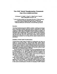
The Eclipse Modeling Framework (EMF [1]) provides automated code generation and toolARObject ing (e.g. notification, persistence, editor) for Java representation of models. EMF models Identifiable consist of an (acyclic) containment hierarchy +subPackage 0..* + shortName: int of model elements (EObjects) with references among each other; some references may only +element ARPackage be traversed by programs in one direction PackageableElement 0..* (unidirectional). Additionally, each object has a number of attributes (primitive data values). ARElement FibexElement Models are stored in EResources (e.g. files), and interrelated resources are grouped into EResourceSets. Fig. 1. AUTOSAR metamodel EMF uses Ecore metamodels to describe the abstract syntax of a modeling language. The main elements of Ecore are the following: EClass (represented graphically by a rectangle), EAttribute (entries in the rectangle) and EReference (depicted as edges). EClasses define the types of EObjects, enumerating EAttributes to specify attribute types of class instances and EReferences to define association types to other EObjects. Some EReferences additionally imply containment (graphically represented by a diamond). Unidirectional references are represented
by arrows. Both ends of an association may have a multiplicity constraint attached to them, which declares the number of objects that, at run-time, may participate in an association. The most typical multiplicity constraints are i) the at-most-one (0..1), and (ii) the arbitrary (denoted by *). Inheritance may be defined between classes (depicted by a hollow arrow), which means that the inherited class has all the properties its parent has, and its instances are also instances of the ancestor class, but it may further define some extra features. These concepts are illustrated by a simplified core part of the AUTOSAR [5] metamodel (Figure 1). Note that in all metamodel figures of the paper, only relevant attributes are depicted, but no elements are omitted from the inheritance hierarchy. Every object in AUTOSAR is inherited from the common ARObject class. If an element has to be identified, it has to inherit from the Identifiable class, and the shortName attribute has to be set. ARElement is a common base class for stand-alone elements, while specializations of FibexElement represent elementary building blocks within the FIBEX package. Instances of ARPackage class are arranged in a strict containment hierarchy by the subPackage association, and every PackageableElement can be aggregated by one of the ARPackages using the element association. 2.3
Graph patterns
Graph patterns [6] constitute an expressive formalism used for various purposes in Model Driven Development, such as defining declarative model transformation rules, defining the behavioral semantics of dynamic domain specific languages, or capturing general purpose model queries including model validation constraints. A graph pattern (GP) represents conditions (or constraints) that have to be fulfilled by a part of the instance model. A basic graph pattern consists of structural constraints prescribing the existence of nodes and edges of a Fig. 2. Graph Pattern for the given type. Languages usually include a way to ex- ISignal consistency check press attribute constraints. A negative application condition (NAC) defines cases when the original pattern is not valid (even if all other constraints are met), in form of a negative sub-pattern. With NACs nested in arbitrary depth, the expressive power of graph patterns is equivalent to first order logic [7]. A match of a graph pattern is a group of model elements that have the exact same configuration as the pattern, satisfying all the constraints (except for NACs, which must be made unsatisfiable). Figure 2 depicts a sample graph pattern CC ISignal. The structural part contains only a single node of type ISignal, but the NAC subpattern connects this node to a SystemSignal instance via an ISignal.systemSignal edge (note that some edges of that type may connect to a SystemSignalGroup instead of a SystemSignal, so the type assertion is relevant). Thus this graph pattern matches ISignal instances that are not connected to a SystemSignal. This graph pattern can be used as a declarative model query, in order
to validate the model against a structural well-formedness constraint that requires each ISignal to be connected to a SystemSignal. See Section 4 for further examples. Model queries with graph patterns. For readers with a strong EMF background, the idea of querying models by specifying graph patterns might not be straightforward. The key step in understanding the concept is that graph patterns declare what arrangement of elements is sought after, not how or where to find them. Each node in the pattern represents an EObject (EMF instance object), and the type of the node identifies the EClass of the object. This feature is useful to select only those model elements that conform to a certain type. Furthermore, the pattern nodes are connected by directed edges, annotated by an EReference type (or containment), to express how these elements reference each other. Finally, attribute constraints filtering and comparing the attributes of these elements can also be added.
3 3.1
Incremental Pattern matching over EMF models Benefits
The aim of the EMF-I NC Q UERY approach is to bring the benefits of graph pattern based declarative queries and incremental pattern matching to the EMF domain. The advantage of declarative query specification is that it achieves (efficient) pattern matching without time-consuming, manual coding effort compared to ad-hoc model traversal. While EMF-I NC Q UERY is not the only technology for defining declarative queries over EMF (EMF Query or MDT-OCL), it has a distinctive feature to offer: incremental pattern matching, with its special performance characteristics suitable for scenarios such as on-the-fly well-formedness checking. Additionally, some shortcomings of EMF are mitigated by capabilities of EMF-I NC Q UERY, such as cheap enumeration of all instances of a certain type regardless where they are located in the resource tree. Another such use is the navigation of EReferences in the opposite direction, without having to augment the metamodel with an EOpposite, which is problematic if the metamodel is fixed, or beyond the control of the developer.
3.2
Usage
EMF-I NC Q UERY provides an interface for each declared pattern for (i) retrieving all matches of the pattern, or (ii) retrieving only a restricted set of matches, by binding (a-priori fixing) the value of one or more pattern elements (parameters). In both cases, the query can be considered instantaneous, since the set of matches of the queried patterns (and certain subpatterns) are automatically cached, and remain available for immediate retrieval throughout the lifetime of the EMF ResourceSet. Even when the EMF model is modified, these caches are continuously and automatically kept up-to-date using the EMF Notification API. This maintenance happens without additional coding, and works regardless how the model was modified (graphical editor, programmatic manipulation, loading a new EMF resource, etc.).
3.3
Algorithm for Incremental Pattern Matching
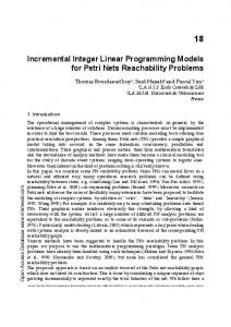
EMF-I NC Q UERY achieves incremental pattern matching by adapting the RETE algorithm, well-known in the field of rule-based systems. See [4] for the application of RETE on graph patterns, in a model transformation context, however, only core concepts could be adapted due to significant mismatch between VPM and EMF model management. The following paragraphs give an overview of the EMF specific behaviour of RETE. RETE network for graph pattern matching RETE-based pattern matching relies on a network of nodes storing partial matches of a graph pattern. A partial match enumerates those model elements which satisfy a subset of the constraints described by the graph pattern. In a relational database analogy, each node stores a view. Partial matches of a pattern are readily available at any time, and they will be incrementally updated whenever model changes occur. Input nodes serve as the underlying knowledge base representing a model. A RETE input node is introduced for each EClass, to contain the instances of the class (and subclasses), wrapped into unary tuples. The input nodes for EReferences and EAttributes contain all concrete occurrences of the structural feature as binary tuples (source, target). Finally, the EMF notion of containment is also represented by binary tuples in an input node, and usable in pattern definitions. At each intermediate node, set operations (e.g. filtering, projection, join, etc.) can be executed on the match sets stored at input nodes to compute the match set which is stored at the intermediate node. Finally, the match set for the entire pattern can be retrieved from the output production node. An important kind of intermediate node is the join node, which performs a natural join on its parent nodes in terms of relational algebra; whereas a anti-join node conFig. 3. RETE matcher of CC ISignal tains the set of tuples stored at the primary input which do not match any tuple from the secondary input. Figure 3 shows a simplified RETE network matcher built for the CC ISignal pattern (see Figure 2) illustrating the use of join nodes. It uses three input nodes, for instances of EClass ISignal, EClass SystemSignal and EReference ISignal.systemSignal, respectively. The first join node connects the latter two to find ISignal.systemSignal edges that actually end in objects of type SystemSignal. The second intermediate node performs an anti-join of the first input node and the previous join node, therefore containing instances of ISignal that are not connected to a SystemSignal via ISignal.systemSignal.
Fig. 4. Overview of the EMF-I NC Q UERY approach
This is exactly the match set of pattern CC ISignal, which is stored in the production node. Updates after model changes Upon creation, the RETE net is registered to receive notifications about all changes affecting an EMF ResourceSet, such as creation or deletion of model elements, via a service called EContentAdapter (or similar services provided by a transactional editing domain). Whenever receiving a notification, the input nodes of RETE are updated. This task is not always trivial: along containment edges, entire subtrees can be attached to an EMF Resource in one step, which requires careful traversal and multiple updates of input nodes. Each time input nodes receive notifications about an elementary model change, they release an update token on each of their outgoing edges. Such an update token represents changes in the partial matches stored by the RETE node. Positive update tokens reflect newly added tuples, and negative updates refer to tuples being removed from the set. Upon receiving an update token, a RETE node determines how the set of stored tuples will change, and release update tokens of its own to signal these changes to its child nodes. This way, the effects of an update will propagate through the network, eventually influencing the result sets stored in production nodes. 3.4
Architectural Overview of EMF-I NC Q UERY
Both the query language and the implementation of EMF-I NC Q UERY are adapted from the model transformation framework V IATRA 2 [8]. However, the role of V IATRA 2 is limited to the development phase, as the runtime module of EMF-I NC Q UERY is not
tied to it. Queries of EMF-I NC Q UERY can be defined by graph patterns in the transformation language [6] of V IATRA 2. A generator component can be invoked to translate them to the EMF-specific query formthat serves as the input for the EMF-based Pattern Matcher Engine. The latter is responsible for evaluating queries over EMF ResourceSets, and is intended to be invoked from arbitrary Java programs. Graph patterns suitable for the EMF conversion have to refer to the metamodel elements of the relevant EMF format. Therefore V IATRA 2 first needs to be aware of the EMF metamodel (the Ecore model), which can be ensured by importing it into V IA TRA 2’s (meta-)model representation, the VPM model space. As an additional benefit, the development of graph pattern based queries can be eased by taking advantage of the V IATRA 2 framework. The V IATRA 2 transformation interpreter shares identical functional behavior with EMF-I NC Q UERY. Therefore V IATRA 2 serves as a faithful prototyping environment for graph patterns, capable of experimenting on EMF instance models imported into its model space. See Figure 4 for a graphical overview of the various artifacts, software modules and their relations.
4
Benchmark case study
This section presents three well-formedness constraints from the AUTOSAR standard, which form the basis of our measurements in Section 5. 4.1
ISignal constraint check
The two metamodel elements for this constraint (SystemSignal and ISignal) are illustrated in Figure 5. A SystemSignal is the smallest unit of data (it is unique per System) and it is characterized by its length (in bits). (Also two optional elements can be specified, Datatypes and DataPrototype constants, but they are not used in this example.) An ISignal must be created for each SystemSignal (these will be the signals of the Interaction Layer). The graph pattern representation is explained in Section 2.3. 4.2
Signal group mapping constraint check
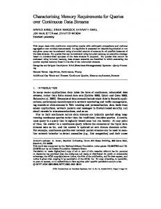
Related AUTOSAR elements ARElement +systemSignal FibexElement FibexElement The required metamodel eleAbstractSignal ISignal Pdu 0 ments for this constraint check +signal 0 are illustrated in Figure 5. A Identifiable IPdu SystemSignal ISignalToIPduMapping PDU (Protocol data unit) is +signalToPduMapping 0..* the smallest information which +systemSignal 0..* SystemSignalGroup SignalIPdu is delivered through a network layer. It is an abstract element in AUTOSAR, and has multiple Fig. 5. AUTOSAR metamodel (ISignal) different subtypes according to the available network layers. In this case study, we will only examine IPdus (Interaction Layer PDU), and more precisely SignalIPdus. These SignalIPdus used to transfer ISignals. The positions of these ISignals are defined by the ISignalToIPduMappings. The
ISignal can be a SystemSignal and a SystemSignalGroup as well. A signal group refers to a set of signals that must always be kept together to ensure the atomic transfer of the information in them. Constraint check for signal group mapping To ensure the atomic transfer of a SystemSignalGroup, we must pay attention to pack them properly into SignalIPdus. This means, if we refer to a SignalGroup from a SignalIPdu (with an ISignalToIPduMapping), then every Signal in it should be referenced as well from that IPdu. Note that an ISignalToIPduMapping references ISignals, but as every SystemSignal and SystemSignalGroup must have an ISignal it is not a problem. This constraint formulated in a graph pattern can be seen in Figure 6(a).
(a) Pattern to find invalid mappings
(b) Pattern to find invalid physical channels
Fig. 6. Consistency check patterns
4.3
Simple PhysicalChannel consistency check
Related AUTOSAR elements To demonstrate the chosen consistency check some additional AUTOSAR elements has to be described. These elements are illustrated by Figure 7. In AUTOSAR, ECU (ElecFibexElement Pdu tronic Control Unit) instances IPdu CommunicationCluster can communicate with each +iPdu 0 other through a communication +physicalChannel 0..* Identifiable +iPduTriggering Identifiable medium represented by a PhysSignalIPdu PhysicalChannel IPduTriggering 0..* icalChannel. Physical Channels +iSignalTriggering are aggregated by a Communi0..* +signalToPduMapping 0..* Identifiable +signal FibexElement +signal Identifiable cationCluster, which is the main ISignalTriggering ISignal ISignalToIPduMapping 0 0 element to describe the topological connection of communicating ECUs. A Physical ChanFig. 7. AUTOSAR metamodel (Channel) nel can contain ISignalTriggering and IPduTriggering elements. The IPduTriggering and ISignalTriggering describe the usage of IPdus and Signals on physical channels. ISignalTriggering defines the manner of
triggering of an ISignal on the channel, on which it is sent. IPduTriggering describes on which channel the IPdu is transmitted. Consistency check for physical channels The following constraint has to be satisfied for a physical channel: if a CH PhysicalChannel contains an IPDU SignalIPdu (through an IPduTriggering), then all of the S ISignal, contained by IPDU (through an ISignalToIPduMapping), must have a related STR ISignalTriggering in the CH channel. In other words the channel is invalid if there is at least one S ISignal that has no related ISignalTriggering in the channel. This informal definition is formalized in Figure 6(b) as a form of graph pattern. If the CC Channel(CH) pattern can be matched for a Physical channel CH, then it is considered to be invalid.
5
Benchmarking and Evaluation
5.1
Generating sample models for benchmarking
For a benchmarking evaluation, we designed a randomized model generator to create sample models of increasing size. For the three constraint cases, we used two different model families: (A) for ISignal and SSG and (B) for Channel. Both families contain an approximately equal number of valid and invalid model elements. The size of the sample model families ranges from a few thousand elements up to 600.000 (A) and 1.500.000 (B). A detailed description of the generation algorithm is in Appendix A.3 5.2
Benchmarking
The benchmark simulates the typical scenario of model validation. The user is working with a large model, the modifications are small and local, but the result of the validation needs to be computed as fast as possible. To emulate this, the benchmark sequence consists of the following sequence of operations: (1) First, the model is loaded into memory. In the case of EMF-I NC Q UERY, most of the overhead is expected to be registered in this phase, as the pattern matching cache needs to be constructed. Note however, that this is a one-time penalty, meaning that the cache will be maintained incrementally as long as the model is kept in memory. To highlight this effect, we recorded the times for the loading phase separately. (2) Next, in the first query phase, the entire matching set of the constraints is queried. This means that a complete validation is performed on the model, looking for all elements for which the constraint is violated. (3) After the first query, model manipulations are executed. These operations only affect a small fixed subset of elements, and change the constraint’s validity (Appendix A.2). (4) Finally, in the second query phase, the complete validation is performed again, to check the net effect of the manipulation operations on the model. 3
All appendices, along with the complete source code and all test cases can be found at http://viatra.inf.mit.bme.hu/models10
Benchmark implementations In addition to our EMF-I NC Q UERY-based implementation, we created two separate prototypes: a plain Java variant and an OCL variant that uses MDT-OCL [2]. The exact versions of EMF and MDT-OCL were 2.5.0 and 1.2.0 respectively, running on Eclipse Galileo SR1 20090920-1017. We ran the benchmarks on an Intel Core2 E8400-based PC clocked at 3.00GHz with 3.25GBs of RAM on Windows XP SP3 (32 bit), using the Sun JDK version 1.6.0 17 (with a maximum heap size of 1536 MBs). Execution times were recorded using the java.lang.System class, while memory usage data has been recorded in separate runs using the java.lang.Runtime class (with several garbage collector invocations to minimize the transient effects of Java memory management). The data shown in the results correspond to the averages of 10 runs each. All implementations share the same code for model manipulation (implementing the specification in Appendix A.2). They differ only in the query phases: – The EMF-I NC Q UERY variant uses our API for reading the matching set of the graph patterns corresponding to constraints. These operations are only dependent on the size of the graph pattern and the size of the matching set itself (this is empirically confirmed by the results, see Section 5.3). – The plain Java variant performs model traversal using the generated model API of EMF. This approach is not naive, but intuitively manually optimized based on the constraint itself (but not on the actual structure of the model [9]). – The OCL variant has been created by systematically mapping the contents of the graph patterns to OCL concepts, to ensure equivalence. We did not perform any OCL-specific optimization. The exact OCL expressions are in Appendix A.1. To ensure the correctness of the Java implementation, we created a set of small test models and verified the results manually. The rest of the implementations have been checked against the Java variant as the reference, by comparing the number of valid and invalid matches found in each round. 5.3
Analysis of the results
All relevant data recorded is shown in Figure 8. Overall, we have made the following observations: (1) As expected, query operations with EMF-I NC Q UERY are nearly instantaneous, they only grow to measurable values when the size of the matching set is large (in the case of large models). In contrast, query times show a polynomially increasing (with respect to model size) characteristic, both with the pure Java and the OCL variants. As intuitively expected, the optimized Java implementation outperforms OCL, but only by a constant multiplier. (As there was no observable difference between the two query phases, we show their sum in Figure 8). (2) Although not shown in Figure 8, the times for model manipulation operations were also measured for all variants, and found to be uniformly negligible. This is expected since very few elements are affected by these operations, therefore the update overhead induced by the RETE network is negligible. (3) The major overhead of EMF-I NC Q UERY is registered in the resource loading times
Fig. 8. Results overview
(shown in the Res column in Figure 8). It is important to note that the loading times for EMF itself is included in the values for EMF-I NC Q UERY. By looking at the values for loading times and their trends, it can be concluded that EMF-I NC Q UERY exhibits a linear time increase in both benchmark types, with a factor of approximately 2 compared to the pure EMF implementation. MDT-OCL does not cause a significant increase. (4) The memory overhead also grows linearly with the model size, but depends also on the complexity of the constraint itself. (More precisely, it depends on the structure of the underlying RETE network.) It has to be emphasized that in practical operations, the resource loading time increase is not important as it occurs only once during a model editing session. So, as long as there is enough memory, EMF-I NC Q UERY provides nearly instantaneous query performance, independently of the complexity of the query and the contents of the model. In certain cases, like for the SSG and ISignal benchmarks, EMF-I NC Q UERY is the only variant where the query can be executed in the acceptable time range for large models above 500000 elements, even when we take the combined times for resource loading and query execution into consideration. On the other hand, it has to be noted that this performance advantage is generally apparent for more complex queries, as indicated by the figures for the Channel benchmark, where the difference remains in the range of a few seconds even for large models. Overall, EMF-I NC Q UERY suits those application scenarios very well where there are complex queries, invoked many times, with relatively small model manipulations inbetween (like model validation for large, industrial models). Even though the memory consumption overhead is acceptable even for large models on today’s PCs, the techniques previously presented for V IATRA 2 to reduce the memory footprint by using a combination of pattern matcher implementations [9], are applicable here too (even if their implementation will on EMF-level require some future work).
6
Related Work
Model queries over EMF There are numerous technologies for providing declarative model queries over EMF. Here we give a brief summary of the mainstream techniques, none of which support incremental behavior. The project EMF Model Query [3] provides query primitives for selecting model elements that satisfy a set of conditions; these conditions range from type and attribute checks to enforcing similar condition checks on model elements reachable through references. The query formalism has several important restrictions: (i) it can only describe tree-like patterns (as opposed to graph patterns); (ii) nodes cannot be captured in variables to be referenced elsewhere in the query; and (iii) the query can only traverse unidirectional relations in their natural direction. Indeed, the expressive power of Model Query is intuitively similar to a formal logic belonging to a class of languages called description logics [10], and weaker than first order logic. Therefore more complex patterns involving circles of references or attribute comparisons between nodes cannot be detected by EMF Model Query without additional coding. EMF Search [11] is a framework for searching over EMF resources, with controllable scope, several extension facilities, and GUI integration. Unfortunately, only simple textual search (for model element name/label) is available by default; advanced search engines can be provided manually in a metamodel-specific way. EMF-I NC Q UERY is not the first tool to apply graph pattern based techniques to EMF [12, 13], but its incremental pattern matching feature is unique. Incremental OCL evaluation approaches OCL [14] is a standardized navigationbased query language, applicable over a range of modeling formalisms. Taking advantage of the expressive features and wide-spread adoption of OCL, the project MDT OCL [2] provides a powerful query interface that evaluates OCL expressions over EMF models. However, backwards navigation along references can still have low performance, and there is no support for incrementality. Cabot et al. [15] present an advanced three step optimization algorithm for incremental runtime validation of OCL constraints that ensures that constraints are reevaluated only if changes may induce their violation and only on elements that caused this violation. The approach uses promising optimizations, however, it works only on boolean constraints, therefore it is less expressive than our technique. An interesting model validator over UML models [16] incrementally re-evaluates constraint instances (defined in OCL or by an arbitrary validator program) whenever they are affected by changes. During evaluation of the constraint instance, each model access is recorded, triggering a re-evaluation when the recorded parts are changed. This is also an important weakness: the approach is only applicable in environments where read-only access to the model can be easily recorded, unlike EMF. Additionally, the approach is tailored for model validation, and only permits constraints that have a single free variable; therefore general-purpose model querying is not viable. Incremental Model Transformation approaches The model transformation tool TefKat includes an incremental transformation engine [17] that also achieves incremental pat-
tern matching over the factbase-like model representation of the system. The algorithm constructs and preserves a Prolog-like resolution tree for patterns, which is incrementally maintained upon model changes and pattern (rule) changes as well. As a new effort for the EMF-based model transformation framework ATL [18], incremental transformation execution is supported, including a version of incremental pattern matching that incrementally re-evaluates OCL expressions whose dependencies have been affected by the changes. The approach specifically focuses on transformations, and provides no incremental query interface as of now. VMTS [19] uses an off-line optimization technique to define (partially) overlapping graph patterns that can share result sets (with caching) during transformation execution. Compared to our approach, it focuses on simple caching of matching result with a small overhead rather than complete caching of patterns. Giese et al. [20] present a triple graph grammar (TGG) based model synchronization approach, which incrementally updates reference (correspondence) nodes of TGG rules, based on notifications triggered by modified model elements. Their approach share similarities with our RETE based algorithm, in terms of notification observing, however, it does not provide support for explicit querying of (triple) graph patterns.
7
Conclusion and Future Work
In this paper, we presented EMF-I NC Q UERY as the next evolutionary step in efficiently executing complex queries over EMF models by adapting on incremental graph pattern matching technology [4]. However, due to the significant mismatch between EMF and VPM model representation and management (unidirectionally navigable graph model stored in multiple files vs. bidirectionally navigable graph model with multiple typing stored in a single resource of the model space), we could actually reuse only the core concepts of RETE networks from our previous results [4, 9], and we had to build an incremental solution specific to EMF technology, which is the scope of our paper. The main lesson we learned from our experiments is that query evaluation should be tailored to the designated application scenario. We have specifically targeted EMFI NC Q UERY to support the fast evaluation of complex model queries. Due to the fundamentals of the technology, this works best in the case of interactive applications, where the model modification operations are small (with respect to the size of the entire model). Our results have confirmed the high performance of our implementation, but also the fact that the designer needs to keep the memory impact in mind. Practical applications of this technology include on-the-fly model validation, interactive execution of domain-specific languages, incremental model synchronization and incremental maintenance of (aggregated) model views for development tool environments. As future work, we intend to work on further automatic optimization, since, as with every declarative query formalism, there is always room for improvement. In the case of our RETE engine, this optimization targets the construction of the cache network, based on the pattern and the contents of the model itself. Additionally, we plan to work on integration with OCL as a query specification language. As it has been shown [21], a significant subsection of OCL can be mapped to the graph pattern formalism, especially if the pattern language is augmented with cardinality expressions.
References 1. The Eclipse Project: Eclipse Modeling Framework. http://www.eclipse.org/emf. 2. The Eclipse Project: MDT OCL. http://www.eclipse.org/modeling/mdt/?project= ocl. 3. The Eclipse Project: EMF Model Query. http://www.eclipse.org/modeling/emf/ ?project=query. ¨ os, A., R´ath, I., Varr´o, D., Varr´o, G.: Incremental pattern matching in the 4. Bergmann, G., Okr¨ VIATRA model transformation system. In Karsai, G., Taentzer, G., eds.: Graph and Model Transformation (GraMoT 2008), ACM (2008) 5. AUTOSAR Consortium: The AUTOSAR Standard. http://www.autosar.org/. 6. Varr´o, D., Balogh, A.: The Model Transformation Language of the VIATRA2 Framework. Science of Computer Programming 68(3) (October 2007) 214–234 7. Rensink, A.: Representing first-order logic using graphs. In: International Conference on Graph Transformations (ICGT), LNCS 3256, Springer (2004) 319–335 8. Fault Tolerant System Research Group at BME: VIATRA2 - VIsual Automated model TRAnsformations, URL: http://wiki.eclipse.org/VIATRA2. 9. Bergmann, G., Horv´ath, A., R´ath, I., Varr´o, D.: Efficient model transformations by combining pattern matching strategies. In: Proc. of ICMT’09, 2nd Intl. Conference on Model Transformation, Springer (2009) 10. Baader, F., Calvanese, D., McGuinness, D.L., Nardi, D., Patel-Schneider, P.F., eds.: The description logic handbook: theory, implementation, and applications. Cambridge University Press, New York, NY, USA (2003) 11. The Eclipse Project: EMFT Search. http://www.eclipse.org/modeling/emft/ ?project=search. 12. Biermann, E., Ermel, C., Taentzer, G.: Precise semantics of emf model transformations by graph transformation. In: MoDELS ’08: Proceedings of the 11th international conference on Model Driven Engineering Languages and Systems, Springer-Verlag (2008) 53–67 13. Giese, H., Hildebrandt, S., Seibel, A.: Improved flexibility and scalability by interpreting story diagrams. In Magaria, T., Padberg, J., Taentzer, G., eds.: Proceedings of GT-VMT 2009. Volume 18., Electronic Communications of the EASST (0 2009) 14. The Object Management Group: Object Constraint Language, v2.0. (May 2006) http: //www.omg.org/spec/OCL/2.0/. 15. Cabot, J., Teniente, E.: Incremental integrity checking of UML/OCL conceptual schemas. J. Syst. Softw. 82(9) (2009) 1459–1478 16. Groher, I., Reder, A., Egyed, A.: Incremental consistency checking of dynamic constraints. In: Fundamental Approaches to Software Engineering (FASE 2009). Volume 6013 of Lecture Notes in Computer Science., Springer (2010) 203–217 17. Hearnden, D., Lawley, M., Raymond, K.: Incremental model transformation for the evolution of model-driven systems. In Nierstrasz, O., Whittle, J., Harel, D., Reggio, G., eds.: Proc. of the 9th International Conference on Model Driven Engineering Languages and Systems. Volume 4199 of LNCS., Genova, Italy (2006) 321–335 18. Jouault, F., Tisi, M.: Towards incremental execution of ATL transformations. In: Proc. of ICMT’10, 3rd Intl. Conference on Model Transformation, Springer (2010) To appear. 19. M´esz´aros, T., et al.: Manual and automated performance optimization of model transformation systems. Software Tools for Technology Transfer (2010) To appear. 20. Giese, H., Wagner, R.: From model transformation to incremental bidirectional model synchronization. Software and Systems Modeling (SoSyM) 8(1) (3 2009) 21. Winkelmann, J., Taentzer, G., Ehrig, K., K¨uster, J.M.: Translation of restricted OCL constraints into graph constraints for generating meta model instances by graph grammars. Electron. Notes Theor. Comput. Sci. 211 (2008) 159–170
A A.1
Appendix OCL Representation of the ISignal, Channel and SSG AUTOSAR validation rules
The current appendix describes the OCL constraints as used in the Eclipse MDT-OCL framework to validate our benchmark case studies. – The OCL expression for the ISignal constraint context ISignal inv CC_ISignal : self. systemSignal ->isEmpty()
Listing 1.1. OCL invariants of the ISignal validation expression – The OCL expression for the Signal group mapping constraint (SSG) context ISignalToIPduMapping inv CC_SSG_1 : SystemSignalGroup . allInstances () -> exists( ssp | ssp . systemSignal -> exists( ssc | ssc =self. signal . systemSignal ) and self. eContainer ().oclAsType( SignalIPdu ). signalToPduMapping -> forAll( mp | mp . signal . systemSignal ssp ))
Listing 1.2. OCL invariants of the SSG validation expression – The OCl expression for the Simple Physical Channel consistency (Channel) context PhysicalChannel inv CC_Channel : self. iPduTriggering -> exists( itr | itr . iPdu .oclAsType( SignalIPdu ). signalToPduMapping -> exists( map |self. iSignalTriggering -> forAll( str | str . signal map . signal )))
Listing 1.3. OCL invariant of the Channel validation expression
A.2
Model Generation for the AUTOSAR case study
The current appendix summarizes how the models used in our benchmarks were generated along with the modification of the model for the constraint reevaluation. SSG and ISignal - Model Family A As a first step, the model generator creates an ARPackage element which contains all the generated models. Next, a constant number of SignalIpdus are created, with each containing a fixed number of blocks. These blocks, in turn, may contain four combinations of elements (the generator picks all combination types with equal probability): – In the first case, an ISignalToIPduMapping, which correctly refers an ISignal. This ISignal instance may, in approximately half of the overall cases, not contain a SystemSignal, which constitutes a match where the constraint of Section 4.1 is violated, however the constraint of Section 4.2 still holds. In the other half of the cases, this ISignal does have a SystemSignal, so it will correctly match against both the pattern shown in Section 4.1 and Section 4.2. All other cases only concern the constraint of Section 4.2, the pattern of Section 4.1 will match correctly against them.
– In the second case, the block contains two instances of ISignalToIPduMapping, which correspond to a correct match for Section 4.2 (a SystemSignalGroup containing a SystemSignal, both have an ISignal, referred by the ISignalToIPduMappings). The last two cases correspond to violated constraint matches for Section 4.2. – The third block type corresponds to the case where a ISignalToIPduMapping is created along with a SystemSignal and a SystemSignalGroup, but only the SystemSignal is connected to the mapping through an ISignal. – The third block type corresponds to the case where a ISignalToIPduMapping is created along with a SystemSignal and a SystemSignalGroup, but only the SystemSignalGroup is connected to the mapping through an ISignal. Channel consistency checking - Model Family B The model generator creates a CommunicationCluster instance, containing a fixed number of PhysicalChannels. Each of these refer to a random number of IPduTriggering elements containing a SignalIPdu. In turn, each of the SignalIPdus contain a random number of ISignalToIPduMappings containing an ISignal. Finally, the generator, in approximately half of the cases, creates a valid configuration by instantiating the ISignalTriggering element connecting the Channel and ISignal. In the other half of the cases, this element is omitted to make the Channel invalid in terms of the constraint described in Section 4.3. Model manipulation operations We define the model manipulation sequences as follows: – for the ISignal case (Section 4.1), the manipulator randomly picks 10 ISignal instances, deletes their corresponding systemSignal edge (if present). – for the SSG case (Section 4.2), the manipulator randomly picks 10 SignalIPdus, and deletes their first mapping (this may cause new invalid locations, or also valid ones). – for the Channel case (Section 4.3), the manipulator randomly picks 5 ISignals, and ”inverts” the validity of the match by either deleting the ISignalTriggering connection (if it was present) or creating a new one to the appropriate Channel (if not present).