Indirect Experience Recording and Display Technologies for Sensory Media Yasuyuki Yanagida2,1, Haruo Noma1,2, Shunsuke Yoshida1, Nobuji Tetsutani3,2, Kenichi Hosaka1,2, Norihiro Hagita2 1
2
3
ATR Media Information Science Laboratories ATR Intelligent Robotics & Communication Laboratories 2-2-2 Hikaridai, Keihanna Science City Kyoto 619-0288 Japan {yanagida | noma | shun | hosaka | hagita}@atr.jp
Abstract A method to record human experience related to sensory modalities other than vision and hearing is proposed. Our “record by re-experience” method does not require high-quality on-site sensing systems. The authoring and display systems for sensory media play very important roles in this approach. In this paper, research and development of display technologies for haptics, locomotion, and olfaction are introduced. Key words: Five Senses, Virtual Reality
1. Introduction “Ubiquitous Experience Media” is a concept that allows anybody to observe and share human experiences anytime, anywhere and in any way [1]. One of the key technologies for realizing this concept is to record one’s experience and let other people share it. We call such sharing of human experiences “co-experience.” Our goal is to explore and develop technological support for the observation and sharing of experiences and emotions. To provide a basis for this, we study ways to obtain and communicate sensory information and take an integrated approach to develop technologies for recognizing human action, reproducing experiences by using the five sensory modalities, and converting information from hetero-modal sensations to forms suitable for communication. In order to share human experiences, we have to solve a major problem: how to record one’s “experience.” So far we have studied ways to record one’s location, what one looks at, what one is doing, whom one is talking with, and so on [2]. Although these are important parts of our experience, they are not all of our experiences. How to record our total experience perceived through our five senses has not yet been clarified. In this paper, we discuss a methodology for recording people’s experience in an indirect manner, i.e., not by directly recording each stimulus with sensors but by
Tokyo Denki University Ishizaka, Hatoyama, Hiki, Saitama 350-0394 Japan
[email protected]
asking the user to remember the original experience and to reconfirm the experience by re-experiencing a simulated experience reproduced by using display systems. After introducing this method, several display technologies for haptic, locomotion, and olfactory interfaces are described.
2. Indirect Recording of Experiences Recording one’s experience is a challenging problem. A direct way to record one’s experience is to sense and record the incoming physical/chemical stimuli, when and where one has the experience. Here we call this “direct recording” or “stimulus recording.” We can apply this approach to visual and auditory sensations because welldeveloped sensing devices/systems are available for these sensory modalities. Color cameras can be regarded as generic, easy-to-use sensors for vision, and microphones are well-developed auditory sensors. With Artificial sensors
Signal processing
(Cameras, Microphones, etc.) Physical/chemical stimuli
Human sensory organ
Human brain
Subjective sensation
[Original experience] [Experience recording by re-experience]
Physical/chemical stimuli
Stimulus renderer
Human sensory organ
Subjective sensation
Result of direct recording: record of stimuli without subjective experience
Human memory
− +
Human brain
Sensory parameters Adjust Result of experience recording: output as parameters to produce stimuli
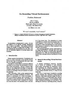
Figure 1: Concept of Experience Recording.
this method, the surrounding stimuli yielding one’s sensation are recorded, rather than the resulting subjective experience. Although the direct recording method is a reliable way to record one’s experience, this cannot be applied to sensory modalities for which appropriate sensors have not yet been developed. For example, there is no versatile haptic (combined force and tactile) sensor nor an odor sensor that can detect arbitrary (more than thousands of) kinds of human-detectable odorants. In order to record experiences related to sensor-unavailable kinds of sensory modalities (haptics, olfaction, etc.), we have to rely on our subjective experience and its memory in our brain. A straightforward method to solve this problem is, of course, to develop versatile, highperformance sensing devices and systems for all of our five senses. However, this might take a long time, partly because ways to efficiently code our sensations for some modalities have not yet been discovered. For example, there is no counterpart of “three primary colors” for olfaction, which means we cannot synthesize arbitrary smells easily. Hence, for now, we had better look for an alternative way to record one’s experience. Now let us consider the era before the invention of photography. At that time people managed to share their experiences by drawing pictures, which recall the event or scenery of the original experience. By analogy with this pre-photography co-experience with vision, we could somehow share the experience related to haptics, olfaction, and gustation by representing the subjective experience in each sensory modality. Figure 1 shows the concept of “experience recording.” The flow at the top of the figure indicates “direct recording,” without going through a human’s subjective sensation and memory. The rest of the figure shows the flow of indirect “experience recording,” by adjusting the parameters to yield simulated experience equivalent to the original one. With this approach we do not need explicit on-site sensing of the surrounding world when and where the user had the original experience. Instead, only authoring and display systems are needed. If it is difficult to compose a parametric authoring system, users can select a sample stimulus that yields the sensation closest to the one in their memory. A good example of this type is montage photo, which is used to compose a photo image of a human face by selecting sample images of the parts of the face. Thus it is very important to develop high-quality displays for haptics, olfaction and gustation, and so on. In the rest of this paper, we describe ongoing research and development at our laboratory on haptic, locomotion, and olfactory displays.
3. Haptic Displays 3.1 Force Display The desktop metaphor is commonly used for today’s computer-human interfaces, and it has been implemented as a Graphical User Interface (GUI) that displays the status solely by visual images. In order to introduce smooth migration from a conventional GUI to an audiovisual-haptic integrated authoring/display environment, we are trying to enhance the “Digital Desk” style interface by incorporating a force feedback function. The digital desk, which was proposed by Wellner in 1991 [3], broke through the boundaries between digitalized Graphical User Interface (GUI) desktops and our physical world. With digital desks, the user can seamlessly handle both digital and physical objects on the desk with a common standard. However, the typical digital desk provides the user only visual feedback as a projected image on an ordinary physical desk. In our research, we add a new function, namely, physical reaction from the digital desktop to the physical world (Figure 2). The Proactive Desk [4, 5] that we are developing is a solution for building a closed physical feedback loop within the concept of the digital desk. It is equipped with a unique 2-DOF (Degree of freedom) linear induction motor to realize this fourth function. Here, the user can handle objects with the feeling of haptic sensation as if handling real objects, and real objects on the desk can react in response to events. We built a unique 2-DOF Linear Induction Motor (LIM) into the Proactive Desk. The LIM that we use in the Proactive Desk corresponds to an AC motor, and is widely used in trains, elevators, conveyors, and so on. This device is adopted because the structure of the LIM is quite simple, it can generate huge amounts of power compared with other kinds of motors, and it can be easily designed with a long range of movement. The moving part of the LIM, which we call the “forcer,” is simply a conductive plate. In other words, by putting a small metal plate onto the user’s finger or some other object, the LIM can control the translational force (1) Immersive visual display Projector on the desk
Cameras and trackers
(2) Inputs by direct manipulation
Force feedback
Physical objects
(3) Registration of physical properties
Position control (4) Feedback using physical information
Figure 2: Appending force feedback function to a digital desk.
Travelling magnetic field B Eddy current i
Force F
Forcer
Inverter
Stator ( three pairs of coils ) 1:Coils generate travelling magnetic field B. 2:Avoiding the field, eddy current i is induced on the forcer. 3:The current i and magnetic field B generate force F on the forcer using Fleming’s left hand rule.
Figure 3: Operating principle of the linear induction motor. Figure 5: Proactive Desk. Left: overview, Upper-right: application running, Lower-right: paintbrush-like I/O device and mouse-compatible device.
Figure 4: The first trial 2-DOF LIM. generated onto it. With other linear motors, heavy permanent magnets or wired coils need to be attached to the user, which spoils the advantages of the digital desk in a similar way to the mechanical link approach. The operating principle of the LIM is illustrated in Figure 3. Our first trial 2-DOF LIM is shown in Figure 4. This prototype was designed based on Ohira’s bidirectional LIM [6]. Two sets of coils are placed in an orthogonal orientation inside the stator core, and each set of coils is driven individually by two AC inverters. Therefore, the motor can generate a traveling magnetic field of any power in any direction on the table. Figure 5 shows a photograph of the system. The stator of the 2-DOF LIM was mounted in the desk. An ordinary LCD projector was mounted over the LIM to provide a visual image on the LIM. Using the Proactive Desk as the user interface, the system needs to track the motion of the user’s hand holding the forcer without wires. We employed an optical tracking method using a 2-DOF Position Sensitive Detector (PSD) by Hamamatsu Photonics K.K. In the trial system, the PSD is mounted beside the projector and it tracks an LED marker on the forcer. It looks like a typical CCD camera, but the PSD provides continuous X and Y coordinate position data for the light spot on the forcer, and it features sufficiently high position resolution and high-speed response up to 20 kHz for fine force feedback. Having
Figure 6: A digital painting application with force feedback “Sumi-Nagashi” running on the Proactive Desk. realized a wireless forcer, we embedded an infrared LED, a controller, and a battery into the forcer as a target marker. We put a filter transparent to infrared light in front of the PSD lens and a filter transparent to visible light in front of the projector lens to cut off the light noise from the projector and other light noise, so that the projected light onto the desk does not interfere with position detection. We composed several applications to run on the Proactive Desk. One of these applications is called “Sumi-Nagashi” [7]. The purpose of this new art form is to add haptic sensations and corporeality to the world of digital painting. The installation “Sumi-Nagashi” allows painters (users) to experience a fluid pictorial installation, and to enjoy the process of creating a digital picture with visual and haptic sensations simultaneously. Figure 6 shows a scene of an interaction with the installation. is an The traditional form of sumi-nagashi ancient Japanese artistic technique, which means literally
“ink-floating.” Japanese sumi-ink thrown onto a still water surface makes dynamic patterns by disturbing the water’s surface, and the beauty of the constantly changing forms is captured instantaneously on Japanese paper. The origin of this art form is believed to be older than other similar techniques such as, for instance, European “marbling.” The most creativity-inspiring aspect of this new art form is its ability to enhance the experience and enjoyment of digital painting process for the user, while approaching the level of real interactive art. This installation lets the user perceive corporeally the virtual attributes of the digital color, which is generally perceived visually from the picture, through the sense of touch via the force feedback brush and canvas. This will give all painters an opportunity to realize how important the sense of touch is in the creative art process. In the application Sumi-Nagashi, the user is able to draw a picture naturally on a physical desk in a similar manner to conventional painting software. The desktop of the desk is actually a type of “digital canvas.” A picture generated by the computer as a result of an interaction with the user is projected onto the desktop by an overhead projector. The user holds a device shaped like a paintbrush and moves the device directly across the desktop as though it were a real brush. The path of the brush is colored by digital paints and the image on the desktop changes according to this new color information in real-time.
3.2 Vibrotactile Display Recently, researchers have been trying to expand the region of stimulation by tactile displays to the whole body. Some of these are suit-type displays that cover the whole body [8, 9], but existing systems only target discrete stimulation points, such as the shoulders, elbows, wrists, thighs, knees, and so on. These could be useful for some applications such as alert messages of simple collisions against objects or walls in virtual environments, but they are not sufficient to convey rich information by vibrotactile sensation. Another approach to body-oriented vibrotactile displays is to place many tactors at a certain region of the body at higher spatial density [10, 11]. This approach makes it possible to display rich information, but the target region is limited to one region of the body because it is technically difficult to place a large number of tactors over the whole body. Our interest lies in finding a way to balance these two approaches. We want to reduce the number of tactors as much as possible while still maintaining an acceptable level of expressive performance. We also limit ourselves to a low-cost solution for tactors: using vibrating motors. As a first step, we selected a well-studied task, tactile letter reading, to determine whether it is possible to achieve acceptable performance with an extremely
Figure7: Office chair with 3-by-3 tactor array for vibrotactile letter reading tasks reduced number of tactors. Specifically, we examined the ability to distinguish letters of the alphabet and numbers through vibrotactile stimuli provided by a 3-by3 tactor array. We applied a “tracing mode” to display letters, which has been proven to yield very good accuracy in tactile letter reading. This method makes use of the spatio-temporal characteristics of sequential strokes in writing letters rather than showing a dot matrix pattern of the entire letter at once. We conducted an experiment to determine how accurately people can recognize the displayed letters [12]. A 3-by-3 array of tactors was affixed to an office chair, with a spacing of 6 cm between the centers of each pair of neighboring tactors (Figure 7). The tactors used in this setup were DC motors with an eccentric mass. They are manufactured by Tokyo Parts Industrial Co., Ltd. (Model No. FM23A). To control the tactor array (described later), we used the TactaBoard system [13], developed at George Washington University. We had to provide a sequential pattern for each letter with a “tracing mode.” Because the tactor array size (3by-3) of our system is not sufficient to represent all of the alphanumeric characters by simultaneously activating the tactors composing the dot matrix pattern for each letter, this was not a simple tracing procedure. Nevertheless, we can still feel the direction and rough position of the stroke with a 3-by-3 tactor array. We decided to make use of the characteristic strokes composing each letter rather than exactly decomposing the pen trajectory into positions of the stimulation points. To do this, we made an interface program to map the hand-written stroke into a sequence of stimulation points. Figure 8 shows the mapping interface used to generate the sequence of stimulation points based on hand-written letters. With this utility, we can record the time and position of the mouse cursor and playback the recorded sequences. The partitioning scheme is not a
we can take advantage of the phenomenon called “tactile apparent movement” [15] or “sensory saltation” [16]. With this method, a single stroke is expressed by two (start and end) points, and it is driven so that the tactile apparent motion is perceived. Here, however, we face an undesirable characteristic in our system: the dull temporal response of vibrating motors, which is different from the quicker response of the sensors used in the previous research.
Figure 8: An interface to map mouse trajectory to stimulation points. simple grid; the central cell is in an octagon shape, so the diagonal strokes only cross the three diagonal cells. After generating the sequence of stimulation points for each letter, we extracted the information on the order of position and stroke continuity, discarding the duration of each stimulation point. This was done to avoid variation in pen speed in handwriting the letter, thus providing a uniform sequence of stimuli. We generated stimulation sequences for numbers and capital alphabet letters (10 digits plus 26 letters). The sequences for “O” and “0” (zero), and “Z” and “2” are identical, so there were 34 patterns in total. At the beginning of the experiment, the subject was asked to confirm the feeling of vibration stimuli and the location of tactors by activating each of nine tactors manually. Then, the experimental session was started. Each session was composed of 100 trials, which are categorized in three conditions: 38 trials with randomlyselected numeric characters, 52 trials with 2 sets of alphabet characters in random order, and 10 trials with randomly-selected alphanumeric (mixed) characters. The total ratio of correct letter recognition (accuracy) for all subjects was 87%. The values of accuracy were 87.6% for the set of numeric characters, 86.7% for the set of alphabet characters, and 86% for the set of alphanumeric (mixed) characters. The standard deviations among the 10 subjects for all trials, numeric, alphabetic, and mixed character sets were 10.4%, 14.1%, 10.1%, and 9.7%, respectively. There was no statistical significance between the numeric and alphabetic character sets (p > 0.1). Interestingly, the accuracy of letter reading was quite close to the correct identification rate of tactor position (84%) in our previous experiment [14]. This implies that further improving the accuracy of letter reading might be achieved by raising the performance of identifying the tactor’s position. One major problem with our method was that it took a relatively long time to show a letter (several seconds per letter). In order to reduce the stimulating time per letter,
In order to solve this issue, we are trying another type of tactor (voice-coil tactor) to invoke apparent motion. A detailed description of our study related to apparent movement is reported in [17].
4. Locomotion Interface In many applications of co-experience, such as travel reports, users need a good sensation of locomotion. We have been developing a novel locomotion interface system in collaboration with the University of Tsukuba. From the results of previous research on locomotion interfaces, we determined that an infinite surface is an ideal device to create the sense of walking. The easiest way to realize an infinite floor is to use a treadmill. However, it is difficult to realize omni-directional walking by using treadmills. Using a motion footpad for each foot is one alternative technique, since it has the ability to simulate omni-directional walking as well as walking on an uneven surface. The major limitation of this method is that extreme accuracy is required for the footpad to trace the walker. Actually, the walker has to be careful about erroneous tracing of the footpad. The CirculaFloor [18] is a new method that takes advantage of both the treadmill and footpad. It creates an infinite omni-directional surface by using a set of movable tiles. The combination of tiles provides a sufficient area for walking, and thus precision tracing of the foot position is not required. In order to achieve compact and scalable hardware, we designed a new configuration for a locomotion interface by using a set of omni-directional movable tiles. Each tile is equipped with a holonomic mechanism that achieves omni-directional motion. An infinite surface is simulated by the circulation of the movable tiles. The motion of the feet is measured by position sensors. The tile moves opposite to the measured direction of the walker so that the motion of the step is canceled. The position of the walker is fixed in the real world by this computer-controlled motion of the tiles. The circulation of the tiles has the ability to cancel the displacement of the walker in an arbitrary direction. Thus, the walker can freely change direction while walking. Examples of circulating the movable tiles are shown in Figure 9. There are several modes for controlling the circulation according to the walking direction. The full
Delivering scented air by vortex rings
Tracking nose direction
Camera
Air cannon
Aiming at the nose
Platform
Figure 11: Concept of projection-based olfactory display. systems could be an effective way to achieve a high level of presence.
Figure 9: Circulation examples of movable tiles
Figure 10: CurculaFloor: a novel configuration of a locomotion interface view of the system is shown in Figure 10. Technical details on CirculaFloor will be described in [19].
5. Olfactory Display Smells can often be a key to remembering one’s experience. VR systems so far have been developed to cover visual, auditory, and haptic sensations, so it is a natural progression to incorporate olfaction into VR systems. Incorporating olfactory interfaces in VR
Most attempts to realize an olfactory display have involved capturing and synthesizing the odor, but these processes still pose many challenging problems. These difficulties are mainly due to the mechanism of human olfaction, in which no set of so-called “primary odors” has yet been found. Instead, we focus on spatio-temporal control of odor rather than synthesizing odor itself. Many existing interactive olfactory displays simply diffuse the scent into the air, which does not allow the spatio-temporal control of olfaction. Recently, however, several researchers have developed olfactory displays that inject scented air under the nose through tubes. On the analogy of visual displays, these systems correspond to head-mounted displays (HMD). These yield a solid way to achieve spatio-temporal control of olfactory space, but they require the user to wear something on his or her face. We have proposed a novel configuration of an olfactory display [20] that can be considered a counterpart to projection-based visual displays. The key concept is to deliver scented air from a location near the user’s nose through free space. Users are not required to wear anything on the face, but it is still possible to switch among different scents within a short period and to limit the region in which the user can detect the scent. To implement this concept, we used an “air cannon” that generates a vortex ring of scented air (Figure 11). When we started this research, a preliminary experiment was conducted to examine this method’s ability to display scent to a restricted space. The results show that we could successfully display incense to the target user. Next, we constructed prototype systems. We could successfully bring the scented air to a specific user by tracking the nose position of the user and controlling the orientation of the air cannon to the user’s nose. We have made several prototype systems starting from a simple air cannon unit. From the second prototype
distance of vortex rings are mainly affected by the size of aperture and the profile of volume change but less affected by the total volume of the air cannon itself. A stepping motor was used to drive the crank for pushing the bellows.
Fresh air Air intake valve Shutters Tube
Push
Scented air
Figure 12: Scent switching mechanism.
This system is also equipped with a 2-DOF platform (custom made) and a CCD camera (Keyence CK-200, 0.25 mega pixels). The pumps and valves are controlled through controller units that communicate with the PC (DELL Workstation, Intel Xeon 2 GHz dual, RedHat Linux 8.0) through an RS-232C communication line. A full view of the system is shown in Figure 13. We arranged two kinds of fragrance (orange and mint) generated by a scent diffuser (“Hippocampe,” of Jacques G. Paltz) for each, as well as an offensive smell (ammonia: simply stored in a container). We succeeded in delivering different smells with each shot of the air cannon. Most users could tell the differences between these odors, and they showed distinct reactions when we shot ammonia.
6. Conclusion
Figure 13: Projection-based olfactory display using an air cannon system, we applied a vision-based nose tracker [21], together with a 2-DOF platform carrying the air cannon. We incorporated a scent switching mechanism in the latest prototype system [22]. In our previous prototypes, scented air was injected into the body of the air cannon in order to steadily compose the vortex ring with scented air. With this configuration, however, we could present only a single kind of scent to the user because some portion of the scented air diffused into the air cannon body, where it was difficult to eliminate before presenting the next injected scent. To solve this problem, we attached a short cylinder with the same diameter as the aperture of the air cannon and equipped with mechanical shutters at both ends (Figure 12). There are five holes on the surface of the cylinder for air-intake and evacuation. A tube is connected to each hole, through an air valve, to a pump. We used 4 holes for scent injection and one for evacuation. There is also a valve on the body of the air cannon for intake of fresh (non-scented) air. The body of the air cannon is composed of a bellows to generate a larger volume change over the cannon’s entire size. This design is based on our experimental study on the air cannon [23], showing that the maximum transfer
A method to record experience by reliving simulated experience is proposed. This method can be called the “recording by re-experience” approach for sensory modalities for which the performance of sensing systems has not yet reached a sufficient level, e.g. haptic, olfactory. With this approach, display devices and systems are the key to achieving a usable “experience recording” system. Also, useful authoring applications are essential elements to compose the entire system. Our future work includes making useful authoring applications for haptic and olfactory sensations.
Acknowledgments We would like to thank our collaborators: Prof. Jun Kurumisawa of Chiba University of Commerce, Prof. Robert W. Lindeman of George Washington University, Prof. Yuichiro Kume of Tokyo Polytechnic University, Prof. Hiroo Iwata of University of Tsukuba, and Prof. Akira Tomono of Tokai University. This research was supported by the National Institute of Information and Communications Technology.
References 1. N. Hagita, “Introduction to Ubiquitous Experience Media,” ATR Workshop on Ubiquitous Experience Media, URL http://www.mis.atr.jp/uem2003/, 2003. 2. N. Tetsutani, “Research on Sensory Media : Sensing and Display,” ATR Workshop on Ubiquitous Experience Media, URL http://www.mis.atr.jp/uem2003/, 2003. 3. P. Wellner, “The DigitalDesk Calculator: Tangible manipulation on a desk top display,” Proc. of ACM
Symposium on User Interface Software and Technology 1991, pp. 27–34, 1991. 4. H. Noma, N. Tetsutani, and Y. Yanagida, “The Proactive Desk: A New Force Display System for a Digital Desk Using 2-DOF Linear Induction Motor,” Proc. of IEEE Virtual Reality 2003, pp. 217–224, 2003. 5. H. Noma, S. Yoshia, Y. Yanagida, and N. Tetsutani, “The Proactive Desk : A New Haptic Display System for a Digital Desk Using a 2-DOF Linear Induction Motor,” Presence, Vol. 13, No. 2, pp. 146-163, 2004. 6. Y. Ohira and T. Kawanishi, “Experimental Consideration of the Bidirectional Linear Induction Motor,” Journal of the Society of Instrument and Control Engineers, Vol. 19, No. 2, pp. 74–79, 1983 (in Japanese). 7. S. Yoshida, J. Kurumisawa, H. Noma, N. Tetsutani, and K. Hosaka, “Sumi-Nagashi: Creation of New Style Media Art with Haptic Digital Colors,” in Proc. of ACM Multimedia 2004. 8. H. Yano, T. Ogi, and M. Hirose, “Development of Haptic Suit for Whole Human Body Using Vibrators,” Trans. of the Virtual Reality Society of Japan, Vol. 3, No. 3, pp. 141–148, 1998 (in Japanese). 9. E. Gunther, G. Davenport and S. O’Modhrain, “Cutaneous Grooves: Composing for the Sense of Touch,” Proc. of 2002 Conference on New Interfaces for Musical Expression (NIME-02), pp. 37–42, 2002. 10. A. H. Rupert, “An Instrumentation Solution for Reducing Spatial Disorientation Mishaps,” IEEE Engineering in Medicine and Biology Magazine, Vol. 19, No. 2, pp. 71–80, 2000. 11. U. Yang, Y. Jan, and G. J. Kim, “Designing a VibroTactile Wear for Close Range Interaction for VRbased Motion Training,” Proc. ICAT 2002, pp. 4–9, 2002. 12. Y. Yanagida, M. Kakita, R. W. Lindeman, Y. Kume, and N. Tetsutani, “Vibrotactile Letter Reading Using a Low-Resolution Tactor Array,” Proc. of 12th International Symposium on Haptic Interfaces for Virtual Environment and Teleoperator Systems, pp. 400–406, 2004.
13. R. W. Lindeman and J. R. Cutler, “Controller Design for a Wearable, Near-Field Haptic Display,” Proc. of 11th International Symposium on Haptic Interfaces for Virtual Environment and Teleoperator Systems, pp. 397–403, 2003. 14. R. W. Lindeman and Y. Yanagida, “Empirical Studies for Effective Near-Field Haptics in virtual Environments,” Proc. of IEEE Virtual Reality 2003, pp. 287–288, 2003. 15. J. H. Kirman, “Tactile apparent movement: The effects of interstimulus onset interval and stimulus duration,” Perception & Psychophysics, Vol. 15, No. 1, pp. 1–6, 1974. 16. H. Tan, A. Lim, and R. Traylor, “A Psychophysical Study of Sensory Saltation with an Open Response Paradigm,” Proc. of 9th International Symposium on Haptic Interfaces for Virtual Environment and Teleoperator Systems, ASME Dynamic Systems and Control Division, Vol. 69-2, pp. 1109–1115, 2000. 17. M. Niwa, Y. Yanagida, H. Noma, K. Hosaka, and Y. Kume, “Vibrotactile Apparent Movement by DC Motors and Voice-coil Tactors,” in Proc. of ICAT 2004. 18. H. Iwata, H. Fukushima, H. Noma, and H. Yano, “CirculaFloor,” ACM SIGGRAPH 2004 Emerging Technologies, 2004. 19. H. Iwata, H. Yano, H. Fukushima, and H. Noma, “Development of a New Locomotion Interface CirculaFloor,” IEEE Computer Graphics & Applications, to appear in January 2005. 20. Y. Yanagida, H. Noma, A. Tomono, and N. Tetsutani, “An Unencumbering, Localized Olfactory Display,” ACM CHI2003 Extended Abstracts, pp. 988–989, 2003. 21. S. Kawato and N. Tetsutani, “Detection and Tracking of Eyes for Gaze-camera Control,” Proc. of VI2002, pp. 348–353, 2002. 22. Y. Yanagida, S. Kawato, H. Noma, A. Tomono, and N. Tetsutani, “Projection-Based Olfactory Display with Nose Tracking,” Proc. of IEEE Virtual Reality 2004, pp. 43–50, 2004. 23. J. Yu, Y. Yanagida, S. Kawato, and N. Tetsutani: “Air Cannon Design for Projection-Based Olfactory Display,” Proc. of ICAT 2003, pp. 136–142, 2003.