in unsteady flow. Keywords: Tidal turbine, Added Mass, Oscillatory Flow,. Waves. Nomenclature a. = axial induction factor. Ëa. = time derivative of axial induction ...
Inertia Effects on Horizontal Axis Tidal-Stream Turbines J.I. Whelan, J.M.R. Graham, J. Peir´o1 1 Department
of Aeronautics, Imperial College, London, SW7 2AZ, UK
Abstract
V = volume x = axial position z = depth ζ = Surface elevation of Seiche Wave Λ = tip speed ratio µ = Current number ρ = fluid density τ = non-dimensional time ω = frequency of oscillation Abbreviations Fr = Froude number, √Ugz . KC = Keulegan-Carpenter number
This work studies the effects of inertia (added mass) on horizontal axis tidal-stream turbines in unsteady flow. Experiments have been conducted using both an instrumented model rotor and a porous disc as an analogue subjected to unsteady planar (axial) motion in a steady flow water flume. Measurements are presented of the instantaneous axial thrust of the rotor operating at constant torque. Drag and inertia coefficients are calculated for the rotor over a range amplitude parameters (KeuleganCarpenter number) and rotor operating points (tip speed ratio). These results are compared to Morison’s equation for axial force on a body in unsteady flow and also to model predicting dynamic inflow effects. The results provide an insight into the axial added mass and wake effects and they will help our conceptual understanding of these phenomena which overlap, for a rotor operating in unsteady flow.
1
True added mass effects are insignificant on wind turbines, except at very high frequencies, but because of the much lower mass ratios, they can be very significant for turbines operating in unsteady water flows. The types of unsteadiness considered here are assumed to arise from incident free surface waves on moderately shallow tidal flows, from large scale turbulent eddies, and whenever large rotor accelerations occur. Likely sites for tidal stream turbines will be subject to strong tidal flows (e.g. peak velocities of order 2 m s−1 and above) and will usually involve comparatively shallow flow either around a headland or in a narrow facing the open sea (Carbon Trust [1]). Such sites are exposed to both sea waves and (it is believed) considerable turbulence due to the rough sea-bed and channel walls. Unsteady flow effects, such as passing waves, cause an abrupt change in flow speed at the plane of the turbine which generates associated changes in loading. The wake of the rotor does not respond immediately, based on flow conditions and device scales detailed in McCann et al. [2], a typical time scale, D/U, for a tidal turbine being of the order 5 to 10 s. This lag in the response of the wake is known as dynamic inflow and has been successfully modelled in the wind and helicopter industries using quasi-steady models such as that developed by Pitt and Peters [3]. This model introduces the time lag by giving the rotor an additional added mass equivalent to 67% of the volume of the fluid in a sphere with the same diameter as the rotor. As part of work on wind turbines, Snel and Schepers [4] compared dynamic inflow models to full scale measurements for a rotor experiencing abrupt changes in pitch angle. The dynamic inflow models predicted a significant overshoot of load-
Keywords: Tidal turbine, Added Mass, Oscillatory Flow, Waves
Nomenclature a a˙ A As c CD C′ D CM D FX Hs k l R1 R2 t T u′ u u˙ u˜ us U
= = = = = = = = = = = = = = = = = = = = = = =
Introduction
axial induction factor time derivative of axial induction factor facing area Amplitude of Seiche wave √ gz coefficient of drag coefficient of oscillatory drag coefficient of mass diameter of rotor or porous plate axial force on the rotor significant wave height resistance coefficient effective length of the flume Radius of outer section Radius of inner section time time period of oscillation velocity of carriage velocity at the rotor plane acceleration of rotor maximum oscillatory velocity velocity of Seiche Wave upstream mean velocity
c Proceedings of the 8th European Wave and Tidal Energy
Conference, Uppsala, Sweden, 2009
586 1
Carpenter number
ing due to a step change in pitch angle compared with quasi-steady predictions. This overshoot was confirmed by their measurements. A rotor subjected to coherent wind gusts (abrupt changes in axial velocity) was also simulated using the same dynamic inflow models, and the effect of this was predicted to be much smaller than in the case of the pitch transients. An initial experimental investigation into the size of the effect of dynamic inflow due to changes in axial velocity in water is attempted here. As a first step to approximate the effects of waves, a model turbine is subject to planar oscillatory motion. An experiment is also conducted with a porous disc which provides an analogy for the axial resistance of a rotor. This paper presents the result of these experiments.
2
KC =
u’(t) Motorised carriage
Towing track
Experiments were carried out in the water flume in Imperial College, which has a working section 9 m long, 0.6 m wide and depth z = 0.62 m. The flume was run at flow speed, U, of up to 0.3 m s−1 , corresponding to a Froude number, Fr, of 0.12 at full depth. Instantaneous measurements of axial force were made on both a porous disc with a resistance coefficient, k, of 2, with D = 0.4 m and on a rotor with a D = 0.56 m. A porous disc is a physical example of an actuator disc often used to simulate a turbine in small scale laboratory experiments. Details of both the porous plate and the rotor can be found in Whelan et al. [5]. Both the porous plate and rotor were mounted from above the flume from a motorised carriage which was oscillated back and forth according to a known time history, u′ (t), leading to an instantaneous velocity at the turbine plane of u(t) = U + u (t).
(3)
McCann et al. [2] suggest an extreme wave case (a 10year wave event) of significant wave height, Hs = 9 m and time period, T = 9 s based on the EMEC site where the maximum flow speed, U = 4m s−1 . Such an extreme wave has the potential to induce a maximum oscillatory velocity, u, ˜ of order 3 s−1 at the free surface. Based on the suggested rotor diameter, D = 15 m the KC number is equal 1.8, which is at the upper end of the range of KC investigated. For the majority of operation however, even in a turbulent sea-state the KC number representing the amplitude of the oscillation approximately 0.5.
Experimental procedure
′
uT ˜ . D
1111111111111111111111111111111111111111 0000000000000000000000000000000000000000 0000000000000000000000000000000000000000 1111111111111111111111111111111111111111 0000000000000000000000000000000000000000 1111111111111111111111111111111111111111 0000000000000000000000000000000000000000 1111111111111111111111111111111111111111
Free surface Support shaft Rotor
z
U Instrumented hub
11111111111111111111111111111111111111111 00000000000000000000000000000000000000000 00000000000000000000000000000000000000000 11111111111111111111111111111111111111111
Flume bottom
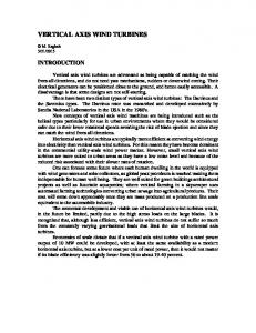
Figure 1: A schematic of a sideview of the experimental layout
(1) 0.04 Velocity (m/s)
A schematic drawing of a sideview of the experimental set-up of the rotor experiments is shown in Fig. 1. The porous plate was mounted on a similar support shaft. Measurements of axial force were taken using a strain gauge arrangement on the supporting strut. A constant torque was applied to the rotor shaft inside a waterproofed hub using an electromagnetic brake. It was not possible to oscillate the carriage sinusoidally due to restrictions in the carriage damping system, therefore the time histories of velocity approximate displaced sinusoids with a hesitation as the direction is reversed. However the velocity time history was acquired at the same time as the measurement of axial thrust so their relative phase was known. The acceleration, u(t) ˙ of the carriage was calculated from the velocity time history. Typical time histories (both velocity and acceleration) of the carriage are shown in Fig. 2, where the non-dimensional time is 2π t τ= . (2) T A series of experiments were conducted over a range of amplitude parameters defined by the Keulegan-
0.02 0 −0.02 −0.04
0
5
10
15
20
25
30
0
5
10 15 20 Non−dimensional time τ
25
30
2
Acceleration (m/s )
0.02 0.01 0 −0.01 −0.02
Figure 2: Typical velocity and acceleration time history.
3
Modelling of axial force
The most established model for axial force on bodies generating axial resistance in oscillatory flow is Morison’s equation, in which the force FX in the flow direction on the device (area A, volume V ) subject to velocity
587 2
U(t) is: 1 FX (t) = ρ u(t)|u(t)|ACD + ρ u(t)VC ˙ M. 2
was placed 1m upstream of the rotor plane (so as to be out of the interference of the rotor) and a time history of the surface elevation was recorded relative to the the axial force and carriage movement measurements. A typical correction is shown in Fig. 4. The surface elevation is approximated using Eq.(7). The corresponding axial velocity calculated at the same axial position using Eq.(8) is then added to the velocity of the carriage to give the corrected velocity. It can be seen that the correction to the velocity introduces an asymmetry in the cycle. After applying the correction this asymmetry is more consistent with the asymmetry in the force signal. The correction could only be applied accurately when the input oscillation of the carriage had a time period within a reasonable range of the fundamental period of the Seiche wave. This restricted the experimental tests to a minimum time period of 10s. In order to cover both the low and high KC ranges, two different oscillatory current numbers, u˜ µ= , (9) U were used in the experiments. For the lower KC range µ = 0.08 whilst for the higher range µ = 0.22.
(4)
A is the facing area π D2 /4 and it is usual for disc-like bodies such a rotor to take V as the volume of the circumscribing sphere π D3 /6. It is possible to determine drag and inertia coefficients in Eq.(4) for any periodic flow by multiplying Eq.(4) by u(t) and u(t) ˙ and averaging over an exact number of cycles as detailed by Bearman et al. [6]. This is true irrespective of the profile of u(t) because u(t) and u(t) ˙ are 90◦ out of phase in the mean. Thus 6 < FX u˙ > CM = , (5) ρπ D3 < u˙u˙ > CD =
8 < FX u > . ρπ D2 < uu|u| >
(6)
3.1 Corrections to the data Processing of a first set of experimental results led to negative CM values for both the rotor and porous disc. This result was unexpected particularly for the porous disc. Wang et al. [7] has shown that the coefficient of mass is positive for a porous plate in oscillatory flow for a wide range of KC numbers. Zhou and Graham [8] have also shown that the coefficient of added mass remains positive for a solid body when a current is superimposed on an oscillatory flow. Upon further investigation using a wave probe to measure the surface elevation, it was confirmed that a standing wave (or Seiche wave) was excited significantly in the flume facility by the streamwise oscillation of the rotor and porous plates (see Fig. 3). The resonant period of the Seiche wave in the flume was approximately 13 s. This is the fundamental period for a standing wave in a constant crosssection flume of length, l = 16 m. The actual length of the flume is approximately 11 m but it has much larger cross-sections of water at both ends so an effective length of 16 m is reasonable. Using the shallow water wave equations it is possible to calculate the axial velocity at the rotor position due to the resonant wave. Using a sinusoidal approximation, Coulson [9] shows that the surface elevation, ζ , at axial position x and time t for the first mode is
Amplitude of standing wave (mm)
1.2 1 0.8 0.6 0.4
0
0
5
10 T (s)
15
20
Surface elevation (m)
Figure 3: Amplitude response of the Seiche wave.
(7)
−3
2
x 10
Measured Approximated
0 −2
0
5
10
15
20
25
30
0.1 Carriage motion Seiche wave Corrected
0 −0.1
0
5
10
15
20
25
30
0
5
10 15 20 Non−dimensional time τ
25
30
40 Force (N)
πx As c sin( )sin(ω t), z l
1.4
0.2
where As is the amplitude and ω is the frequency of the oscillation, 2π /T . the corresponding axial velocity, us (x,t), at axial position x and time t for the first mode is us (x,t) =
Rotor Porous plate
1.6
Velocity (m/s)
πx ζ (x,t) = As cos( )cos(ω t), l
u/U = 0.22 1.8
(8)
30 20 10
√ where c = gz. In some cases this velocity was as much as 50% of the oscillatory carriage velocity and therefore a correction to the data was required. A second set of tests was conducted using the rotor operating at two mean tip speed ratios, Λ. A wave probe
Figure 4: Corrected velocity data for KC = 1.61.
588 3
3.2 Coefficients of inertia and drag 1
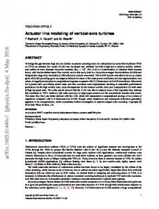
Using the corrected velocity time histories, values of inertia coefficient, CM and drag coefficient, CD for the rotor were computed using equations (5) and (6) and are plotted against KC in Fig. 5 for two different mean tip-speed ratios. A blockage correction has not been applied for this investigation which was conducted at a high blockage ratio. It will be assumed however that the effects of blockage and unsteadiness can be separated and a factor found from a momentum model can been applied to CM and CD as done by Whelan et al. [5] for power and thrust coefficients over a range of Λ.
0.8 0.6
Normalised trace
0.4 0.2 0 −0.2 −0.4 −0.6 Velocity Force
−0.8 −1 0
5
2.5
CD
2
µ = 0.08
µ = 0.22
1 1 ˙ FX = ρ u′ (t)|u′ (t)|AC′ D + ρ U 2 ACD + ρ u(t)VC M, 2 2 (10) where u′ (t) = u(t)-U and C′ D is the oscillatory drag coefficient. Fig. 7 shows the results of the reconstruction of the oscillatory part of the force using both forms of Morison’s equation. The Verley and Moe alternative form leads to a significant improvement in the agreement between the measured and reconstructed force, particularly at the lower Λ. The amplitude of the oscillatory force was consistently found to be higher in the lower Λ case as shown by Fig. 8.
CM 0
0
30
rotor. The drag coefficient in Morison’s equation has to represent both the mean and oscillatory force. Verley and Moe [10] offer an alternative form of Eq. (4) to model the axial force which provides more degrees of freedom to match these effects:
0.5
−0.5
25
Figure 6: Normalised force and velocity time histories.
1.5
1
10 15 20 Non−dimensional time τ
0.5
1
1.5
2
Figure 5: Variation of coefficients of added mass and drag with KC . -+- denote tests run with mean Λ = 8.5; -o- denote tests run with mean Λ = 11.
Over the range of KC numbers tested, and both at the high and low mean Λ, the coefficients of added mass are considerably smaller than the coefficients of drag and there appears to be no obvious dependence of CM on either KC or Λ. The error in evaluation of CM is very high due to the small absolute value, which amplifies any errors that could have been introduced by the approximate correction for the Seiche wave excitation. This large error accounts for the small negative CM values obtained and a mean line through the data points indicates that the inertia term is insignificant compared with the drag term. A plot of the normalised force and velocity time histories (as shown in Fig. 6) confirms that there is only a small phase difference between the two signals. Since added mass is a largely inviscid phenomenon and the key non-dimensional parameters (KC and Λ) have been matched these results can be scaled up directly to a full-scale device. At small values of KC the added mass of porous plates is relatively insensitive to KC and since the magnitude of KC numbers for incident wave interaction with a full-scale turbine are small, it is expected that the added mass is unlikely to vary significantly between wave states. The evaluation of the drag coefficient using equation (6) leads to a clear dependency on Λ. The magnitude of CD increases with Λ which concurs with the steady tests conducted by Whelan et al. [5] using the same
6
Oscillatory force (N)
4
2
0
−2 Measured force Morison Verley and Moe
−4
−6
0
5
10 15 20 Non−dimensional time τ
25
30
Figure 7: Reconstruction of force signal using various models for axial force.
4
Comparison with dynamic inflow models
In order to isolate the effects of dynamic inflow the same rotor used in the oscillatory tests was also subjected to a quasi-step change in axial velocity by towing it through a mean current. The flume was run at a flow 589 4
140
32 Mean Λ = 8.5 Mean Λ = 11
120
30
26 80
Force (N)
Oscillatory drag coefficient
28 100
60
24 22 20
40 18 20
0
16
0
0.5 1 1.5 Keulegan−Carpenter number (KC)
14
2
60
80
100
32 30 28
Force (N)
26 24 22 20 18 16 14
0
20
40
60
80
100
time (s)
Figure 10: Step response of the rotor in the presence of a mean current - simulated in GH Bladed.
be small. A secondary investigation comparing the rotational added mass of the turbine evaluated under these conditions from experimental measurements and a rotorblade strip-theory model based on Theodorsen’s theory is currently underway. The results of this investigation are to be incorporated into a Blade Element Momentum code as used in the industry. More details will be given in the presentation.
(11)
This differential equation has been incorporated into the Blade Element Momentum (BEM) code described in detail in Whelan et al. [5] (including the correction for the blockage conditions of the experiment) by replacing the quasi-steady BEM iteration with a time-stepping procedure. The conditions of the step change experiment described in the previous paragraph were input to the code. This BEM simulation led similar change in force magnitude and an even smaller overshoot in force after each step change as shown in Fig. 10, confirming the suggestion from the experiment that the effect of dynamic inflow due to a step change in axial velocity is small.
5
40
Figure 9: Step response of the rotor in the presence of a mean current - experimental measurement.
speed, U, of 0.3 m s−1 and the carriage was moved at a speed of 0.05 m s−1 in the downstream direction until it approached the end of the working section leading to two quasi-step changes in velocity at the rotor plane. The axial force response is shown in Fig. 9. A small overshoot in axial force is observed after each step change. No correction has been attempted for any Seiche wave that might be excited in the flume due to the movement of the rotor. These results agree qualitatively with work on wind turbines summarised by Snel and Schepers [4], in which dynamic inflow models predicted the effect of dynamic inflow due to a step change in axial velocity to be small. The Pitt and Peters [3] prediction for dynamic inflow is commonly used by industry for the inclusion of dynamic inflow effects on rotors, such as in the industry standard code GH Tidal Bladed [11]. The additional added mass used to model the dynamic inflow effect modifies the equation for the thrust coefficient that is derived for unconstrained flow obtained by applying mass conservation and Bernoulli to a first order differential equation in terms of the axial induction factor, a: 16 R32 − R31 a. ˙ 3π U R22 − R21
20
time (s)
Figure 8: Oscillatory drag coefficient.
CT = 4a(1 − a) +
0
Acknowledgements We would like to acknowledge the help and support of Garrad Hassan and Partners. This work is partly supported by the Engineering and Physical Sciences Research Council through a research studentship.
References [1] Carbon Trust. UK tidal stream resource assessment (Phase II). Black and Veatch Ltd, 2005. [2] G. McCann, M. Thomson, and S. Hitchcock. Implications of site-specific conditions on the predictions of loading and power performance of a tidal stream device.
Conclusions and future work
The axial added mass of rotor operating in a mean current and subject to passing waves has been shown to 590 5
Int. Symposium on Fluid-structure interactions, Aeroelasticity, Flow-induced Vibration and Noise, New Orleans, USA, 2002.
In Proc. 2nd Int. Conference on Ocean Energy, Brest, France, 2008. [3] D. M. Pitt and D. A. Peters. Theoretical prediction of dynamic inflow derivatives. Vertica, 5(1):21–34, 1983.
[8] C. Y. Zhou and J. M. R. Graham. Numerical study of cylinders in waves and currents. Journal of Fluids and Structures, 14:403–428, 2000.
[4] H. Snel and J. G. Schepers. Engineering models for dynamic inflow phenomema. Journal of Wind Engineering and Industrial Aerodynamics, 39:267–281, 1992.
[9] C. A. Coulson. Waves. University Mathematical Texts, 1941.
[5] J. I. Whelan, J. M. R. Graham, and J. Peir´o. A freesurface and blockage correction for tidal turbines. Journal of Fluid Mechanics, 624:281–291, 2009.
[10] R. L. P. Verley and G. Moe. The effect of cylinder vibration on the drag force and the resultant hydrodynamic damping. Technical Report STF60 A79061, Norwegian Institute of Technology, 1978.
[6] P. W. Bearman, J. R. Chaplin, J. M. R. Graham, J. K. Kotense, P. F. Hall, and G. Klopman. The loading of a cylinder in post-critical flow beneath periodic and random waves. In Proc. 4th Int. Conference on the Behaviour of Offshore Structures, Delft, the Netherlands, 1985a.
[11] E. A. Bossanyi. GH Tidal Bladed - Theory Manual. Technical Report 282/BR/009, Garrad Hassan and Partners Ltd, 2007.
[7] J. Wang, M. J. Downie, and J. M. R. Graham. Mean and oscillatory flows past porous plates. In Proc. 5th
591 6