Insights from Building a Prototype for Model-based On-board Diagnosis of Automotive Systems Peter Struss1,2, Martin Sachenbacher2 and Claes Carlén3 1
OCC’M Software GmbH Gleissentalstr. 22 82041 Deisenhofen Germany
[email protected]
2
Technische Universität München Department of Computer Science Orleansstr. 34, 81667 Munich, Germany
[email protected]
Abstract Within the European "Vehicle Model based Diagnosis" (VMBD) project, demonstrator vehicles with built-in faults provided a serious challenge to model-based diagnosis techniques and a real-life test-bed for their evaluation. One of the guiding applications within VMBD was model-based on-board diagnosis of faults in a turbo diesel engine system with a focus on potential origins of increased carbon emissions. Our goal was to build a demonstrator system that is able to run on-board, processing the signals available to the ordinary control unit. This paper does not aim at presenting new theories and technologies, but focuses on the application aspects and the lessons learned: What did work? And what needs to be done? First, we analyze the requirements imposed, the way they were addressed by the chosen solutions, and the results obtained by the on-board diagnosis prototype running on the demonstrator vehicle. The most important challenges of the demonstrator were to apply model-based diagnosis systems to dynamic systems with feedback, to handle systems without a rigorous mathematical model (such as the combustion engine), and to try to provide the response times required for real-time applications. Second, we discuss, based on our experience, the obstacles to transferring the technology to industrial application that we found or foresee. The main ones are related to modeling and a narrow perspective on diagnostic processes; some of the problems are caused by the inertia of current work process organization and the fact that modeling and diagnosis in industry is the domain of engineers, who maintain views and techniques that are rather different from ours. Despite these non-technical origins, the problems raised pose demanding challenges to research in modelbased systems, and we believe they might be helpful for the research community to guide and focus its efforts.
Introduction Research on model-based diagnosis (e.g. [Hamscher et al. 92], [Dressler and Struss 96]) has generated a number of well-founded theories and sophisticated prototypes of implemented diagnosis engines. However, many of these Copyright © 2000, American Association for Artificial Intelligence (www.aaai.org). All rights reserved.
3
Volvo Car Corporation IT & Product Documentation, Department. 98101, PVS3 40508 Göteborg, Sweden
[email protected]
diagnosis systems have only been applied to toy examples or to problems that ignored the practical context of industrial applications. As a result, the transfer of the technology into practice is well behind the expectations, despite the fact that it promises to meet some crucial requirements of automated diagnosis for industrial needs. Car industries provides a good example of such industrial needs. It is estimated that European passenger cars have an average yearly down-time of 16 working hours due to malfunctions and maintenance. This figure is even greater for commercial vehicles. For the European Community alone, this amounts to a total of over one billion hours for diagnosis and repair. At the same time, with increased environmental awareness, stricter constraints are imposed on the car manufacturers to develop clean cars, and also to keep them clean during their life cycle (see, for example, [OBD 93]). These growing constraints are reflected in increased requirements on on-board diagnostics development. For engine management control units, currently about one half of the software is dedicated to diagnosis, and this share is still growing. In response to this situation, several car manufacturers and suppliers joined to launch the Brite-EuRam project VMBD (Vehicle Model Based Diagnosis) with the intention to promote the transfer of model-based diagnosis technology by the challenge of applying it to on-board and off-board diagnosis of passenger cars. The results and system performance were evaluated on real demonstrator vehicles. Within this project, Volvo Car Corporation, Robert Bosch GmbH, and OCC’M Software GmbH produced a modelbased system that diagnoses problems related to increased carbon emissions of diesel engines, a problem of significant importance w.r.t. environmental impact and compliance with legal requirements. The system transforms the sensor signals that are available to the standard electronic control unit (ECU) on-board to a qualitative level and exploits them for detecting and localizing faults based on a model of the turbo control system. It has been installed on a Volvo demonstrator vehicle with a number of built-in faults. The goal of this work was to face the requirements imposed by this kind of application. In particular, we expected answers to questions like: • Are model-based diagnosis systems able to diagnose
dynamic systems with feedback (like a turbo control system)? If they are, • can they provide a sufficient response time (for fast processes like the ones in the engine)? And, even more fundamentally: • Are they applicable if no rigorous mathematical models are available (as is the case for the combustion process)? In this paper, we do not intent to present new research results, but to share our experience regarding the application aspects of this work.. We start with a brief explanation of the respective vehicle subsystem and then discuss the most relevant requirements that had to be addressed. Then we outline the technical solutions we adopted and discuss how and to what extent they satisfy the requirements introduced. Next, we describe the set-up of the experiment and summarize the results obtained. Finally, we discuss some lessons learned about possibilities and obstacles in the transfer of the technology into industrial applications, and propose some research directions the community should focus on in order to address this.
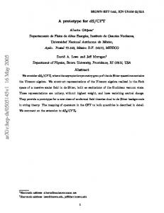
The Application Domain The demonstrator vehicle used in the VMBD project is a Volvo car equipped with a so-called distributor-type diesel injection (DTI) system ([Bosch 97]). The DTI is an approved system which has been on the market for many years. Recent increases in legislative and customer demands, however, have lead to new requirements related to aspects of emissions and performance of this system. Figure 1 shows the part of the system which is responsible for supplying air to the diesel engine. It can be decomposed into the exhaust gas recirculation (EGR) subsystem (upper part of Figure 1) and the turbo control subsystem (lower part of Figure 1). EGR converter EGR valve ECU
Wastegate valve
Turbo control valve Boost pressure sensor Air mass meter Turbo Unit
Converter
Figure 1: Turbo control and exhaust gas recirculation subsystem of the DTI The purpose of the exhaust gas re-circulation system is to return a certain amount of the exhaust gas to the intake air
to decrease the oxygen rate of the intake air and thus to reduce emission levels of the fuel combustion. Depending on driving conditions, the ECU governs the EGR converter to achieve a certain air pressure in a control pipe, which in turn sets the position of the exhaust gas re-circulation valve. The position of this re-circulation valve then determines how much of the exhaust gas is fed back to the air intake pipe. The turbo control subsystem consists of a turbo-charger turbine, which is driven by the engine’s exhaust gas, for compressing (and thereby increasing the mass of) the air taken into the engine. The ECU controls the boost pressure (i.e. the pressure in the engine intake pipe) admitted in a certain driving situation by opening or closing the turbo control valve, which determines the position of a so-called waste-gate valve. The position of this valve determines how much of the exhaust gas drives the exhaust turbine of the turbo-charger. The ECU not only issues commands to the actuators, but also monitors and checks the sensor values it receives from these systems. The goal of this so-called on-board diagnosis is to signal alarms to warn the driver in case of a failure and to generate fault codes that can be further used in the service bays to track down a failure. For failures which are considered critical, on-board diagnosis also aims at selecting appropriate recovery actions. The built-in recovery actions that will be performed depend on the assumed failure and the expected failure effects and range from minor performance reductions to full engine stop. They attempt to take the vehicle back into safe operational conditions (so-called limp-home modes), which allow the driver to reach the next service bay, for instance. The design of such diagnosis capabilities has to cope with a number of fundamental challenges: Variant problem. The systems come in many different variants. The DTI system we dealt with is only one specific instance. The reason is that a supplier of automotive subsystems has to develop his products for many vehicle manufacturers and a lot of vehicle models, which all impose different requirements on the base system. The actual configuration may differ in the number of sensors, and redundant parts may be present or absent dependent on the specific car manufacturer. Also, the components themselves come with different constructive details. These modifications must be thoroughly handled in the diagnosis algorithms. However, generating specialized diagnostics for all variants by hand is a very expensive task. Safety criticality. On-board diagnosis on a passenger vehicle is a safety-critical application, i.e. neither should the driver be confronted with false alarms, nor should (critical) faults be missed. This demands for methods that enable complete and correct analysis rather than "heuristic" approaches. Dynamic and controlled subsystems. The above device is a controlled system which has internal states depending on previous inputs. Hence, failures may be observable only in
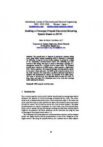
a subset of the operating modes of the vehicle (e.g. engine start, idling, take off phase, full acceleration, etc.) or transitions between operating modes. For example, the pressure in the air hose between the turbine outlet and the intake manifold of the engine varies, depending on driving conditions, from atmospheric low pressure (during idling) to about 2 bars overpressure (during full acceleration). A leakage at this point may therefore, depending on its size, only be perceivable during high power demands. Additionally, the control unit tends to compensate for failures during certain operating modes. As an example, Figure 2 shows measurements taken for an electrical failure in the air mass sensor (which is a combination of air flow and air temperature meter). The failure has an effect only when the engine is idling, while it is compensated for during driving. This all becomes a problem especially in combination with low measurement granularity, that is, if measurements within feedback loops are sparse over time. Determining correct diagnostics that cover these situations is a complex task, often infeasible for hand-crafted diagnostic procedures which are based on predefined range or plausibility checks only. Limited system information. The knowledge about the behavior of some vehicle components, especially components that involve several physical domains like the engine and its combustion process, is incomplete and precarious. Particularly in the case of a failure, quantities are not known exactly or even remain unknown. In contrast to electric or hydraulic components, there exist no general mathematical models one could start from. However, to exploit the kind of symptoms we are interested in, it is necessary to establish a link between emission- or performance-related phenomena and components in the various subsystems (e.g. a too high exhaust gas recirculation rate or a too low pressure of the intake air). To some extent, it is therefore necessary to reason about the behavior of such ill-specified components as well. Limited observability. Very few sensors are available in car systems. This is true e.g. for the hydraulic part of the fuel injection system, which contains no sensor at all. In addition, the context in which a car is operated in (e.g. road and weather conditions, load) is highly dynamic, uncertain and often neither measurable nor reproducible. The main consequences are noisy signals and rather qualitative symptom descriptions. Diagnosis has to be capable of processing such information. Real-time requirements. On-board diagnosis must come up with a conclusion before the system has to move to another state (e.g. shut off the engine) to prevent safety-critical situations or severe system damage, or to comply with legal restrictions. As a consequence, the computational requirements of on-board diagnosis functions must be relatively low to bring them into state-of-the-art ECU. Currently, the DTI control unit is equipped only with a restricted form of on-board diagnostic capabilities. It continuously monitors part of the sensor signals using predefined range and plausibility checks and is able to
detect a limited number of faults on this basis. However, in many cases it fails to discriminate among the different possible causes that lead to the failure. Consequently, it sometimes applies a more restrictive recovery action than would actually be necessary. One way to improve this would be to exploit more of the interdependencies between different signals. But currently, this is not done in a general and systematic way, leading to sub-optimal solutions. Air mass [mg / stroke]
1000 idling
driving
idling
900 800 700 faulty 600 500
normal
400 300 0
Time [sec] 5
10
15
20
25
30
Figure 2: Measurement for a failure that is compensated during driving and shows up in idle mode This reflects the fact that at present the development ("design") of automotive on-board diagnosis does not follow precisely defined methodologies or criteria and is generally regarded as an addendum to the design of the system. On the other hand, a growing interest of car manufacturers lies in the possibility to utilize the same set of techniques for all phases of the design process (e.g. for pre-design, function-design and layout of the diagnostic concept), as well as for diagnosis and fault tracing in the service bay. Since car manufacturers work with a number of system and component suppliers, there is a high, but currently unfulfilled, demand for developing a standardized methodology among the parties involved. Our goal thus was • to produce a prototypical model-based diagnosis system that is capable of diagnosing faults in the diesel engine based on the sensor signals that are available to the ordinary ECU, • to this end, generate a library of models of the relevant components, and • to perform this task in a systematic way as a contribution to a general methodology for producing on-board diagnostics. In other words, on the one hand the prototype had to solve the specific problems given by the fault scenarios on the real vehicle. On the other hand, the method for obtaining the solution should be applicable to a broader class of automotive subsystems and diagnosis problems. While the first task is certainly achievable with current practice in engineering, the second goal in our view promises merits to be earned by AI technology.
Technical Foundations of the Prototype In the following subsections, we briefly outline the technical foundations of the implemented prototype and discuss in what way and to what extent they address the requirements described in the previous section. The goal of this paper is not to present all underlying theoretical results; for technicalities, the reader is referred to the referenced papers.
Consistency-based diagnosis with Compositional Models The choice of a model-based approach is founded on the recognition that most complex subsystems in a vehicle share the following features with respect to their function: • there exists a natural decomposition into subsystems with only few component types, • in most cases, malfunctions of the car or a subsystem are due to some component failure, • component behavior can be described by relations among local variables and parameters, • system behavior is established by the behavior of its components and their connections w.r.t. processing of material, energy or signals. A consistency-based approach to diagnosis ([Hamscher et al. 92]) has the desired property to systematically exploit the analytic redundancy among the available sensor signals. The model-based approach alone provides one answer to the methodological challenge, because its underlying principles are independent of the particular subsystem and enable the re-use of the involved software components. As stated above, component-oriented modeling is a natural approach in our application domain. Beyond this, it is the key to solving the variant problem, because the model of a subsystem is derived as the aggregation of standard building blocks. This is another element of a general methodology and enables the automated generation of a device model and, hence, of a tailored diagnosis system based on a structural description of the device only (which should be the natural output of a CAD system). The specific architecture of the prototype has the consequence that we do not need to build a model of the control unit behavior, unless we want to detect faults within the ECU. Due to the fact that the model runs within an onboard environment, all the control unit signals will be available for observation. Consequently, a behavior model of the control unit can never be part of a diagnostic hypothesis.
State-based diagnosis of Dynamic Systems As outlined above, consistency-based diagnosis requires checking whether the behavior that is predicted by the model is consistent with the observed behavior. If we apply this diagnosis approach to dynamic systems like in our application, a crucial question is whether this requires prediction of behavior over time, i.e. simulation. It turns out that diagnostic results can be obtained based on
checking consistency of observed and modeled states only, i.e. without performing simulation. The approach of state-based diagnosis then checks only if the set of observed states occurs in the set of possible states of the system. Since the actual order in which states occur is thus not taken into account, this might seem much weaker than a simulation-based approach which compares the actual behavior over time and the model behavior simulated over time. However, in [Struss 97] it has been shown that under certain conditions, the results are equivalent. Avoiding simulation and performing the consistency check for states only provides a great computational advantage, in particular, if the system needs not simulate possible faults, and is one contribution to achieving the required response times of the diagnosis system. Another contribution from the algorithmic part to meet onboard time restrictions for diagnosing dynamic systems comes from techniques for re-using predictions over different time points (see [Dressler 96]). On top of a statebased approach, this "temporal caching" enabled to run model-based diagnosis fast enough to cope even with realtime requirements, as shown in the section presenting the results.
Qualitative Models and Qualitative Deviation Models A second key to provide the efficiency that enables to run model-based diagnosis even on-board a vehicle is to avoid the computational complexity of numerical modeling and simulation on the part of the model. The consistency-based diagnosis principle is independent of the specific modeling formalism and works, for instance, with numerical component models. But, as pointed out, if systems operate in an ill-specified environment, accurate component models might be unavailable and/or unnecessary, partly because of the nature of the involved processes (e.g. friction or combustion) or because parameters change due to wearing. A qualitative model provides an appropriate answer to these issues; it also helps to keep the library of model fragments manageable (but see the discussion in section 5). It turns out that in some cases it is not even relevant to reason in terms of the actual values of quantities. Rather, it can be sufficient to reason in terms of (qualitative) deviations from nominal values only. For example, if the EGR valve closes (much) slower than normally, the oxygen rate of the intake air will be (substantially) lower than normally. It may suffice to explain why the oxygen rate is lower than it should be, regardless of the actual value of the oxygen rate. Descriptions of deviations can reflect the fact that it may be unnecessary or impossible to specify the normal behavior exactly and numerically. For each variable, such a deviation can be represented as ∆x := xact - xref. Based on this, component models can be formulated that introduce and propagate deviations from some nominal or
reference behavior (which is possibly left unspecified), even across different domains. This potentially avoids the necessity to specify the correct behavior of components explicitly, which can provide one answer to the problem of limited system information. In [Sachenbacher et al. 98], we developed a theoretical foundation of such deviations that is not restricted to simple functions as in the example. In particular, the resulting notion does not fix the reference that is used for comparison. Using the nominal behavior as a reference is a natural option for diagnosis, but not the only possibility. What is exploited to construct deviation models from the underlying equations is that the same set of constraints holds for both the actual and the reference values. This is why we can also interpret two time points t0, t1 in such a way that previous observations at t0 represent a reference value and the actual observations at t1 are to be compared with this reference: ∆x(t1,t0) = x(t1) - x(t0). Although the interpretation of a "deviation" is now a (significant) change in time, the deviation models hold for any pair of time points t0, t1. Capturing such temporal changes in the behavior models and the observations of the device is a way to avoid having to calculate derivatives based on noisy signals, which are present in our application. The idea is that while derivatives at a single point in time might be unobservable, deviations of signals over some (significantly large) time interval can be observed. If we have a model that relates such deviations of variables (or their integrals) over time, this can be used for diagnosis in the state-based framework. This presupposes that we are adequately supplied with observations about deviations over time. In our prototype, such deviations over time are computed from the observed signals. Currently, this is based merely on a pre-defined, restricted schema for determining past time points t0 as suitable reference.
environment for diagnostic models as well as a run-time version of a consistency-based diagnosis engine. The diagnosis engine performs behavior prediction using the qualitative observation vectors and the model in a statebased framework, where it re-uses, if possible, existing predictions from previous observation vectors (section 3.2). The diagnostic result is derived as the combination of the results obtained for each individual observation vector.
Demonstrator Car Set-Up In the VMBD project, a Volvo 850 TDI demonstrator car was made available for hands-on experimentation with the DTI application. Failures can be induced in the car during various operational conditions of the engine with the model-based diagnosis system running, and the results can be compared with the conventional diagnostic capabilities of the control unit. The various failures in the demonstrator car can be adjusted by potentiometers and triggered by switchboards from inside the passenger compartment (see Figure 3). A pneumatic leakage, for example, is simulated by additional valves opened and closed by electrical switches.
Evaluation on the Demonstrator Vehicle Prototypic On-board Diagnosis System The software for the on-board diagnosis prototype consists of the following components: • a module for the conversion of raw signals into qualitative observations, and • a model-based run-time system that performs diagnosis on the basis of these observations. The former point comprises a component for the conversion of quantitative signals into qualitative values and qualitative deviations as described in section 3.3. Each time a change of observed variables or their deviations occurs on the qualitative level, a new vector of observations is created and handed to the diagnosis engine. For the latter point, we used components of the commercial RAZ’R system ([Occ’m 00]) that offers a development
Figure 3: View of the Volvo Demonstrator Car showing the notebook connected to the ECU. The glove compartment (behind) contains the switchboard for controlling the builtin faults. For these experiments, additional interfaces and devices had to be installed. Given that the ordinary control unit and its diagnosis algorithms should work in parallel without interruption (for safety reasons), and the model based diagnosis prototype needs the same information about the sensor signals as the current ECU, the architecture of the measurement facilities was chosen as shown in Figure 4. At present, control units still have rather limited computing power which prevented us from integrating the modelbased diagnosis system within the ECU software. To circumvent this restriction, a so-called application control unit was used in the demonstrator. Application control units are normally used for calibration of ECU software for a
specific vehicle type and are equipped with special dualported memory chips such that in principle all variables and signals of the control unit are accessible in real time, without interfering its normal operation. The data of the vehicle is interfaced to the model-based diagnosis prototype, which is running on a portable PC inside the passenger compartment. In Figure 4, ETK is a hardware interface closely attached to the application ECU providing access to its controller bus. MAC is a protocol conversion box which stores the information gathered from the ETK, while VS100 is a commercial tool that car suppliers use for acquisition, storage, interpretation and display of control unit data. It runs on the same portable PC as the on-board diagnostic prototype. The AD-Scan device and the PC Tester allow to read in further signals (dotted lines) from additional sensors or workshop equipment for the purpose of off-board diagnosis in the VMBD project.
diagnostic (K-) line
MAC 2
ETK
ECU
serial line
VS100 RAZ’R
installing an electric motor which opens a valve to release pressure from the inter-cooler system via a 12mm opening. If the leakage is opened, air (oxygen) mass is lost after having passed the air mass sensor. The fuel quantity calculated by the control unit which is based on this signal will therefore be too high for the actual amount of oxygen in the combustion chamber. This leads to incomplete combustion of the diesel fuel, which causes increased carbon emissions in the exhaust gas (due to non-burnt particles) and reduces the torque of the engine. This effect is, depending on the driving condition, perceivable for the driver as black smoke emerging from the exhaust system. In another scenario, a wrong flow from the exhaust gas recirculation (EGR) system occurs due to a faulty signal or mechanical failure in the EGR valve. The real fault installed in the car consists of a switch used to control a magnetic valve that allows ingress of atmospheric pressure in the EGR valve, thus causing it to open outside its normal operating region. The rest of the scenarios involved faults in the boost pressure sensor, airflow sensor and engine temperature sensor. These faults are injected in the car by electrically manipulating the respective signal to the control unit.
Measurements
AD-Scan parallel line
PC Tester Multimeter
Figure 4: Architecture for data acquisition in the demonstrator car Although this means that the model-based diagnostic software is not really running on-board within the ECU, we consider this solution adequate for our case studies since it provides all important constraints except the space and computing power limitations of the ECU. This aspect is beginning to be more and more relaxed in practice, anyway.
From the available control unit data, the following subset of signals was fed to the prototype for diagnosing the described scenarios: • atmospheric pressure sensor signal • boost pressure sensor signal • mass airflow sensor signal • engine speed sensor signal • duty cycle of the turbo control valve • current fuel quantity injected The on-board diagnosis prototype uses only these control unit signals, and no further signals from additional sensors. The frequency at which the control unit reads the signals from the sensors varies with the speed of the engine, therefore the time points at which observations occur are not evenly distributed.
Diagnostic Results Diagnostic Scenarios We were particularly interested in failures that cannot be captured or are hard to capture by traditional on-board diagnosis. Since increased legislative and customer demands have lead to new requirements especially for aspects related to emissions and performance of the system in the Volvo car, we concentrated on effects that involve incomplete fuel combustion and increased carbon emissions due to an excessive quantity of fuel injected or insufficient airflow to the engine (called "black smoke" problems). One scenario in the demonstrator car consists of a leakage in the air hose between the turbine outlet and the engine intake manifold. The scenario was realized in the car by
In our experiments, we have injected the above failures in various operating modes of the car, such as idling, driving with constant speed, full acceleration and stalling. We present results for the leakage scenario in more detail. The leakage has an effect only if the pressure in the hose (i.e. the boost pressure) is significantly different from the pressure outside (i.e. the atmospheric pressure), which means that the failure is not visible e.g. during idling. Figure 5: Screenshot of the model-based run-time diagnosis prototype for the DTI turbo control subsystem. shows the diagnostic results for a slowly opening leakage during stalling the engine. The upper part of the window shows the control unit signals listed above. The measurement runs for 9.75 s and yields 1064 quantitative observation vectors.
Scenario
Fault detected
Realtime
yes
No. of (single) component fault hypotheses 2
No. of qualitative vectors generated
9.75 sec
No. of quantitative vectors 1064
12
Runtime (using temporal caching) 3.91 sec
Air intake pipe leakage Boost pressure signal too high Airflow sensor signal too high EGR valve opens outside normal operating region Engine temperature signal too low
yes
3
12.20 sec
1417
10
5.04 sec
yes
6
14.40 sec
1887
22
6.65 sec
yes
7
18.61 sec
1676
4
2.43 sec
no
-
21.08 sec
2003
6
2.22 sec
Table 1: Summary of diagnostic results for the on-board prototype (showing typical instances of measurements) The signal transformation module reduces them to only 12 qualitative observation vectors (indicated by the small "peaks" at the base of the signal window). Based on these observations and the model, the runtime system successively reveals three sets of conflicting assumptions: • {Junction1, Intake Turbine, Junction3, Engine, Airflow Sensor, Junction2, Pressure Sensor}, • {Junction1, Intake Turbine, Junction3, Engine, Airflow Sensor, Junction2, Speed Sensor}, • {Junction3, Engine, Speed Sensor, Pressure Sensor}.
Figure 5: Screenshot of the model-based run-time diagnosis prototype for the DTI turbo control subsystem. Here, the component names stand for the assumption that the respective component is working correctly; i.e. at least one component in each of the above sets must be faulty. The three different conflicts combine to two single fault hypotheses and a number of multiple fault hypotheses: • {Junction3} • {Engine} • {Pressure Sensor, Junction1} • {Pressure Sensor, Intake Turbine} • {Pressure Sensor, Airflow Sensor}
• • • • • •
{Pressure Sensor, Junction2} {Speed Sensor, Junction1} {Speed Sensor, Intake Turbine} {Speed Sensor, Airflow Sensor} {Speed Sensor, Junction2} {Speed Sensor, Pressure Sensor}
The two single fault hypotheses contain the component where the failure was actually induced ("Junction3", see mark in Figure 5: Screenshot of the model-based run-time diagnosis prototype for the DTI turbo control subsystem. within the window depicting the system structure).The runtime for the example (on a Windows/Pentium PC) is 25.85 seconds without using temporal caching, and 3.91 seconds if temporal caching is activated. This means that, for this example, the performance of the on-board system is in the order of magnitude of real-time. Similar results where achieved for the rest of the scenarios. Table 1 summarizes the results. Note that the current control unit software, based on the same signals, is not able to detect any of the above failures. Because some failure effects are noticeable only during certain operating conditions, the diagnosis system cannot always determine a unique diagnosis, but rather yields a number of hypotheses as in the example above. E.g. for the scenario with the boost pressure sensor out of tune, the diagnosis system yields two conflicts and outputs a list of three single faults which contain the boost pressure sensor as one possible candidate, but also other components that together could account for the same symptoms. In these cases, knowledge about the behavior of faulty components, i.e. fault models, could be used to further constrain the set of diagnostic candidates. So far, only models of correct behavior have been used for the diagnostic experiments. At least in some cases, there is evidence that fault models could be useful to partially compensate for the limited observability, and thus to further restrict the diagnostic candidates.
Lessons Learned The Success Story The demonstrator described in this paper proved the feasibility of the technology in the automotive domain. It can provide a basis for a systematic and cost-effective approach to creating diagnostics for car subsystems, and it has the potential to improve the quality of diagnostics by handling fault situations that are not covered by current onboard diagnostics, or by improving fault identification up to a point where more specific recovery actions can be chosen. In particular, the demonstrator illustrates that model-based techniques are suited to address several requirements that are important to, but not limited to, car diagnosis: • the variant problem by compositional modeling and model-based generation of diagnostic solutions, • safety criticality by a systematic approach and completeness of results w.r.t. the model, • dynamic systems by modeling changes over time as temporal deviations and by performing state-based diagnosis (enabled by sufficiently dense measurements), • limited system information by modeling complex elements like the combustion process at a qualitative level and by an appropriate qualitative abstraction of noisy signals, • real-time requirements by processing only qualitative changes in the measurements and by applying statebased diagnosis with temporal caching. Which perspective is opened by the demonstrator? Of course, memory on current control units is limited. But this is going to change very soon, and the concept of a so-called "car PC" ([Intel 00]) may be approaching even faster. But the work on the prototype as part of our efforts towards deploying model-based diagnosis as a technology in the automotive industry has increased our awareness of a number of theoretical, methodological, and organizational problems that will have to be solved in order to improve the utility of our technology. In the following, we discuss some problems and shortcomings related to the demonstrator and the development process before trying to draw some general conclusions about the current state and the future of model-based diagnosis.
Diagnosis - More than Candidate Generation What our current demonstrator, like most of the implemented diagnosis systems, does is candidate generation: Given a system model and a set of observations, what are the diagnostic hypotheses that can be derived from them? More specifically, it performs fault localization, i.e. diagnostic hypotheses are (sets of) possibly faulty components. If we add fault models in a new version of the demonstrator, it will realize fault identification: hypothesizing possible (sets of) specific component faults.
While this is a useful goal to achieve, there is still something crucial lacking: an explicit representation and exploitation of the goal of the candidate generation step, namely therapy: Re-establish the functionality of the respective system if or as far as possible within given conditions. Again like many other diagnostic systems, the demonstrator terminates fault identification when it has generated a set of assignments of behavior modes to components that are the most plausible ones under some criterion. This appears to be fairly appropriate if therapy consists of component replacement, as in workshop diagnosis. But on-board diagnosis has a totally different goal: to determine the appropriate recovery actions. Today, there are a number of predefined reactions of the control unit, ranging from stopping operation of the vehicle via special control schemes for modified continued operation to just turning on a warning lamp. Which one is appropriate is not so much dependent on the defect component (if any), but on the type of fault or disturbance. In particular, this means that the severity of the fault (in terms of potential damage and threat to safety) rather than its likelihood usually determines whether or not it has to be considered which is likely to be in conflict with focusing and control schemes of current diagnosis systems. Discrimination has to pursue a specific goal, and our current theories and systems have no systematic way of expressing this and allowing to control the diagnosis process under this goal. Interpreting this finding in a more general way, we have to notice that even fairly well-established pieces of our technology have limited means for reflecting the practical context and conditions of the diagnostic tasks they might be used for.
Modeling - More than Libraries Building the model library was one of the major tasks and achievements in the project. For our demonstrator, it was mainly carried out by AI researchers with input from engineers from the automotive companies. Actually, we consider it a remarkable aspect of the model-based technology that it enabled non-experts in car technology to produce a diagnosis system whose results conform with conclusions of experts! The resulting models seem to do their job for the demonstrator. But to what extent will they do their job as re-usable elements of a model library when applied to a different problem? In our solution, every non-zero value for xact - xcorr is considered a deviation. However, what we are interested in are significant deviations, where "significance" is determined by the absence or existence of functional disturbances. We reckon that it is not possible to derive well-defined and useful deviation models capturing this intuition purely within the qualitative domain of signs. The reason is that significance in the sense stated above will vary with the function and system considered. A certain deviation of an internal parameter may significantly disturb one function or operating mode, while being irrelevant to
another one. For example, the connections to the turbo control valve branching off the air intake pipe of the engine are thin hoses with only some millimeters in diameters, whereas the intake pipe itself measures several centimeters in diameter. A leakage in the pipe connecting to the turbo control valve, therefore, would not affect the boost pressure in a significant way. We can express this by allowing a positive pressure deviation in the small pipe to be compatible with a zero pressure deviation in the bigger pipe. We introduced in our model a special type of separation component that describes such constraints, which can be interposed e.g. at junctions of pipes with significantly different diameters. Clearly, this is only an ad-hoc solution. Yet, the problem to characterize what makes a certain distinction to be significant is a fundamental issue, as using qualitative models (and signal abstractions) is crucial to achieving the performance required for on-board diagnosis. Whether or not a distinction in the domain of a variable or parameter is significant cannot be determined locally, but depends on the context, for instance on whether or not it causes another component to change its operating mode or leads to a disturbance of the desired function. There is a related problem. The device under consideration (like other automotive systems) comprises a discrete systems (the control unit software), standard physical components (electrical, hydraulic, pneumatic ones), and elements for which no rigorous mathematical model can be derived (the combustion engine). Consequently, models of the various parts come at different granularity, ranging from continuous-valued variables governed by a set (differential) equations for the physical part to discrete control signals and characteristic lines or characteristic maps for components or parts of the system for which no rigorous mathematical model exists (see e.g. [Nyberg Perkovic 98]). What we would like to have is support to the composition and smooth integration of such independently developed, "hybrid" component models, for instance by determining tailored qualitative distinctions in the domain of continuous variables reflecting the given distinctions in other parts of the model and its specific structure. From a broader perspective, the problem of deriving models that perform exactly the relevant inferences is not only a matter of the granularity of the variable domains. More generally, it has to be decided which set of phenomena have to be covered. For instance, models of some pipes and hoses in our application example need to capture the transportation of oxygen, carbon oxide, etc. However, this is irrelevant e.g. to the pipe that connects the turbo control valve to the waste gate valve, for which only pressure matters. Again, which features to include in a model, depends on the context and the task and is not straightforward. Is it necessary or not to propagate information about air temperature and oxygen rate from the air intake to the turbo control valve? We have been able to develop satisfactory models for our demonstrator. We can do it for another one and might also be able to improve their utility for a broader class of
applications. However, it would be our task and a timeconsuming one. This is another serious obstacle in the process of deploying the model-based diagnosis technology.
Signal Interpretation - More than Signal Preprocessing The potential of the temporal deviation models we used and the algorithms for the computation and exploitation of temporal deviations need to be further explored, both empirically and in their mathematical foundations. In particular, the possibilities of deriving such deviation models from arbitrary differential equations in a systematic way, as well as the selection of appropriate time points for comparison, still need theoretic investigation. To use such types of models has an impact on the signal transformation component, too, since it requires this component to compute the deviations of (integrals of) signals also. Under a broader perspective, this highlights a fundamental issue. On the one hand, the theory of signal processing offers a wide variety of filters and algorithms in order to interpret measured data. On the other hand, employing this in the context of qualitative models raises several problems. First, one is often left with the problem which kind of method and which parameters to choose for a specific application and model. A second, deeper problem is the fact that these methods hardly reflect the goal the resulting signal will be used for. Model-based reasoning is different from the traditional applications of these methods, like e.g. smoothing a signal such that its display on the dashboard appears less erratic, or fault detection based on predefined thresholds of signals or residuals. It is different because it becomes necessary to express an explicit "belief" in the observations once they are used for sophisticated logicbased reasoning, and in particular for refuting behaviors in diagnosis. As a consequence, if we want to move away from handcrafted solutions of coupling model-based systems with sensor measurements, we must find ways to (automatically) harmonize the granularity of the observations, the granularity of the model, its underlying assumptions and the task it is used for. While approaches exist in each of these directions, a general answer to this problem is still beyond the current state of the art.
Transfer to Industry - The Inertia of Current Practice So far, we pointed out some theoretical and technical problems that need to be addressed to promote technology transfer. But even if this were not the case, actually installing the technology in control units on vehicles does not appear to be the next feasible step. There are major obstacles arising from organizational and "cultural" problems. As we pointed out, our technology is offering a number of very attractive and cost-effective features and benefits to industry. But with this offer, we are not entering
a "white spot" on the map of current industrial work processes during the product life cycle. There are probably hundreds of thousands of experts on car diagnostics successfully solving problems, including mechanics in the workshops and engineers designing on-board systems, and they do so in established work processes, with a certain education, using particular tools. In our domain, we are facing mainly experts with an engineering education and equipped with some experience. The point is that we are not simply offering a new tool that simplifies or improves some tiny step in their work, such as a better data base interface, a faster version of a simulator, something they can easily switch to and benefit from immediately. Model-based systems interfere with their knowledge and crucially with the content of their expertise. That these systems change the work process dramatically, is actually one of their great potentials, but first, exactly this forms a serious obstacle to their introduction. Of course, engineers are accustomed to perform modeling. But even this may turn out as a problem rather than an advantage, because it usually means hand-crafting specialpurpose, often black-box, mathematical and numerical models. Building model libraries with context-free behavior models at a conceptual level for automated model composition is a quite different task. As a result, the confidence in model-based systems, the preconditions in terms of education and organization of work have yet to be developed, and this is something that needs time, even if there is a serious commitment of management . The consequence is that the solutions-in-principle found in the demonstrators will have to be turned into tools that support the actual work process, for instance for analysis of diagnosability, sensor placement, and FMEA. This also involves the integration with other tools, such as simulation systems and CAD tools. The results of VMBD lead to a follow-up project that again joins a number of car manufacturers (Fiat, DaimlerChrysler, Peugeot, Renault), a supplier of vehicle subsystems (Magneti Marelli), a software company (OCC’M Software), and research groups from European universities. It aims at turning the technology into tools for the current design process of on-board control systems.
Merits and Challenges Mature for Application! In this section, we attempt to generalize from the experience with the demonstrator discussed above. What do we conclude from it and reports about other projects that aim at application of model-based technologies? We believe one important message is: • We do have model-based software components that can contribute to solving significant industrial diagnosis problems and that can meet some of their crucial requirements.
This positive result is the basis for a view on shortcomings and open problems and on what the field should focus on. Indeed, these shortcomings are not indicating that modelbased diagnosis is immature. On the contrary, because some results achieved are mature enough for application, these problems become evident and gain importance. The following discussion does intend to point out, in general terms, deficiencies of the current state of the art in the field. It does not intend to survey research work and papers that exist and address the issues raised, and we will totally refrain from referencing any of these. Probably, none of our insights is new. Several of them have been conveyed in other publications, and some of them have been addressed by interesting research. But when we ask what the field offers or is lacking, we do not ask whether or not such contributions exist. We ask whether the problem has a solution of sufficient generality. More practically, we ask whether we can pick software components implementing the solution or, at least, whether we can implement them based on a well-developed and validated algorithm and a consolidated theory with an understood scope of applicability.
Diagnosis as a Work Process A positive example of such a component is model-based generation of diagnosis hypotheses (candidate generation) provided the only relevant faults to occur are independently failing components in a rather fixed device structure! This is not only the core of our demonstrator. It has been the dominant topic of work in model-based diagnosis for much more than a decade. In fact, to a large extent, this reasoning process, candidate generation, perhaps combined with probe selection, has been called „diagnosis“. This is not diagnosis in a real and practical sense. Whenever one talks to people who are really concerned with diagnosis, it becomes evident that to them, diagnosis is something very different, namely a complex work process. We believe that this indicates an important shortcoming of our theories and of our technology and a major obstacle in technology transfer. • We need to analyze and formalize diagnosis as a work process, as a process of reasoning and acting of people (or more or less intelligent equipment) in certain organizations, under certain restrictive conditions, and with certain goals. While there will be hardly strong disagreement about this understanding of diagnosis processes, the work in the field, so far, was mainly focused on formalizing and supporting the reasoning tasks rather than the action. Hypothesizing what is wrong and determining which measurement would help ruling out some hypotheses is certainly part of this process. However, very often, it is not at all the difficult part, sometimes useless if it is the sole result, and in most of the cases, it is not the costly step in diagnosis (because it is „only“ reasoning). Efficient and focused candidate generation is not interesting in itself. From the application point of view, it is only relevant if it is exploited to save time and money on testing or allowing for an effective and
cheap therapy. In other words, what our available technology is good at, namely candidate generation, may not result in any improvement of a particular real diagnosis process, its efficiency and cost, unless it is combined with other components or skills. To industry, performing diagnosis means maintaining or reestablishing the targeted functionality of a device or plant at a minimum of cost. Often, the major cost factor lies in labor, and most of the time is spent on activities rather than reasoning. This includes activities for finding the fault (performing tests and inspections, de-assembly for this purpose, etc.) and for fixing it (replacing, adding, or reconfiguring parts, changing inputs, adding ingredients, etc.). Of course, the field has realized the interdependency between candidate generation, testing/probing and therapy/repair and developed theoretical contributions and algorithms addressing the various tasks. However, the focus was again on the inference part of the task (optimizing information gain of tests, generating proposals for remedial actions), mainly ignoring the question how to perform the task in an effective and efficient manner under given restrictions in terms of manpower, time, equipment, and other practical conditions. But this is what counts. This means we need ontologies for representing diagnosis activities, their interdependencies, preconditions, and costs, and we need theories and systems for planning such activities in a way that is goal-oriented and optimizes cost. As pointed out elsewhere, most of our diagnosis theories and systems totally lack the notion of a goal, leave alone the conditions for achieving it. The theories of consistencybased diagnosis, for instance, work with an implicit goal which is given by the normal functioning of every single component and, accordingly, address a special kind of therapy: replacement of components. And most attempts to reflect costs are not very sophisticated and realistic. Triggered by attempts to bring model-based diagnosis closer to applications, several groups have started to address these issues in their research, and we propose that the community should consciously make this direction of work become a major focus. What should be emphasized, however, is that, although our technology will ultimately influence and change diagnostic work processes, our current goal cannot be to completely re-invent this process. Rather, • we have to study the current work processes, their organization, computational tools, and the opportunities for improvements through model-based tools. Only if our results relate to how (and by whom) the task is carried out today, they can prove to make a difference and contribute to the transfer of the technology. To avoid misinterpretation of our statements: one can turn around the analysis of what is lacking and obtain criteria for applications that can be served with what we have now. This perspective offers an explanation for promising opportunities of model-based on-board diagnosis and reconfiguration, which does not require reference to complex human work processes.
Automated Modeling - A Highly Practical Requirement One major economic benefit of model-based diagnosis lies in speeding up or automating the process of generating tailored diagnosis systems. This is based on re-use of generic, domain-independent problem solving algorithms and models. The exploitation of model-based solutions is hampered or even impossible, if the creation of the models is difficult and time-consuming. In compositional modeling, we face two problems: creating the entries for the model library and generating a system model based on the library. Regarding the creation of model libraries, we have to face the situation that a) very often, there exist models of the systems to be diagnosed, b) they mostly emerge from engineering activities (and often, the AI experts who are familiar with model-based diagnosis would be unable to create them), and c) they may be quite different from what we need for our diagnosis systems. Practically, this means: because of a), potential users of the technology will be quite reluctant to accept big efforts in modeling as a prerequisite. Because of b), one has to rely on the experts of the respective domains and their models. And because of c), these models usually need to be modified and transformed to become useful to model-based diagnosis. Often, composing a system model based on an existing library is not considered a major issue, but just a matter of aggregation of component models from the library. In our experience, we need to account for the fact that the particular task and context greatly influence what makes a model appropriate. Even if we aim at creating model libraries only for diagnostic purposes, we are facing the problem to determine what the right level of abstraction and the proper thresholds and landmarks are. This depends, at least, on three aspects: 1. The structure of the device induces certain distinctions that have to be represented in component models. 2. The location and granularity of the possible measurements limit what can be distinguished by model-based prediction, and this may vary (e.g. between on-board and off-board diagnosis. 3. The expected functionality of a device or subsystem imposes requirements on the granularity of the model and even determines what is considered to be a fault (a non-tolerable deviation). Although this is by no means a new or surprising insight, it represents a severe threat to the applicability of modelbased systems, because it questions the feasibility of reusable libraries. If we need to hand-craft each single model for each special application, this will be fatal. If the models in the library are too coarse-grained they may fail to generate the required distinctions, which means that diagnosis may not be able to detect a fault or to discriminate between different faults. If we choose to represent model fragments at the finest granularity we
expect to be required, then the resulting aggregated model is likely to be very inefficient and even prevent a solution (e.g. for fast on-board diagnosis). There is extensive literature on multiple models, automated compositional modeling, and model abstraction. Nevertheless, as of today, this work has not produced a set of standard techniques that would solve the problems discussed above in practical applications. We believe that more often than not, a model composed of fragments from a library has to be transformed to one that is suited for a particular task. We also think that doing this manually is in general not feasible or eliminates much of the advantage of model-based generation of diagnosis systems. Enumerating the different potentially useful variants of model fragments in the library and indexing them by the scope of their applicability does not appear to be practical solution for industrial applications either. Our conclusion is a radical and seemingly overly ambitious response to the frequently stated insight that „modeling is the bottleneck“: • We need practical tools that automate the composition and transformation of system models according to specified task requirements. What has always been an interesting and challenging research goal is now turned into a highly practical requirement by the emerging opportunities in the industrial application of model-based systems, and we should increase our efforts to develop solutions that satisfy them. Like for the diagnosis work process, this work has to relate to the current practice of modeling in order to reduce barriers against the introduction of model-based systems: • Where possible, the model generation process should start from models that are created and used in the existing engineering work process. Finally, with reference to the discussion about observation acquisition, • we need sound techniques for the appropriate interpretation of noisy signals that are coherent with the semantics of the behavior models.
Acknowledgments
Summary
[Intel 00] Connected Car PC Technology Website, see http://intel.com/technology/carpc/index.htm
The preceding discussion attempted to highlight some problems in applying model-based systems technologies that we found most urgent in our work. The list is certainly not complete, and we would just add the need for • solutions to diagnosis of dynamic systems with guarantees for its practical scope of applicability, and • diagnosis beyond component faults (e.g. of process plants, natural systems, structural faults). We propose to use the goals for focusing work on modelbased diagnosis. For many of the problems raised, there is at least a basis provided by previous research, and we should build on this to produce more results and software that can then prove its value in practice. The current promotion of industrial applications provides both a growing empirical foundation for the research and clear success criteria. Hence, the field of model-based diagnosis can continue its good tradition of combining theory and practice at a new level.
We would like to thank our colleagues, especially Oskar Dressler, Ulrich Heller, Andreas Malik, and Björn Svensson, Reinhard Weber, and all partners in VMBD for their valuable contributions. This work was supported in part by the Commission of the European Union through the BriteEuRam III Programme (#BE 95/2128) and by the German Ministry of Education and Research (#01 IN 509 41).
References [Bosch 97] Robert Bosch GmbH (ed.): Automotive Handbook, 4th edition, Society of Automotive Engineers, Warrendale, PA, 1997 [Cascio et al. 99] Cascio, F., Console, L., Guagliumi, M., Osella, M., Panati, A., Sottano, S., Theseider-Dupré, D. Strategies for on-board diagnostics of dynamic automotive systems using qualitative models, AI Communications, June 1999. [Dressler 96] O. Dressler. On-line Diagnosis and Monitoring of Dynamic Systems based on Qualitative Models and Dependency-based Diagnosis Engines. In W. Wahlster, Editor, In Proceedings of the European Conference on Artificial Intelligence (ECAI-96), pages 461-465, John Wiley & Sons, 1996. [Dressler and Struss 96] Dressler, O., Struss, P.: The Consistency-based Approach to Automated Diagnosis of Devices. In: Brewka, G. (ed.), Principles of Knowledge Representation, CSLI Publications, Stanford, 1996. [Hamscher et al. 92] W. Hamscher, L. Console, J. de Kleer (eds.): Readings in Model-based Diagnosis, Morgan Kaufmann Publishers, San Mateo, CA, 1992 [Occ'm 00] Raz'r Version 1.6, Occ'm Software GmbH, see http://www.occm.de/
[Nyberg Perkovic 98] M. Nyberg, A. Perkovic: ModelBased Diagnosis of Leaks in the Air-Intake System of an SI-Engine, SAE Paper (980514), 1998. [OBD 93] California's OBD-II regulation, section 1968.1, title 13, California code of regulation, Resolution 93-40, 1993. [Sachenbacher et al. 98] Sachenbacher, M., Malik, A., and Struss, P.: From Electrics to Emissions: Experiences in Applying Model-based Diagnosis to Real Problems in Cars, 9th International Workshop on Principles of Diagnosis (DX-98), Cape Cod, USA, pp. 246-253, 1998 [Struss 97] Struss, P.: Fundamentals of Model-Based Diagnosis of Dynamic Systems. International Joint Conference on Artificial Intelligence (IJCAI-97), Nagoya, Japan, pp. 480-485, 1997.